On this page
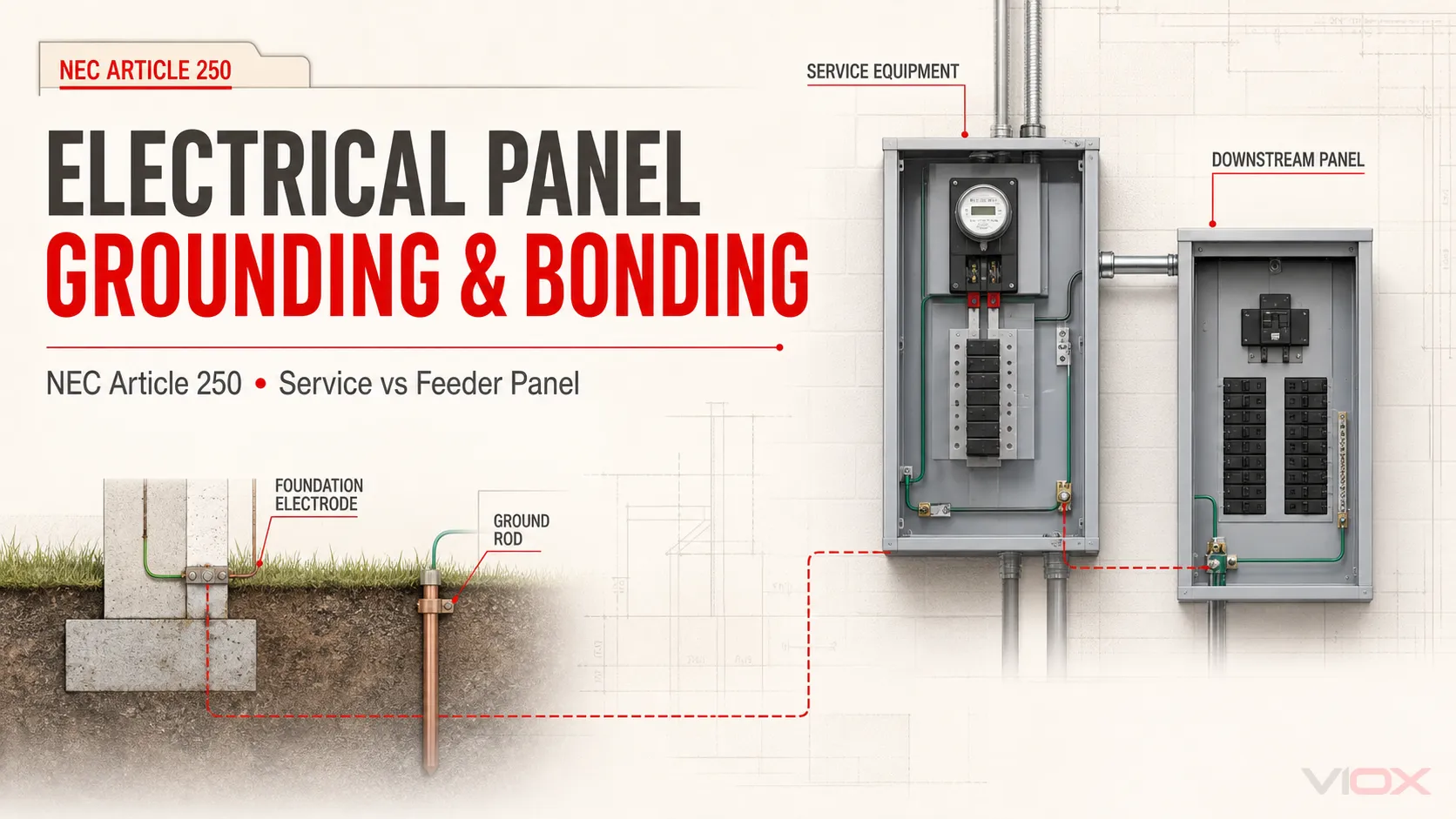
Grounding an electrical panel is not simply attaching the panel to a ground rod. For a typical service-supplied system, the design must provide both a grounding electrode system and an effective ground-fault current path. At the service equipment, the grounded conductor is connected to the equipment-bonding network at the permitted service bonding point. In downstream feeder panels, the grounded conductor is normally isolated from the enclosure and equipment grounding conductors.
The label on the door—“main panel” or “subpanel”—does not settle the issue. First identify the service disconnecting means, the source, and whether the panel is service equipment, feeder-supplied equipment, or part of a separately derived system. Then apply the locally adopted edition of NFPA 70, the National Electrical Code (NEC), the equipment listing and instructions, utility requirements, and the authority having jurisdiction (AHJ).
Safety boundary: Panel work can expose service conductors and line terminals that remain energized even when the main breaker is open. This article is a conceptual NEC guide, not an installation or energized-testing procedure. Design, alteration, verification, and servicing should be performed by qualified persons using the exact equipment documentation and required electrical safe-work practices.
The Three Paths That Must Not Be Confused
Most grounding errors begin by treating three different current paths as one.
| Path | Normal role | What it must not be confused with |
|---|---|---|
| Grounded conductor, commonly neutral | Carries normal return current for connected line-to-neutral loads | Equipment grounding conductor or grounding electrode conductor |
| Effective ground-fault current path | Carries fault current through bonded metal and the equipment grounding path back toward the source so the protective device can operate | A current path that depends primarily on soil or a ground rod |
| Grounding electrode connection | Connects the system to qualifying electrodes at the building or structure | A substitute for an equipment grounding conductor or overcurrent protection |
OSHA describes the equipment grounding conductor as the path that returns dangerous fault current toward the supply source and enables circuit breakers or fuses to operate. Its electrical standard also requires the grounding path from circuits, equipment, and enclosures to be permanent, continuous, and effective. The NEC applies the same essential system logic: earth is not used as the normal effective ground-fault current path.
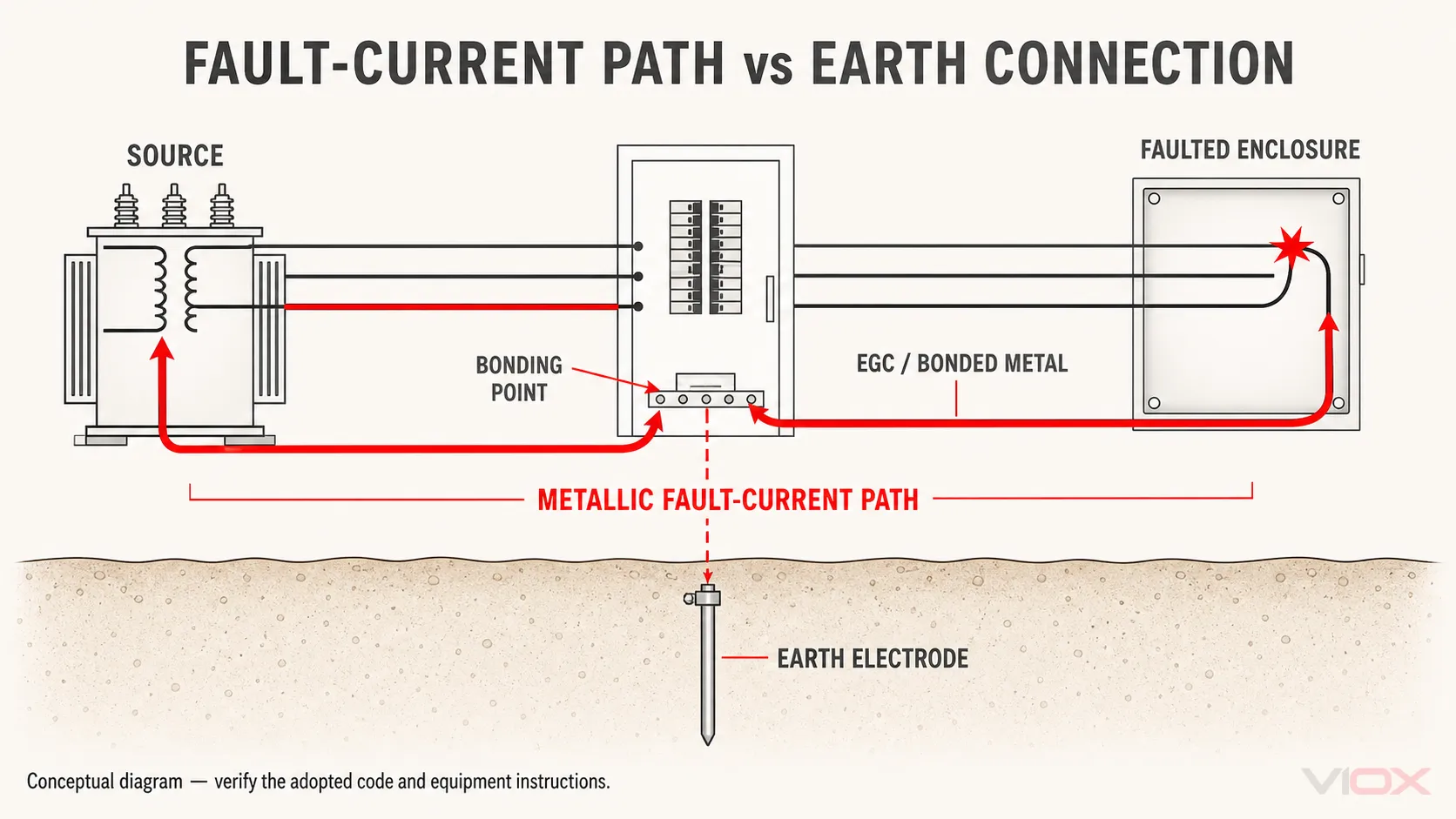
Consider a line conductor that contacts a bonded metal enclosure. The intended clearing path is through the enclosure bonding and equipment grounding path, through the service bonding connection, and back to the source winding. That low-impedance metallic circuit permits enough fault current to flow for the applicable overcurrent protective device to operate within its characteristics.
The grounding electrode system performs other necessary functions, including connecting the premises system to earth and helping limit voltage relative to ground under specified conditions. It does not make a missing equipment grounding path acceptable, and adding another ground rod does not repair a broken feeder equipment grounding conductor.
Service Equipment vs Downstream Panel Grounding
The first design question is not “Where is the green screw?” It is “What electrical boundary does this enclosure occupy?”
| Panel context | Grounded conductor / neutral | Equipment grounding and enclosure | Grounding electrode connection |
|---|---|---|---|
| Service equipment at the service disconnecting means | Connected to the equipment-bonding network through the required or permitted main bonding arrangement | Enclosure and equipment grounding termination are bonded into the effective fault-current path | Grounding electrode conductor connects the service grounding/bonding point to the grounding electrode system as permitted by the adopted code |
| Downstream feeder panel | Normally isolated from the enclosure and equipment grounding bar | Equipment grounding bar and enclosure are bonded to the feeder equipment grounding path | A local electrode, where required for a separate building or other condition, does not replace the feeder equipment grounding path or authorize a second neutral bond |
| Separately derived system | Bond location depends on the system source, disconnect arrangement, protection, and the applicable NEC provisions | Requires a system-specific bonding and grounding analysis | Uses the applicable grounding electrode connection for that derived system |
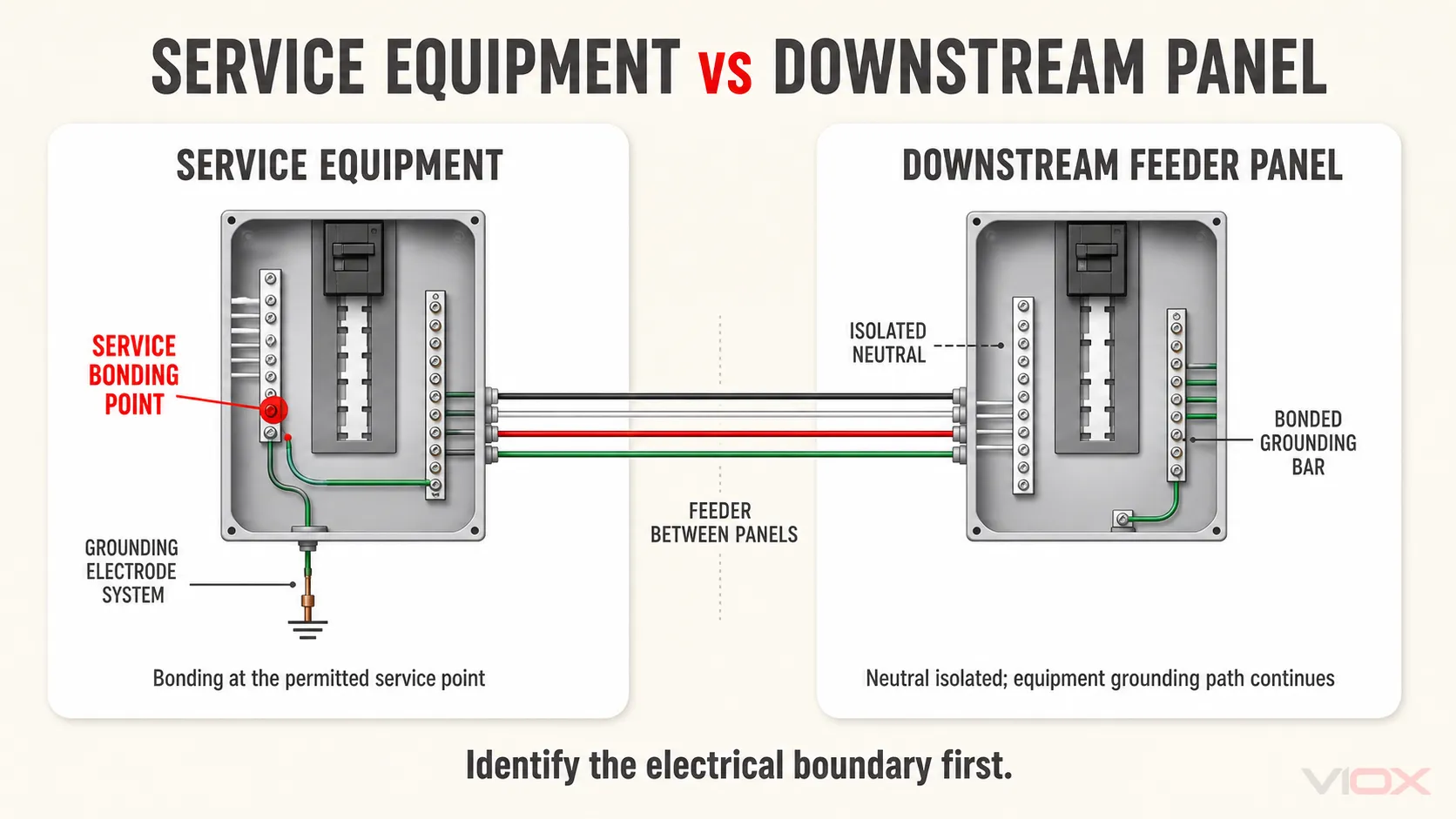
Why the downstream neutral is normally isolated
If the grounded conductor is reconnected to the enclosure or equipment grounding system on the load side of the service bonding point, normal neutral current can divide across metal raceways, equipment grounding conductors, enclosures, and other bonded paths. That makes normally non-current-carrying metal part of the normal return circuit.
NFPA’s public NEC development material for Section 250.24 states the load-side rule: except where the Code specifically permits otherwise, the grounded conductor is not reconnected to equipment grounding conductors, normally non-current-carrying metal, or ground on the load side of the service disconnecting means. This is why the service boundary—not the everyday nickname “main panel”—controls the decision.
For a closer look at bus construction, use the separate neutral bar vs grounding bar guide. An isolated neutral bar and a bonded equipment grounding bar are functional requirements in a downstream panel, not merely visual preferences.
NEC Article 250 Crosswalk for Panel Review
Article 250 covers a broad grounding and bonding system. The following crosswalk identifies the parts most relevant to a panel review without reproducing the Code or replacing the adopted edition.
| Article 250 area | Review question | Evidence to collect |
|---|---|---|
| General grounding and bonding performance | Is there an effective, permanent, continuous fault-current path, and are objectionable current paths avoided? | One-line diagram, feeder method, bonding continuity, field condition |
| Service-supplied systems | Where is the service disconnecting means, and where is the service bonding connection permitted? | Service equipment markings, utility/service layout, panel and disconnect instructions |
| Main bonding jumper | Is the bonding means present, correctly located, listed or provided for the equipment, and appropriately sized? | Equipment label/manual, conductor and service data, adopted NEC tables |
| Grounding electrode system | Which qualifying electrodes are present, and are those present bonded together as required? | Foundation and site records, electrode inspection, connection documentation |
| Grounding electrode conductor | Is its material, routing, protection, connection, and size correct for the actual service and electrodes? | Service conductor data, adopted NEC requirements, listed connector information |
| Equipment grounding conductor | Does the feeder and each circuit provide an approved fault-current path? | Wiring method, conductor/raceway continuity, upstream/downstream drawings |
| Bonding of enclosures and metal systems | Are all required conductive parts electrically continuous without creating normal-current paths? | Enclosure, raceway, water-pipe, structural-metal, and bonding inspection |
Section numbers and table details can change between editions, and local amendments may change application. Use the edition adopted by the jurisdiction rather than assuming the newest published NEC automatically governs the project.
The Grounding Electrode System Is More Than a Ground Rod
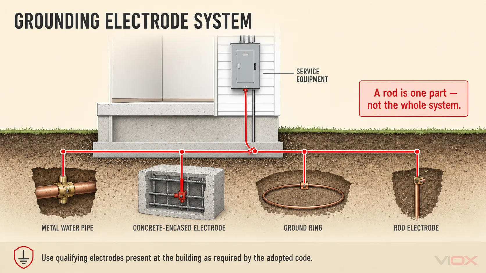
NEC terminology refers to a grounding electrode system, not merely “the rod.” NFPA’s public material for Section 250.50 states that qualifying grounding electrodes present at a building or structure are bonded together to form that system.
Depending on the site and the adopted Code, the system may include qualifying metal underground water pipe, in-ground metal support, a concrete-encased electrode, a ground ring, listed electrodes, rod or pipe electrodes, or plate electrodes. Presence does not automatically prove qualification: dimensions, contact with earth, continuity, accessibility, corrosion protection, and connection methods all matter.
Can reinforcing steel be used?
The blanket statement “the NEC forbids rebar as an electrode” is incorrect. A qualifying concrete-encased electrode can use steel reinforcing bar or rod that meets the applicable construction, length, diameter, continuity, concrete-encasement, and earth-contact conditions. Ordinary reinforcing steel does not qualify automatically, and an inaccessible electrode in an existing building has specific treatment. Verify the actual foundation and the adopted NEC edition.
What does the 25-ohm rule mean?
The often-cited 25-ohm provision is limited to the applicable single rod, pipe, or plate electrode rule. Under the common NEC arrangement, if one such electrode is not demonstrated to have resistance to earth of 25 ohms or less, a supplemental electrode is installed and spaced as required. This is not a universal target for every type of grounding electrode or a promise that adding rods will create an effective equipment fault-current path.
OSHA’s construction grounding guidance similarly states that a single electrode above 25 ohms is augmented by an additional electrode at least 6 feet away. The project must still follow the adopted NEC text, local amendments, testing method, electrode type, and AHJ interpretation. Do not convert this limited provision into a universal “panel must test below 25 ohms” rule.
What Each Conductor and Jumper Does
| Item | Connects | Primary function | Selection authority |
|---|---|---|---|
| Grounded conductor | Source neutral point to permitted loads and the service grounding/bonding point | Normal return path and grounded system reference | System design, adopted NEC, equipment instructions |
| Equipment grounding conductor (EGC) | Equipment enclosures and grounding terminals back toward the source bonding point | Part of the effective ground-fault current path | Wiring method, circuit/feeder design, adopted NEC |
| Grounding electrode conductor (GEC) | Service or derived-system grounding point to the grounding electrode system | Connects the electrical system to the electrode system | Service/derived-system data, electrode type, adopted NEC |
| Main bonding jumper (MBJ) | Grounded conductor to the equipment-bonding network at service equipment | Completes the service fault-current return relationship | Service equipment construction and adopted NEC |
| System bonding jumper (SBJ) | Grounded conductor to the equipment-bonding network for a separately derived system | Establishes the derived-system bonding point | Source and disconnect architecture, adopted NEC |
These names describe electrical functions, not interchangeable pieces of green or bare wire. Sizing a GEC from an EGC table, using a grounding bar as a neutral bar, or assuming every bonding screw belongs in every enclosure can produce an incorrect installation.
Qualified-Person Inspection Checklist
This checklist is for scoping and documenting a professional review. It deliberately avoids terminal-by-terminal instructions.
- Identify the source and boundary. Locate the service point, service disconnecting means, feeder origins, alternate sources, and separately derived sources.
- Identify every conductor function. Distinguish ungrounded conductors, grounded conductor, equipment grounding conductor, grounding electrode conductor, and bonding jumpers from drawings and equipment markings.
- Locate each neutral-to-ground connection. Confirm that service and derived-system bonding points match the approved design and that no unintended downstream connection creates parallel normal-current paths.
- Verify downstream neutral isolation. Check the neutral bar, enclosure, equipment grounding bar, feeder wiring method, and any bonding screw or strap against the listed panel instructions.
- Map the complete fault-current path. Confirm continuity from exposed conductive parts back toward the source bonding point. Do not credit soil or an isolated rod as the normal clearing path.
- Inventory the grounding electrodes. Determine which qualifying electrodes are present and whether required electrodes are bonded into one system.
- Check conductor and connector evidence. Verify material, size, routing, physical protection, connector listing, environmental suitability, and termination permissions from the adopted NEC and exact equipment instructions.
- Check terminal use and torque documentation. Confirm conductor count, conductor material/range, preparation, and torque from the equipment marking or manufacturer instructions; do not use a generic torque value.
- Plan de-energization and verification. A qualified person must address service-side energized parts, lockout/tagout, test-instrument suitability, and required personal protective equipment under the applicable electrical safe-work rules.
- Record the adopted code and approval basis. Note the NEC edition, local amendments, permit/AHJ requirements, equipment documentation, test results, and corrective actions.
Common Findings and What They Actually Mean
| Finding | Why it matters | What does not fix it by itself |
|---|---|---|
| Neutral bonded again in a downstream panel | Can place normal neutral current on equipment grounding and bonded metal paths | Adding a ground rod |
| Missing or discontinuous feeder equipment grounding path | May prevent the intended metallic fault-current path from carrying sufficient current for protective-device operation | A local earth electrode alone |
| Grounding electrode conductor present but disconnected or corroded | Compromises the connection between the electrical system and grounding electrode system | Assuming the branch-circuit EGC performs every electrode function |
| Only one electrode considered while other qualifying electrodes are present | May leave the required grounding electrode system incomplete | Treating the easiest visible rod as the whole system |
| Bonding screw status inferred from panel nickname | Can put the bond on the wrong side of the service disconnect | Calling one enclosure the “main panel” |
| Multiple conductors under a terminal not identified for that use | Can create unreliable connections and violate equipment instructions | Tightening to a guessed torque |
Grounding and bonding also do not replace ground-fault circuit-interrupter (GFCI) protection or surge protective devices where those functions are required. The grounding vs GFCI vs surge protection guide separates those three safety layers.
Focused Questions
Does opening the main breaker make the whole panel safe?
No. Service conductors and line-side terminals ahead of the disconnect may remain energized. The panel must be assessed under applicable electrical safe-work practices by a qualified person; a non-contact indicator or a generic multimeter check is not a substitute for that process.
Should neutral and ground be bonded in a subpanel?
In a typical feeder-supplied downstream panel, the grounded conductor is isolated from the enclosure and equipment grounding conductors. The exact decision depends on the actual service, feeder, separately derived source, existing-installation conditions, equipment listing, and adopted Code—not the word “subpanel” alone.
Does a detached-building panel need a ground rod?
A building or structure supplied by a feeder can have grounding electrode requirements in addition to its feeder equipment grounding path. A local electrode does not replace the equipment grounding conductor or authorize an unintended neutral-to-ground connection. Verify the feeder, building, and existing-installation rules in the adopted edition.
Can a ground rod trip a circuit breaker during a ground fault?
The normal design does not rely on earth as the effective ground-fault current path. The bonded metallic equipment grounding path back toward the source is what enables sufficient fault current to operate the overcurrent protective device within its characteristics.
Who should review panel grounding?
Use a qualified electrical professional familiar with the locally adopted NEC edition, service equipment, the exact panel listing and instructions, and the AHJ’s requirements. A technical article can explain the decision boundaries; it cannot verify the condition of a specific installation.