On this page
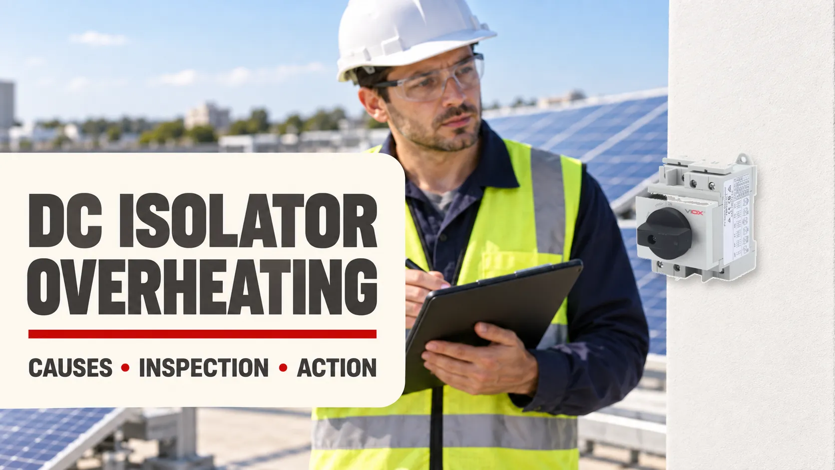
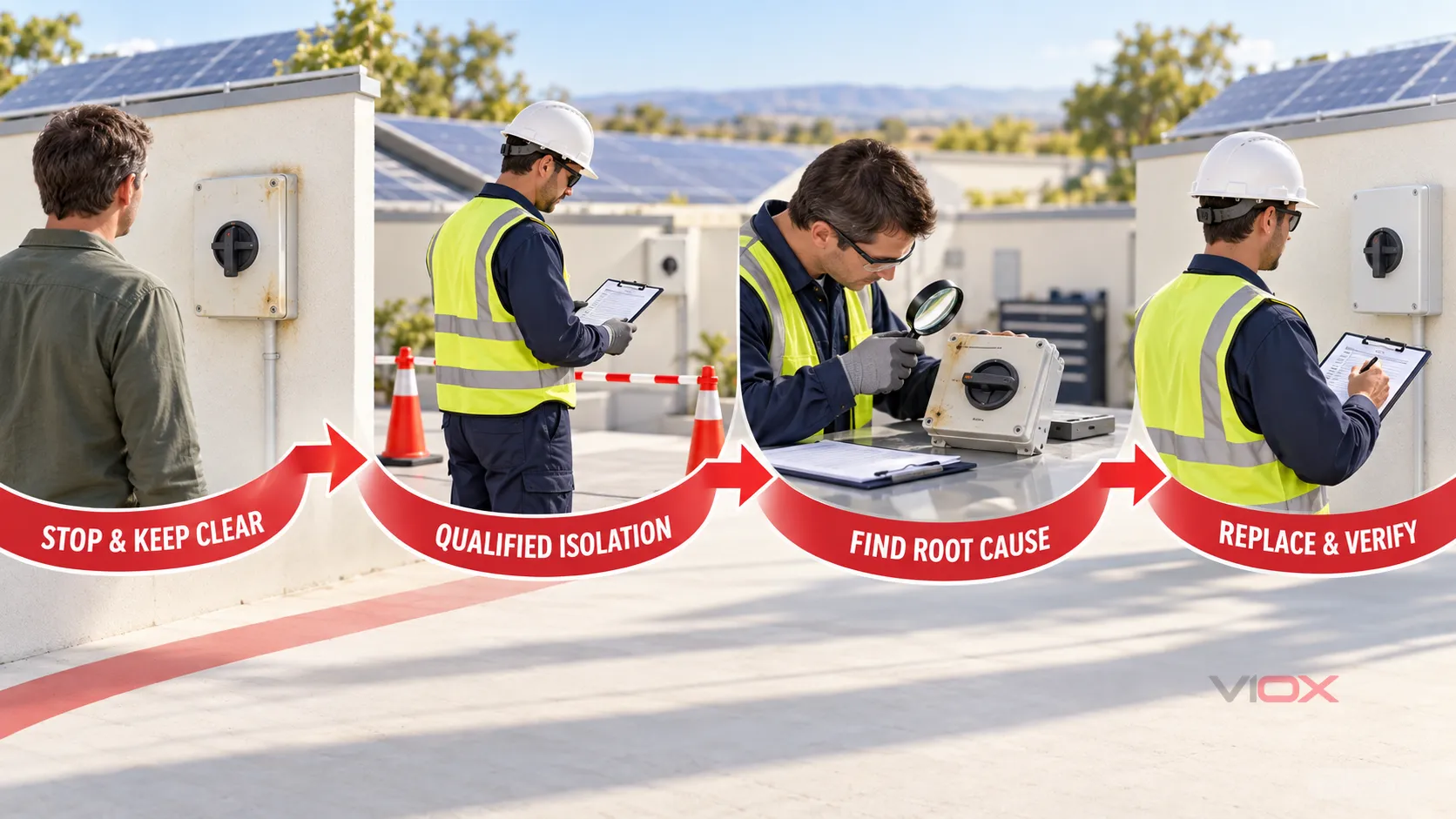
A solar DC isolator that is unusually hot, discolored, deformed, crackling, smoking, burnt, or melted should be treated as failed electrical equipment. Do not open it, retighten it, or keep operating it to see whether the symptom returns. Keep people away, follow the documented site or system emergency procedure, and arrange assessment by a qualified PV electrician. If there is smoke, flame, or an immediate fire risk, move to a safe location and contact emergency services.
The main cause families to investigate are high-resistance terminations, water ingress and corrosion, an unsuitable voltage/current/duty or connection arrangement, damaged switching contacts or mechanism, and heat from an adjacent cable or connector fault. The visible damage shows where heat appeared; it does not, by itself, prove where the failure began.
Key Takeaways
- A burnt or melted DC isolator is a replace-and-investigate condition, not a routine retightening job.
- PV array conductors can remain energized whenever light reaches the modules. Turning a handle to OFF does not make every conductor inside the enclosure safe.
- Localized terminal heating usually points first to a high-resistance joint, conductor-preparation problem, incompatible termination, or corrosion—but the exact root cause must be verified.
- Water can corrode terminals and contacts, reduce effective current-carrying area, and raise resistance. An IP rating does not compensate for an incorrectly installed gland, damaged seal, unsuitable entry, or condensation problem.
- Arcing during operation can indicate damaged contacts, an incomplete switching action, incorrect connection topology, or a switch not suitable for the actual PV DC duty.
- A DC isolator is a manual switching and isolation device. If it “does not work,” do not expect it to trip like a circuit breaker; diagnose whether it will not operate, will not stay in position, fails to interrupt, has abnormal resistance, or has mechanically failed.
For the device’s normal purpose and operating boundary, see what a DC isolator switch is.
DC Isolator Failure Diagnosis Table
Use this table to organize observations, not to authorize live work. “Qualified inspection” means work performed under the applicable safe-isolation procedure, with the exact product instructions and local electrical rules available.
| Symptom | Possible causes | Safe evidence to collect | Qualified-person checks | Recommended action |
|---|---|---|---|---|
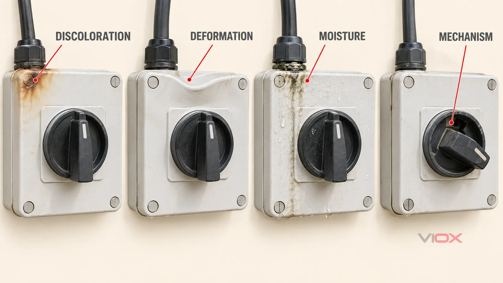
| Blackened terminal area or localized discoloration | Loose or damaged termination; incomplete conductor insertion; wrong lug, ferrule, conductor class, or terminal; corrosion | Exterior photograph, location, time, load condition, odor or sound—without opening or touching the enclosure | Establish a safe work condition; examine conductor preparation, terminal and adjacent insulation; compare recorded installation torque and components with the exact instructions | Replace heat-damaged parts and remake the termination with compatible components; do not merely retighten a carbonized or softened assembly |
| Enclosure warped, blistered, or melted | Sustained localized resistance heating; overloaded or incorrectly derated device; hot adjacent joint; contact damage | Photograph the deformation and nearby cable/connector condition from a safe distance | Determine the heat origin; verify operating current, ambient/enclosure conditions, DC ratings, duty, conductor condition, and nearby connections | Remove the affected equipment from service; replace damaged equipment and correct the initiating cause before recommissioning |
| Crackling, flash, or arcing during operation | Worn or contaminated contacts; incomplete switching action; wrong pole arrangement; voltage/current/duty beyond the declared capability; model-specific defect | Do not repeat the operation; record the handle position and event circumstances from a safe location | Follow the model and any recall instructions; verify connection diagram, pole use, DC duty/utilization category, PV maximum voltage/current, and mechanism condition | Stop use and replace the device if damaged or suspect; correct selection or topology errors before energization |
| Water droplets, condensation, corrosion, or staining | Failed seal or gland; unsuitable cable entry; damaged enclosure; conduit drainage problem; thermal cycling and condensation | Exterior evidence of water tracks, cracked housing, loose gland, missing shroud, or conduit route | Inspect entry system, gaskets, mounting points, enclosure integrity, corrosion extent, drainage and the applicable installation requirements | Replace contaminated or corroded equipment; repair the water-entry path and restore the required enclosure protection |
| Handle stiff, loose, broken, will not latch, or position is uncertain | UV/impact damage; mechanical wear; heat deformation; internal contact/mechanism fault | Note the position and visible mechanical condition; do not force the handle | Compare the mechanism behavior with the exact instructions; verify contact state only under a controlled safe-work method | Replace the isolator; do not modify, lubricate, drill, or force the operating mechanism unless the manufacturer explicitly provides a procedure |
| Solar generation lost but no obvious exterior damage | Open contact; failed termination; cable or connector fault; inverter or system fault unrelated to the isolator | Record inverter messages, time, weather and whether the loss is intermittent—without opening DC equipment | Systematic testing to separate array, cable, connector, isolator and inverter causes | Repair the confirmed cause; do not replace the isolator solely because generation stopped |
| Isolator looks normal but is much hotter than comparable equipment | Early high-resistance joint; uneven loading; contact deterioration; external solar heating; measurement error | No-touch observation only; preserve operating and weather conditions | Qualified thermography or temperature measurement using a safe method; compare equivalent points under similar load and account for emissivity and solar gain | Investigate the abnormal delta; use the product’s declared limits and evidence, not a universal internet temperature threshold |
Why a Small Resistance Increase Can Become a Burnt DC Isolator
Current passing through resistance produces heat. At a connection, the basic relationship is:
P = I²R
This does not mean a field technician can calculate the condition of a terminal from one temperature reading. It explains why a small, localized rise in resistance can matter when current flows for hours.
A common escalation path is:
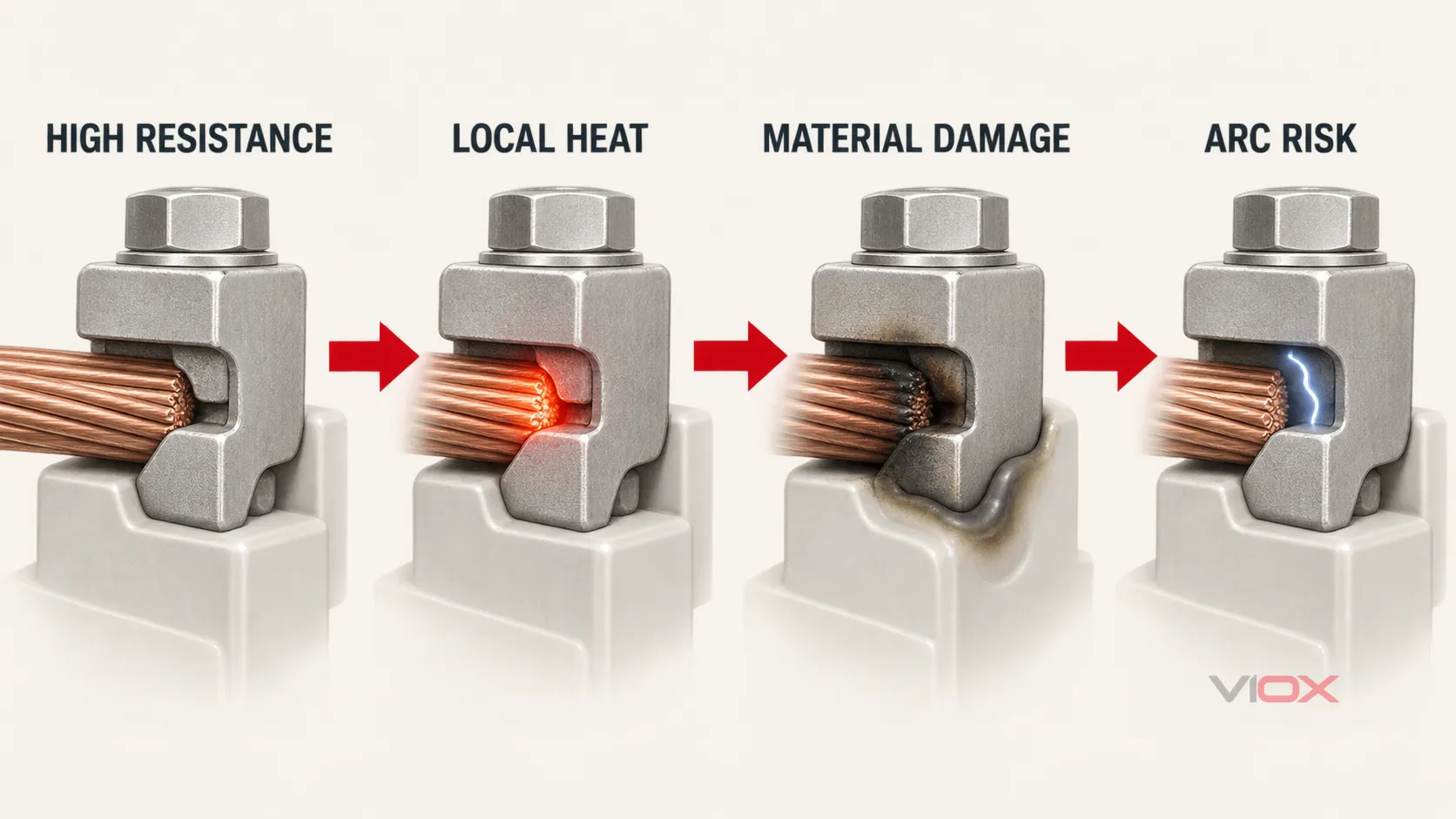
- A loose, contaminated, corroded, damaged, or poorly matched contact reduces the effective contact area.
- Local resistance rises and creates concentrated heating.
- Heating accelerates oxidation, softens nearby polymer, relaxes contact pressure, or further damages the contact surface.
- Resistance and temperature rise again, creating a reinforcing failure cycle.
- The circuit may fail open, contacts may weld, insulation may carbonize, or an arc may form. In the worst case, nearby combustible material can ignite.
Energy Safe Victoria has identified water damage and loose low-voltage cable connections within DC isolator enclosures as leading causes in unsafe audited PV systems. Its published analysis also describes how corrosion can reduce the contact area, increase resistance, melt a contact, and in some circumstances contribute to fire. That evidence supports the failure chain; it does not prove that every burnt isolator has the same root cause.
Six Root-Cause Families to Check
1. High-Resistance Cable Terminations
Terminal heating is often an interface problem rather than a simple “too much current” problem. Possible contributors include insufficient or excessive tightening, damaged strands, incomplete conductor insertion, insulation caught in the clamping area, an unsuitable ferrule or lug, a conductor type outside the terminal’s declared range, or strain transferred from the cable into the terminal.
The correct torque is the value in the exact product instructions for the applicable terminal and conductor—not a generic value copied from another switch. Torque evidence is also not a cure after overheating: once a terminal, conductor, contact carrier, or enclosure has discolored, softened, pitted, or carbonized, retightening may hide the symptom while leaving damaged material in service.
Energy Safe Victoria’s installer guidance specifically tells installers to tighten terminals, including bridging-link terminals, to manufacturer requirements and to ensure multistranded conductors are correctly retained. The VIOX DC isolator connection guide can help explain normal topology, but the exact model diagram remains controlling.
2. Water Ingress, Condensation, and Corrosion
Water can enter through a poorly selected or installed gland, an unauthorized enclosure penetration, a damaged gasket, a cracked housing, an unsuitable cable or conduit route, or pressure and condensation cycles. Corrosion at a terminal or switch contact can increase resistance even when the outside of the enclosure initially looks intact.
Energy Safe Victoria’s PV DC isolator guidance emphasizes maintaining the declared IP protection, using manufacturer entry and mounting points, avoiding top-face cable entry, providing suitable glands and conductor strain relief, and addressing drainage or condensation where required. These are Australian requirements and guidance; installers in other markets must apply their own code and manufacturer instructions.
For a deeper treatment of UV exposure, enclosure materials, cable entry, and outdoor damage, read why outdoor isolators fail.
3. Voltage, Current, Duty, or Derating Mismatch
A switch can carry a familiar ampere marking yet still be unsuitable for the actual PV circuit. Selection must consider the maximum DC voltage under the system’s design conditions, current from each string and any parallel paths, the declared pole arrangement, load-breaking duty or utilization category, enclosure and ambient conditions, and applicable derating.
DC arcs do not pass through a natural current zero every half-cycle as AC arcs do. The switch and connection arrangement must therefore be designed and declared for the relevant DC duty. A device selected from an AC rating, a different pole configuration, or an unrelated utilization category may not provide the expected interruption performance.
Use the DC isolator rating guide to identify the documents and markings that need to be checked. Do not infer a product’s breaking capability from its current rating alone.
4. Incorrect Pole Arrangement or Connection Topology
Some PV DC isolators use multiple contacts in a manufacturer-defined series or circuit arrangement to achieve their declared DC performance. A visually plausible alternative connection can be electrically wrong. Incorrect pole use may concentrate stress on fewer contacts, defeat the intended arc-control path, or leave an unexpected live path.
There is no safe universal color-by-terminal or “all four-pole isolators wire the same way” rule. Verify the exact model’s diagram, polarity requirements if stated, bridge arrangement, current direction limitations if stated, and the installation design. A conceptual internet diagram is not construction authority.
5. Contact or Operating-Mechanism Damage
Pitted, contaminated, welded, misaligned, or incompletely closed contacts can heat or arc. A slow, damaged, obstructed, or partially operated mechanism can also leave the switch in an unsafe state. Product recalls demonstrate that certain model-specific internal faults have caused overheating, arcing, or fire; those notices apply to named products and must not be generalized to every DC isolator.
If a model is subject to a recall or authority warning, follow that notice exactly. Some official recall notices specifically tell owners not to operate the DC isolator and instead to use the stated system shutdown procedure. Never repeatedly turn a suspect handle to “test” whether it still works.
6. Heat Originating Outside the Isolator
A melted enclosure does not automatically make the isolator the initiating fault. A nearby mismatched PV connector, damaged cable, loose external joint, inverter terminal, or combiner-box connection can generate heat or arcing that spreads to the switch.
Inspection should follow the heat pattern and electrical path beyond the visibly damaged enclosure. Replacing only the isolator while leaving the initiating cable, connector, support, sealing, or design defect in place invites recurrence.
What an Owner Can Observe—and What Requires a PV Electrician
An owner or site operator can record external evidence without touching or opening equipment:
- smoke, odor, unusual sound, discoloration, deformation, water tracks, cracked plastic, or a changed handle position;
- inverter alarms or loss of generation;
- the time, weather, operating condition, and recent maintenance or storm event; and
- clear photographs taken from a safe distance.
Do not remove the cover, touch the enclosure to judge temperature, force the handle, apply water, tighten a gland, or disconnect a PV connector. PV modules produce DC whenever illuminated, and the array side can remain energized even after AC equipment is switched off.
A qualified PV electrician should control the work area, review the system shutdown and emergency information, identify all energy sources, apply the legally required safe-isolation method, and verify the condition of each relevant part before access. The investigation may include visual examination, comparison with model instructions and installation records, appropriate de-energized testing, and thermography under controlled operating conditions when justified. The test method must fit the system and jurisdiction; this article is not a terminal-level test procedure.
How Hot Is Too Hot?
There is no defensible universal surface-temperature number for every solar DC isolator. Acceptable temperature rise depends on the exact product, terminal, current, conductor, enclosure, ambient temperature, installation, duty, and test method. Sunlight can also heat an outdoor enclosure independently of electrical loss, while emissivity can distort infrared readings.
Useful evidence is comparative and contextual: one terminal or pole significantly hotter than equivalent points under similar load, a temperature pattern concentrated at a joint, a trend that worsens over time, or a measured condition outside the product documentation. Visible discoloration, deformation, odor, smoke, crackling, or melting already overrides the need to debate a temperature threshold—stop using the equipment and investigate.
Replace or Repair a Burnt DC Isolator?
Replace the isolator when there is melting, carbonization, contact or terminal damage, internal moisture or corrosion, a cracked enclosure, uncertain switching state, failed mechanism, illegible safety identification, or a relevant recall instruction. The associated conductor, lug or ferrule, gland, bridge, enclosure accessory, and adjacent equipment must also be assessed; replacement scope should follow the damage and root cause.
A field “repair” is limited to work explicitly permitted by the manufacturer using specified parts and procedures. Do not sand contacts, glue a cracked case, drill a drain hole, bypass poles, improvise bridges, transfer a heat-damaged mechanism into another enclosure, or reuse conductors whose strands or insulation have been thermally damaged.
The key decision is not “Can the handle move again?” It is “Can the complete isolation function, current path, enclosure protection, and installation be shown to meet the exact product and system requirements after the initiating fault has been removed?” If that evidence is unavailable, replacement is the conservative choice.
Before Re-Energizing the PV System
The responsible electrical professional should document that:
- the initiating cause has been identified or the replacement scope conservatively covers every plausible damaged element;
- the replacement isolator is suitable for the system’s maximum DC voltage, current, pole arrangement, switching duty, enclosure, ambient conditions, and applicable rules;
- conductor type, preparation, insertion, ferrules or lugs, bridging links, and terminal torque follow the exact instructions;
- cable support and strain relief prevent force on terminals;
- glands, entry direction, seals, mounting points, drainage, shrouds, and condensation controls preserve the required environmental protection;
- polarity and the manufacturer’s connection arrangement have been verified;
- adjacent cables, connectors, combiner equipment, and inverter interfaces have been checked for related damage;
- required inspection and tests have been completed with recorded results; and
- labels, shutdown information, documentation, and any local inspection requirements are current.
Preventive maintenance should use the interval required by the manufacturer, local rules, site risk, and environmental exposure. Do not adopt a universal retorque schedule: disturbing a sound connection can create a new defect, while a heat-damaged joint needs assessment rather than periodic tightening.
Selecting a Replacement DC Isolator
Replacement starts with the circuit and environment, not with matching only the old device’s ampere number. Confirm the PV voltage envelope, current paths, pole and wiring arrangement, declared DC switching duty, enclosure and mounting method, cable-entry system, conductor compatibility, and the evidence required in the target market.
IEC 60947-3 covers switches, disconnectors, switch-disconnectors, fuse-combination units, and dedicated accessories within its stated low-voltage scope, including equipment up to 1,500 V DC. That scope does not prove that any particular model is certified or suitable for a specific PV installation. Request the exact datasheet, connection diagram, instructions, declarations, and certificates for the model being evaluated.
VIOX publishes multiple photovoltaic DC isolator switch series for comparison by voltage, current, poles, enclosure, and mounting format. Use the page to shortlist a mechanical format, then request the current model-specific documents before approving a replacement.
Sources
- Energy Safe Victoria — PV d.c. isolators and systems
- Energy Safe Victoria — Regulatory impact statement consultation on rooftop solar PV DC isolators
- Queensland WorkSafe — Inspection and maintenance checklist for solar energy systems
- Queensland WorkSafe — DC solar isolator switch recalls and safety information
- ACCC Product Safety — Avanco DC solar isolator recall
- IEC — IEC 60947-3:2020+AMD1:2025 consolidated scope