On this page
L1, L2, and L3 normally identify the line-side main terminals of a contactor. T1, T2, and T3 identify the corresponding load-side main terminals. When the coil is energized, the main poles close so that L1 connects to T1, L2 to T2, and L3 to T3. On a two-pole contactor, only the first two pairs may be present.
These markings are not the coil connections. A1 and A2 are the coil terminals, while 13-14 commonly identifies a normally open auxiliary contact. Terminal position and permitted line/load orientation can vary, so the markings and wiring diagram for the exact model take priority over a generic photograph.
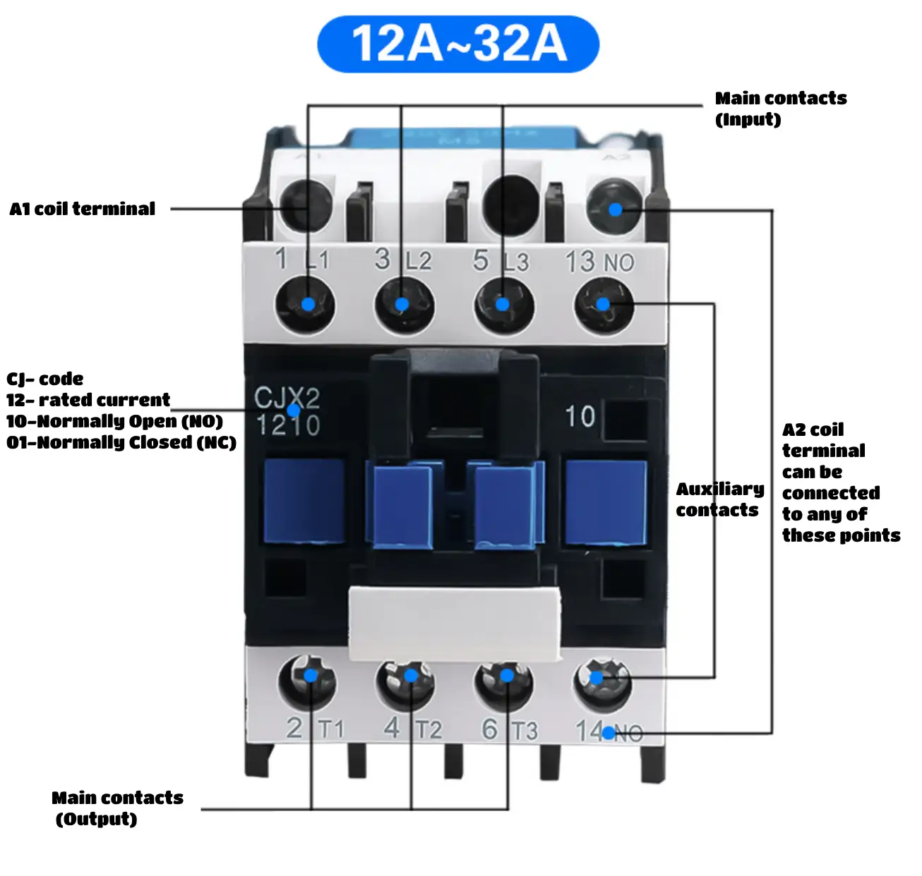
L1, L2, L3 and T1, T2, T3
The L and T labels identify opposite ends of the contactor’s switched main poles:
| Main pole | Line-side terminal | Corresponding load-side terminal | State when the coil is energized |
|---|---|---|---|
| Pole 1 | 1/L1 | 2/T1 | L1 connects to T1 |
| Pole 2 | 3/L2 | 4/T2 | L2 connects to T2 |
| Pole 3 | 5/L3 | 6/T3 | L3 connects to T3 |
On many IEC-style three-pole contactors, the L terminals are physically above the T terminals. That layout is common, but it is not a substitute for reading the molded terminal markings.
L2 also does not automatically mean neutral. In a three-phase circuit, L1, L2, and L3 are the three phase conductors. In some single-phase applications, a second pole may switch another line conductor or the neutral where the circuit design, applicable rules, and device instructions permit it.
For a broader explanation of the switching mechanism, see What Is a Contactor?.
A1 and A2 Are Coil Terminals
A1 and A2 connect the control voltage to the contactor coil. Energizing the correctly rated coil creates the magnetic force that closes the main contacts and changes the state of mechanically linked auxiliary contacts.
Before applying control voltage, check the coil nameplate for:
- rated voltage;
- AC or DC supply;
- frequency for an AC coil; and
- polarity where the manufacturer marks polarity for a DC or electronically controlled coil.
Do not identify A2 only by its physical position. Some product families provide different terminal arrangements or more than one access point to the same coil connection. Follow the exact terminal markings and circuit diagram.
13-14 Is Usually a Normally Open Auxiliary Contact
Under common IEC terminal identification, 13-14 denotes a normally open auxiliary contact. It is separate from the A1-A2 coil circuit and from the L-T main power poles. It may be used for indication, interlocking, or a holding circuit, provided its published utilization category and electrical rating suit the control load.
Other auxiliary-contact numbers can appear on different models. For example, 21-22 commonly identifies a normally closed auxiliary contact. The dedicated auxiliary contact vs main contact guide explains the functional difference.
What Happens When the Coil Is Energized?
With a normally open main-contact contactor, applying the correct voltage across A1-A2 pulls in the armature. The main poles close together, connecting L1-T1, L2-T2, and L3-T3. Removing coil voltage allows the contactor to return to its normal state unless the product uses a different operating mechanism.
This is why the control circuit and power circuit must be treated separately: the coil commands the device, while the main poles carry the switched load current. For a complete connection sequence, use the separate contactor wiring guide rather than inferring a circuit from terminal names alone.
Can the L and T Sides Be Reversed?
Do not assume that every contactor permits reverse line/load connection. Although some conventional AC contactors may have electrically symmetrical main contacts, a manufacturer can specify orientation because of the product’s arc-control design, accessories, monitoring functions, terminal guards, coordination data, or certification conditions.
The safe rule is simple: connect the supply and load as shown in the exact product instructions. If the documentation permits bidirectional connection, follow the stated conditions; otherwise keep the declared line side on L and the load side on T.
Does Swapping L and T Reverse a Three-Phase Motor?
No. Moving all three supply conductors from the L side to the T side does not by itself reverse a three-phase motor, because the phase sequence remains the same.
Motor rotation changes when any two phase conductors are interchanged. A practical forward/reverse starter normally uses two correctly interlocked contactors so both directions cannot be energized at once, together with suitable overload and short-circuit protection. That is a separate circuit-design task—not a consequence of the letters L and T.
What the Terminal Labels Do Not Tell You
The labels identify circuit function, but they do not establish:
- coil voltage or coil type;
- motor power or permissible load current;
- utilization category, such as AC-1 or AC-3;
- short-circuit coordination;
- auxiliary-contact rating;
- conductor size or tightening torque; or
- whether reverse line/load connection is allowed.
Those values must come from the exact nameplate, datasheet, installation instructions, and applicable installation rules. IEC 60947-4-1:2023 covers electromechanical contactors and motor-starters within its stated low-voltage scope, but product compliance does not replace the model-specific connection diagram.
Safe Identification Checklist
- Isolate all power sources, apply the required lockout/tagout procedure, and verify absence of voltage with suitable equipment.
- Read the molded terminal markings rather than relying on top-versus-bottom position.
- Match each main pole: L1-T1, L2-T2, and L3-T3.
- Locate A1-A2 on the device diagram and verify the coil voltage before energizing it.
- Keep 13-14 and other auxiliary contacts separate from the coil and main power circuit.
- Use the manufacturer’s conductor, torque, protection, and orientation requirements for the exact model.
The VIOX AC contactor range provides product-family context; final selection and connection must always be based on the exact model data.