On this page
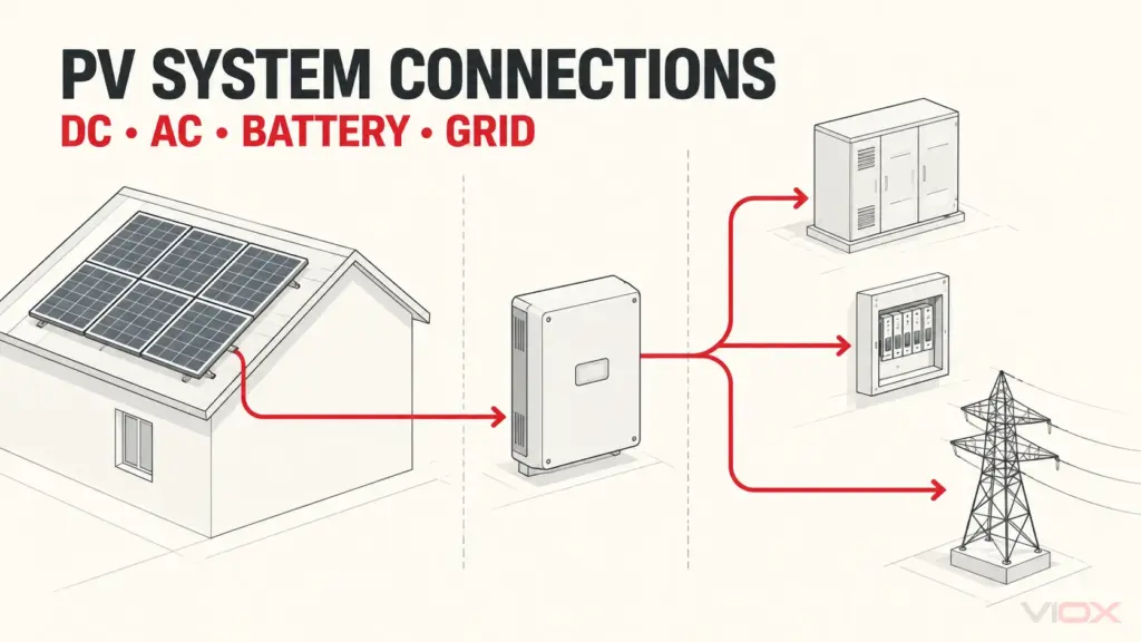
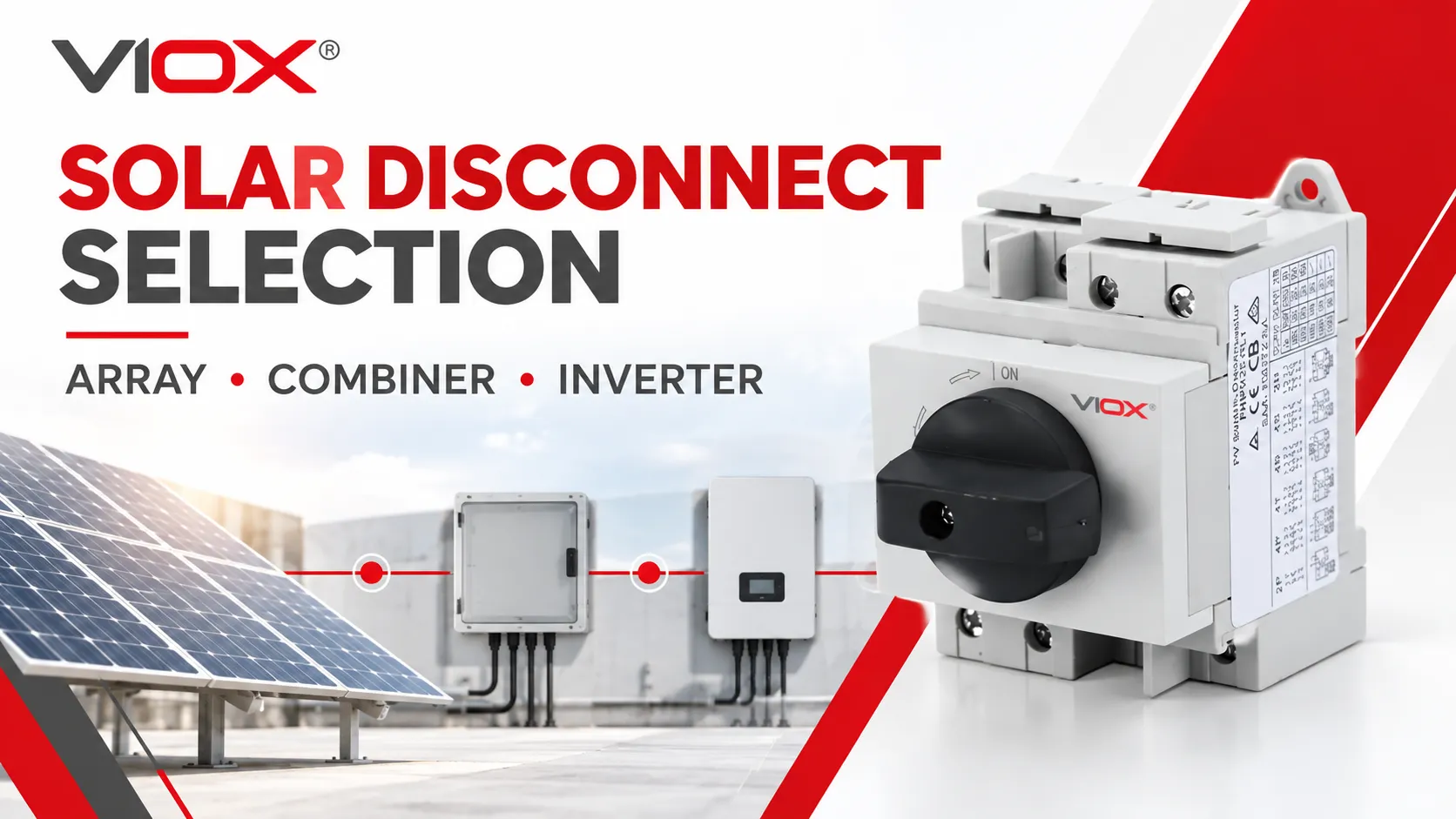
A solar disconnect switch should be selected by the boundary it must isolate—not by choosing a convenient box and then looking for somewhere to install it. In a string-inverter PV system, a DC disconnect may be located near the array, at a combiner output, or within or beside the inverter. Each position isolates a different part of the current path.
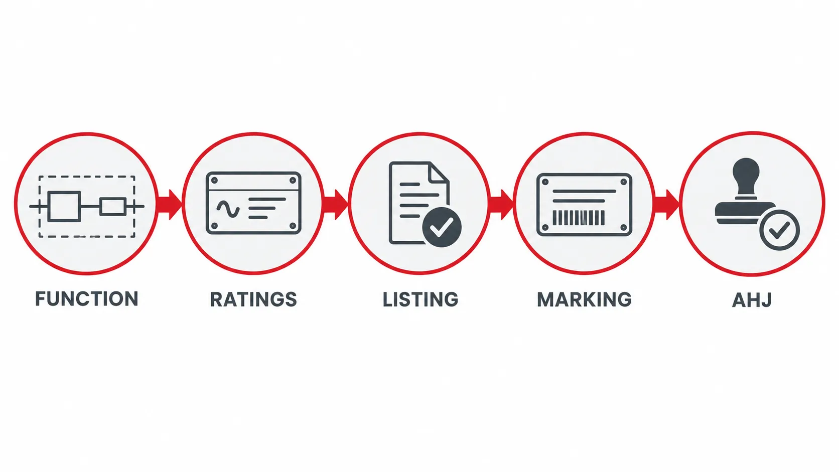
For a U.S. project, location is only the first decision. The final design must also match the locally adopted edition of NFPA 70 (NEC), the equipment listing and markings, manufacturer instructions, available fault current, enclosure conditions, and the authority having jurisdiction (AHJ). An IEC-rated isolator should not be assumed to satisfy a required North American listing, and an inverter handle labeled “DC disconnect” should not be assumed to perform every NEC disconnecting or rapid-shutdown function.
This guide focuses on where the disconnect belongs and what evidence must support it. For the device definition and operating principle, see What Is a DC Isolator Switch?.
The Short Answer: Select the Boundary First
- Choose an array disconnect when the design needs a switching or isolation point close to an array or subarray boundary.
- Choose a combiner-output disconnect when several source circuits are combined and the outgoing feeder must be isolated as one defined section.
- Use an inverter-integrated disconnect when the exact listed inverter assembly and instructions show that the integral device performs the required function for the connected DC inputs.
- Treat rapid shutdown as a separate system function. A disconnect may initiate or participate in rapid shutdown, but opening one mechanical switch does not automatically reduce voltage on every controlled conductor.
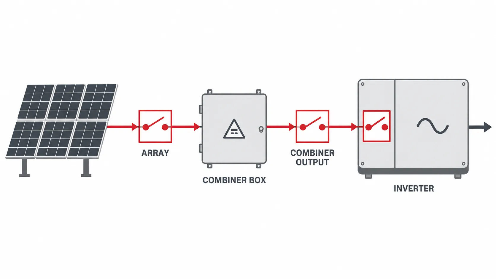
What Each Disconnect Location Actually Isolates
| Candidate location | Boundary created when opened | Strongest use case | Main limitation to check |
|---|---|---|---|
| Array or subarray disconnect | Separates downstream conductors/equipment from the connected array section, subject to actual topology | Field segmentation, maintenance boundary, long DC run, or multiple array zones | Array-side conductors remain energized in light; multiple parallel paths may require more than one device |
| Combiner-output disconnect | Separates the combined output feeder from the downstream inverter or equipment | Centralized architecture with several strings combined into one output circuit | Opening the output does not isolate individual source circuits inside or ahead of the combiner |
| Inverter-integrated DC disconnect | Separates the inverter’s DC conversion section as defined by the listed assembly and instructions | Compact string-inverter installations where the integral function covers the connected inputs | Conductors between array and inverter may remain energized; function depends on listing, markings, and topology |
| External disconnect adjacent to inverter | Creates a visible local isolation point outside the inverter | Service boundary, retrofit, or when the inverter lacks the required integral function | Adds enclosure, conductor, terminal, environmental, and coordination requirements |
The correct answer can be more than one disconnect. A large or segmented array may need field isolation and an inverter service point. Conversely, a smaller listed system may use one integrated device for a defined function. Do not turn the table into a universal placement rule; use it to identify the boundary that the design actually needs.
1. Array Disconnect: Isolating a Field Section
An array disconnect is placed electrically close to an array or subarray output. Its purpose is to create a clear boundary between that source section and the downstream DC run. This can be useful where arrays are separated across roofs or ground-mounted zones, where a long feeder enters another area, or where maintenance plans require field segmentation.
Opening an array disconnect does not make the modules or the conductors between the modules and switch dead. PV modules produce voltage whenever illuminated. With parallel strings, backfeed and multiple source paths must also be considered. The design drawing should therefore state exactly which conductors and equipment are isolated on each side of the device.
Use an array-side switch only when its marked DC voltage, current, switching duty, pole arrangement, conductor range, enclosure, ambient limits, and short-circuit conditions suit that location. Outdoor exposure also brings UV, water entry, condensation, cable support, and operating-access issues. A general IP or NEMA enclosure statement does not override the exact installation instructions.
An array disconnect is a location choice, not automatically a code label. Whether it serves as a PV system disconnecting means, equipment disconnect, maintenance switch, or part of another listed function depends on the adopted code, the design, and the product evidence.
2. Combiner-Output Disconnect: Isolating the Combined Feeder
In a centralized string architecture, a combiner box receives multiple source circuits and sends one combined output toward the inverter. A disconnect on that output creates a practical boundary for the outgoing feeder and downstream equipment.
This location is attractive because one device can interrupt the combined path. It does not, however, isolate the individual source circuits entering the combiner. The line side and internal bus may remain energized from the array. If technicians need to service fuse holders, monitoring components, surge protective devices, or buswork, the maintenance plan must account for the still-energized source side and any additional isolation method provided by the listed assembly.
The output device must be selected for the combined circuit, not for one string. Verify the maximum circuit current under the applicable design rules, maximum DC voltage at the lowest design temperature, available fault or backfeed conditions, required poles, load-switching duty, and the relationship to the combiner’s fuses or other overcurrent protective devices. A fused disconnect and a non-fused disconnect solve different protection architectures; see Fused vs Non-Fused Disconnect Switches for that separate decision.
If the combiner includes a factory-installed switch, use the complete assembly listing, ratings, wiring diagram, and replacement-part instructions. Do not assume that adding a field-installed switch inside a listed enclosure preserves the enclosure or assembly evaluation.
3. Inverter-Integrated Disconnect: Compact, but Scope Matters
Many string inverters include a DC disconnect handle or an associated switch section. This can simplify layout and create a local service point, but the visible handle is not enough evidence to define its scope.
Confirm from the exact inverter documentation:
- which DC input terminals or MPPT channels the device opens;
- whether all ungrounded conductors are switched as required by the system design;
- whether any source-side terminals remain energized in the open position;
- whether the switch is part of the inverter’s listing and which standards apply;
- whether the device is load-break rated for the intended operating condition;
- whether it serves equipment isolation, a PV system disconnecting function, rapid-shutdown initiation, or only a manufacturer-defined service function; and
- what access, lockout, marking, and operating conditions apply.
An integrated disconnect can satisfy a required function only when the listed assembly, markings, instructions, system architecture, adopted NEC edition, and AHJ support that use. An inverter-integrated switch also cannot remove voltage from the array-to-inverter conductors merely by being physically close to the inverter.
DC Disconnect Is Not the Same as Rapid Shutdown
A DC disconnect creates an intentional open point in a circuit. Rapid shutdown is a PV-system function intended to control specified conductors around a building-mounted array after initiation. The detailed conductor boundaries, voltage limits, timing, initiation devices, labeling, and exceptions depend on the adopted NEC edition and the listed rapid-shutdown equipment or system.
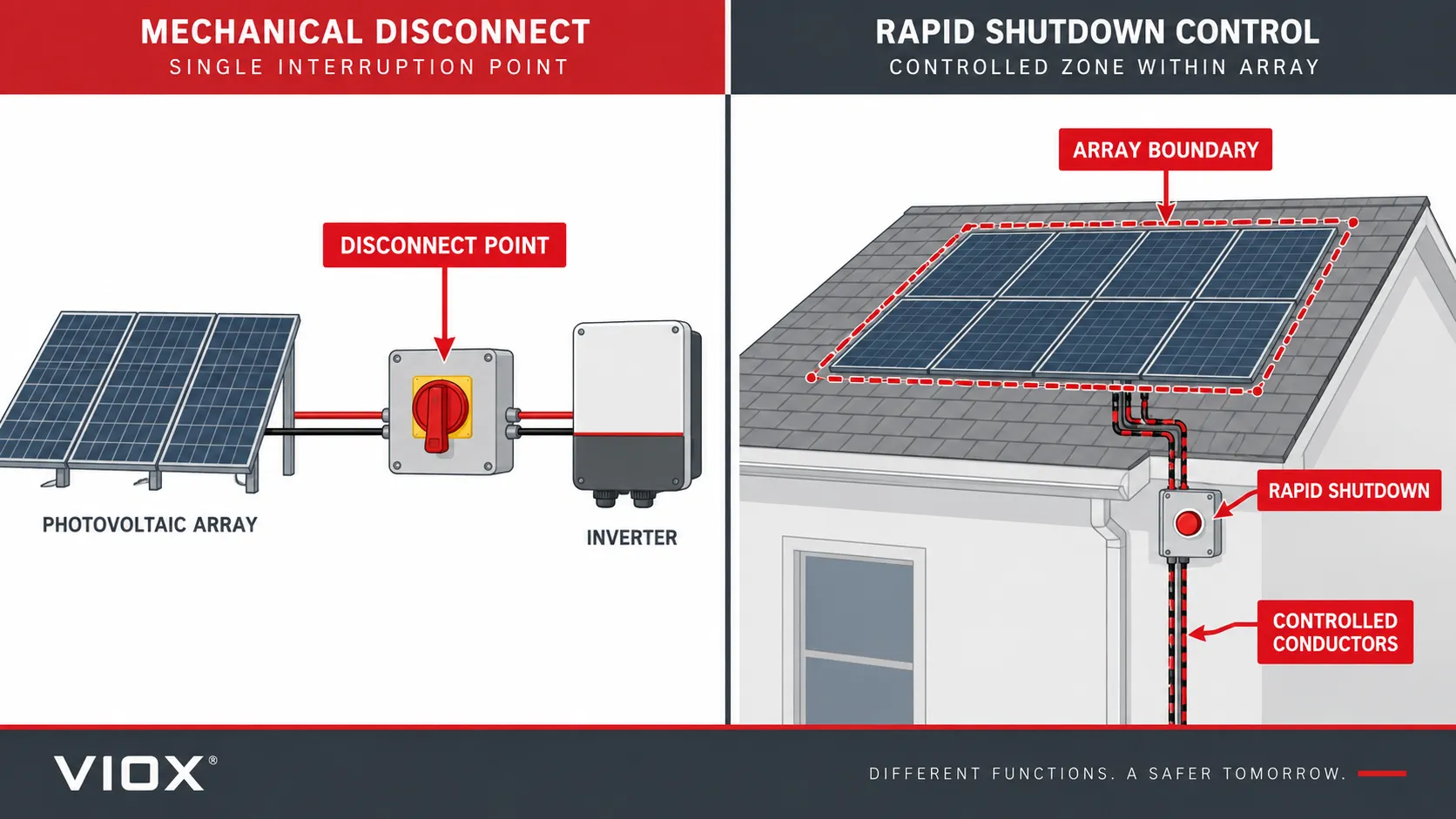
The two functions can interact. For example, a PV system disconnect or another switch may be used as a rapid-shutdown initiation device in a permitted design. That does not make the mechanical disconnect and the rapid-shutdown function identical. Opening one switch may isolate the inverter while conductors closer to the array remain energized; a listed rapid-shutdown system may control conductors without providing the visible physical isolation needed for a maintenance task.
Ask two separate questions:
- What circuit boundary becomes open for maintenance or system disconnection?
- Which conductors are controlled after rapid-shutdown initiation, and to what limits under the adopted code and listing?
If the answers are not shown on the one-line diagram and equipment documentation, the design is not ready for product selection. For a deeper comparison, read Rapid Shutdown vs DC Disconnect.
NEC, UL, and IEC Terms Do Not Map One-to-One
U.S. projects often use the everyday phrase “solar panel disconnect switch.” IEC-oriented catalogs often use “DC isolator” or “switch-disconnector.” Similar hardware may be involved, but approval depends on the function and evidence—not the translated noun.
| Reference | What it primarily governs | Relevant boundary for selection | What it does not prove by itself |
|---|---|---|---|
| NFPA 70 (NEC), especially Article 690 | Installation requirements for PV systems in adopting jurisdictions | Required disconnecting functions, locations, operation, markings, rapid shutdown, and installation relationships | That an unlisted or differently certified product is acceptable for a particular installation |
| UL 98B | Product standard for enclosed, dead-front, and open-type switches for DC PV systems within its scope | PV disconnect switch construction, ratings, tests, and markings under the UL route | Compliance of a model that has no exact certification record or its suitability outside marked conditions |
| UL 508I | Product standard for manual and electromechanical disconnect switches for PV systems within its scope | PV disconnect products associated with industrial-control-switch construction and stated application limits | That every UL 508 switch is a PV disconnect, or that an electromechanical device replaces a required manual means |
| IEC 60947-3 | Product standard for switches, disconnectors, switch-disconnectors, and fuse-combination units within its voltage scope | IEC terminology, switching/isolation functions, utilization categories, and declared ratings | A U.S. listing, NEC installation compliance, or AHJ acceptance |
UL Solutions identifies both UL 98B and UL 508I within its solar balance-of-system certification work. The exact product category and certification record matter; the standard number should be verified on the certificate or trusted certification database for the precise model. Do not choose between the two from a simplified “heavy duty versus light duty” slogan.
IEC 60947-3 covers switches, disconnectors, switch-disconnectors, fuse-combination units, and accessories up to the limits stated in its scope. A “disconnector” provides an isolation function; a “switch” provides switching; a “switch-disconnector” combines the relevant functions under the standard. In everyday marketing, “isolator” may be used more loosely, so the exact declared function and utilization category must be checked.
Seven Steps to Select a Solar Disconnect Switch
1. Draw the Current Path and Energy Sources
Start with a one-line diagram. Show arrays, strings, combiners, DC-to-DC equipment, batteries where present, inverters, AC sources, and every possible backfeed path. Mark the conductors that can remain energized when each proposed device is open.
2. State the Required Function in One Sentence
Examples include “isolate the combined DC feeder from the inverter for service” or “provide a field-operable disconnect for array zone A.” Avoid the vague statement “install a solar disconnect.” The sentence should identify the equipment, circuit section, operator, and operating condition.
3. Choose the Location That Creates That Boundary
Select array, combiner output, inverter-integrated, or external inverter-adjacent placement based on the required boundary. Check accessibility, working space, environmental exposure, cable routing, emergency operations, and whether line- and load-side terminals can both remain energized.
4. Calculate the Electrical Duty
Determine the design maximum DC voltage, continuous and maximum circuit current, source and backfeed conditions, required poles, grounding arrangement, switching frequency, and whether the device must open load current. Also determine available fault current and the required short-circuit rating for the complete equipment arrangement.
Do not transfer an AC rating to DC. Do not add pole ratings together unless the manufacturer provides the exact series-pole connection and declared rating for that model. The VIOX guide to reading DC isolator voltage, current, poles, and utilization categories explains the nameplate checks in more detail.
5. Verify Product Evidence for the Target Market
Request the exact model’s certification record, datasheet, markings, installation instructions, wiring diagram, enclosure evaluation, terminal data, and applicable accessories. For a U.S. project, verify the required NRTL listing and product category rather than accepting an IEC certificate or a generic company certification page as a substitute.
6. Check Rapid Shutdown Separately
If the PV system is installed on or in a building, determine whether the adopted code requires rapid shutdown and how the listed system meets it. Identify the initiation device, controlled conductors, array boundary, labels, and equipment compatibility. Record which disconnects participate in the function and which do not.
7. Confirm the Complete Design With the AHJ
The adopted code edition and local amendments vary. Submit the one-line diagram, equipment schedules, listing evidence, markings, and manufacturer instructions as required. Resolve comments before procurement when possible; changing a disconnect after conductors, enclosures, and inverter interfaces are fixed can be expensive.
Common Selection Errors
Assuming One Switch De-Energizes the Entire PV System
Opening a DC disconnect does not stop illuminated modules from producing voltage. AC sources, batteries, parallel strings, and equipment capacitors can also create additional energy paths. Labels and work procedures must match the actual topology.
Installing a Switch at Every Convenient Box
More devices mean more terminals, enclosures, seals, and operating points. Add a disconnect only where it serves a defined code, operational, maintenance, or emergency function. Unnecessary series connections can add failure points without creating a useful boundary.
Treating an IEC Certificate as a U.S. Listing
IEC 60947-3 evidence may be valuable for IEC markets and technical comparison. It does not establish UL 98B or UL 508I certification for a specific model, and it does not by itself demonstrate NEC acceptance.
Using the Inverter Handle as Proof of Rapid Shutdown
The handle may isolate the inverter while rooftop conductors remain energized. Verify the listed rapid-shutdown system and controlled-conductor behavior separately.
Sizing From Operating Current Alone
PV selection also depends on maximum circuit current, voltage at low temperature, parallel-source behavior, switching duty, pole arrangement, available fault current, enclosure temperature, terminals, and required certification.
RFQ and Design-Review Checklist
Provide these items when requesting a photovoltaic disconnect switch:
- one-line diagram and requested disconnect location;
- exact equipment or circuit boundary to be isolated;
- maximum system voltage under design conditions;
- maximum circuit and continuous current;
- number of strings and parallel current paths;
- grounding arrangement and required poles;
- normal load-break or isolation-only duty;
- available fault current and required equipment short-circuit rating;
- upstream and downstream overcurrent protective devices;
- inverter, combiner, rapid-shutdown, and other interacting equipment models;
- indoor/outdoor location, enclosure requirement, ambient range, UV/water/corrosion exposure, and mounting method;
- conductor material, size range, terminal type, and cable-entry requirements;
- required operating handle, lockout, indication, auxiliary contacts, and remote function;
- adopted NEC edition, local amendments, target NRTL listing/product category, and AHJ requirements; and
- required datasheet, instructions, drawings, certificates, and certification-database record.
A Note on VIOX Product Selection for U.S. Projects
VIOX publishes several photovoltaic DC isolator switch formats for comparing voltage, current, poles, enclosure, and mounting style. The public product pages reviewed for this guide present IEC-oriented ratings and standards. They do not provide enough evidence to claim that a particular VIOX model is UL 98B Listed, UL 508I Listed, or approved for a specific U.S. installation.
Use the VIOX page to compare mechanical formats only. For a North American project, send the completed RFQ checklist and request the exact model’s current NRTL listing record, markings, installation instructions, and certificates. If that evidence is unavailable, specify a product with verifiable approval for the jurisdiction rather than substituting an IEC declaration.
Final Selection Rule
Select the location from the boundary that must be isolated. Select the device from its electrical duty, enclosure, and exact documented ratings. Approve the installation only after the adopted NEC requirements, product listing and markings, manufacturer instructions, rapid-shutdown architecture, and AHJ expectations align.
That sequence prevents the most common mistake in solar disconnect selection: treating “array,” “combiner,” “inverter,” “isolator,” or “disconnect” as interchangeable labels instead of distinct system functions.
Sources and Standards
- NFPA LiNK — NFPA 70, National Electrical Code, 2026 edition (the locally adopted edition may be earlier)
- NREL SolarAPP+ — Photovoltaic Quick Reference Guide
- UL Solutions — Solar Balance of System Certification
- UL Solutions — Switch Certification and Evaluation Services
- UL Standards — UL 98B, Enclosed and Dead-Front Switches for Use in Photovoltaic Systems
- UL Standards — UL 508I, Disconnect Switches for Use in Photovoltaic Systems
- IEC — IEC 60947-3:2020+AMD1:2025