On this page
An AFCI combiner box combines photovoltaic (PV) circuits with a documented DC arc-fault detection and interruption function. Its value depends on which circuits it monitors and how it stops the relevant current after detection. A box containing fuses, a surge protective device (SPD), a DC switch, or string-current monitoring does not establish that function by itself.
Select the assembly by answering four questions: What circuit section is covered? How are strings assigned to detection channels? What interrupts the arc current? What evidence supports the complete configuration? Then match its electrical and environmental limits to the project.
Key Takeaways
- Input-string count, detection-channel count, and switched-group count are separate specification fields.
- Per-string detection does not automatically mean per-string disconnection or accurate fault localization.
- An inverter with integrated AFCI may already provide the required protection, but only within its documented array configuration and coverage.
- DC interruption, auxiliary power, trip-command behavior, and reconnection rules belong in the same review as the detector.
- Component approvals do not establish the complete combiner’s arc-fault protection performance.
Specify the Arc-Protection Function, Not Just the Box
A conventional combiner organizes incoming PV circuits and the protective, switching, and connection functions required by the array. For the wider architecture, see the solar PV combiner box guide.
An arc-protected configuration adds a sensing and decision function linked to an appropriate means of interruption. In procurement documents, expand AFCI as arc-fault circuit interrupter and identify that the application is PV DC. A residential AC AFCI is not a substitute established by the shared acronym.
The official UL 1699B scope covers PV DC arc-fault protection categories, including detectors, interrupting devices, and equipment with integrated protection. It also distinguishes arc protection from additional equipment functions. This supports an important purchasing rule: obtain evidence for both the arc-protection function and the other functions performed by the assembly.
Ask the supplier to identify whether the quoted configuration detects only, performs complete interruption, or relies on another device to complete the protective action. An alarm output is useful information; it is not proof that the current sustaining an arc will stop.
Map the Detection-to-Interruption Chain
Review the proposed configuration as a connected function:
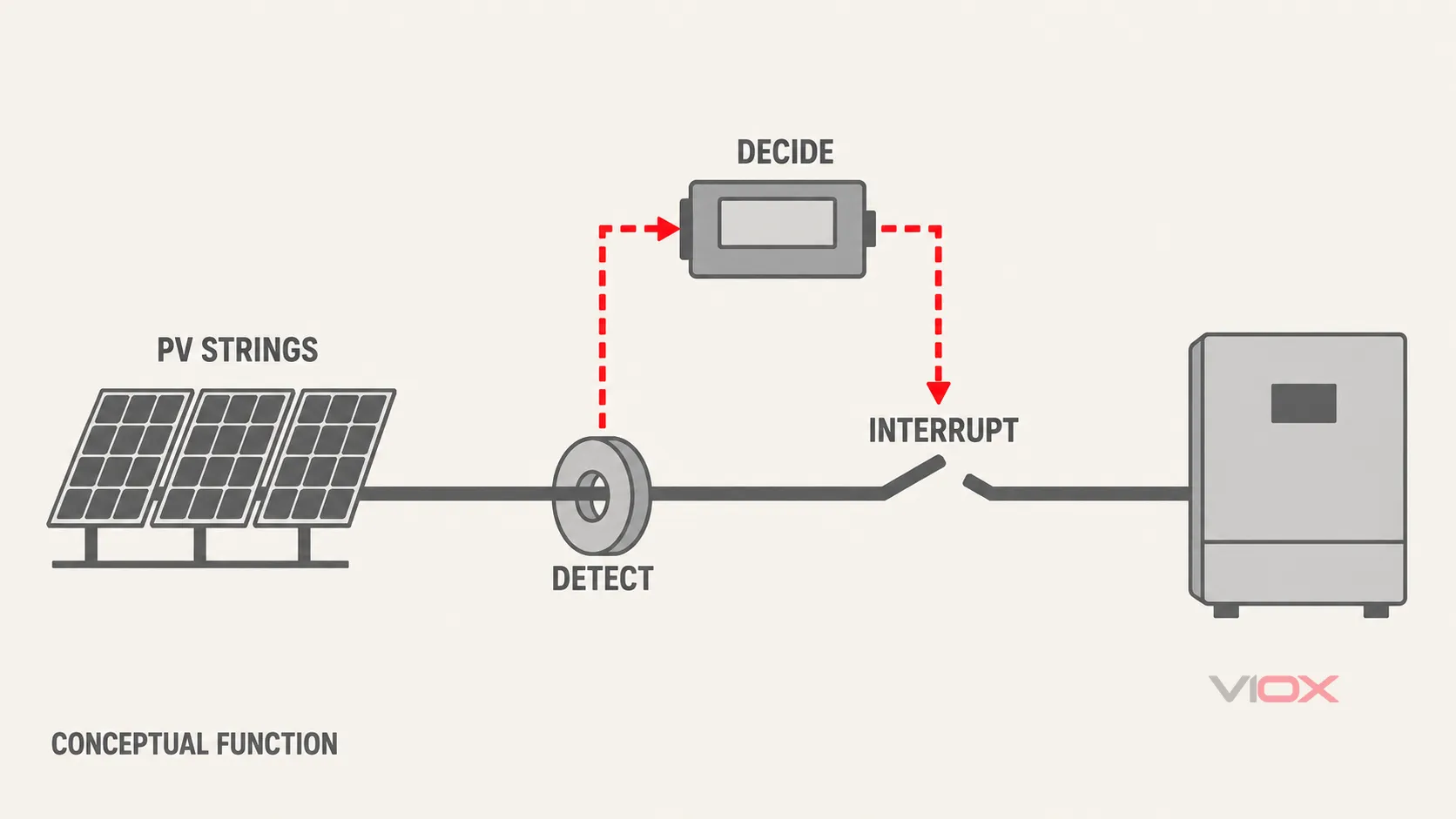
PV circuit sensing → detection decision → trip command → DC interruption → recorded status and controlled restoration.
These are functional stages, not necessarily five separate devices. Some products integrate several stages; others distribute them across the combiner and inverter. The supplier’s diagram should identify each stage and its dependencies.
At the sensing stage, request the supported string arrangement and operating range. At the decision stage, identify the detector model, relevant firmware, and evaluated configuration. At the interruption stage, identify the exact device and the current paths it opens.
For any electrically operated interrupter, verify PV DC suitability, maximum voltage, current duty, pole arrangement, and the manufacturer’s permitted use. A coil-voltage label or nominal current rating alone does not establish interruption performance. Overcurrent coordination must still be reviewed separately.
Record what happens if auxiliary power disappears, a trip wire opens, communications fail, or the interrupter does not reach its commanded state. Ask whether protection depends on a local wired command, an internal connection, or a communications link. Specify required supervision and failure responses through the project design; do not assume that loss of power or communications always produces a safe open state.
Opening an output path can stop a series arc only where that action interrupts the current sustaining it. Sunlit PV modules and other upstream parts can remain energized. The protected zone and the maintenance-isolation boundary must therefore be shown separately.
The functional illustrations in this guide are conceptual. They do not establish terminal connections, product construction, or a tested protection zone.
Keep Strings, Detection Channels, and Switched Groups Separate
Three counts describe different capabilities:
| Field | What it describes | What it does not establish |
|---|---|---|
| Input strings | PV circuits entering the box | Number of independent arc-detection channels |
| Detection channels | Signal paths evaluated by the arc-detection system | Automatic identification of the exact faulty connector or string |
| Switched groups | Circuits interrupted together after a command | Detection selectivity or coverage of every conductor section |
A box with individual string-current readings may still use a different architecture for arc detection. Ask for the mapping among input terminals, ordinary monitoring sensors, arc-detection channels, and interruption devices. Count a monitoring channel as an arc channel only when the equipment documentation explicitly establishes that role.
Compare String-Level and Common-Output Sensing
With string-level sensing, the system evaluates separate incoming circuits. With common-output sensing, the signal represents combined circuits. Either description is incomplete without supported topology, channel mapping, and fault-response documentation.
More sensors alone do not guarantee selective operation. In Sandia’s crosstalk research, arc-related signals coupled into an unfaulted parallel string and could trigger its detector in the configurations tested. The practical procurement question is therefore whether the quoted system has evidence for its claimed detection and localization behavior with the proposed parallel strings and inverter. The research does not establish the behavior of every current product.
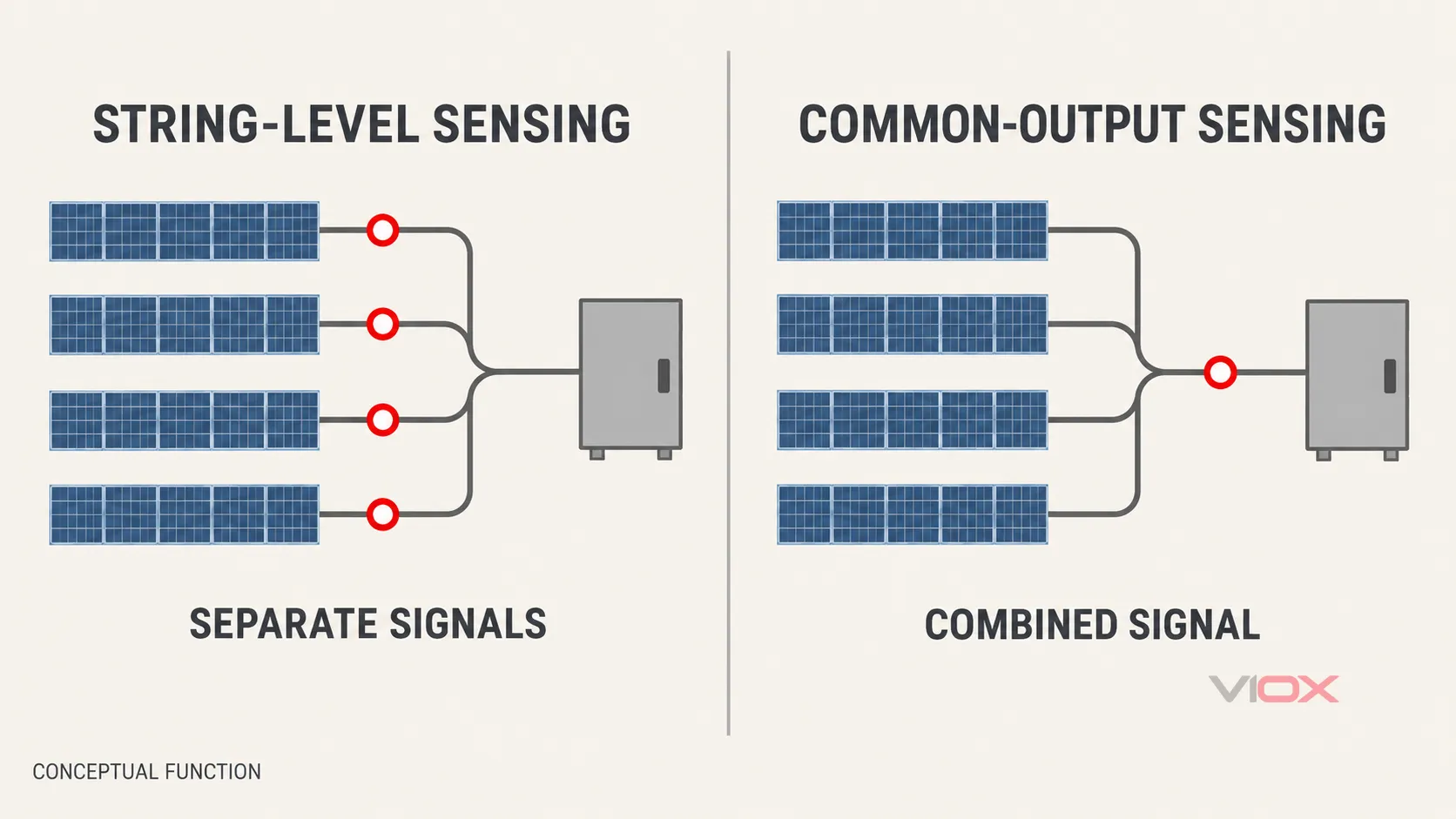
Ask the supplier to distinguish three outputs: detection of an arc event, identification of a channel, and selective interruption of the affected circuit. A product may provide the first without providing all three.
Draw the Covered Circuit Sections
Mark the proposed protection on the single-line diagram from the modules through string cables, branch connections, combiner circuits, output cables, and inverter inputs. Request explicit inclusion or exclusion of each section.
Do not infer coverage from the detector’s physical location. A combiner-mounted detector’s documented zone may differ from the enclosure boundary. An inverter-mounted detector may cover upstream circuits, but only within its evaluated configuration. Ask separately about output-cable arcs, combined strings, module-level electronics, and changes to the inverter or cable layout.
Illustrative Example: Eight Strings Do Not Mean Eight Independent AFCIs
Consider a proposed box with eight incoming strings and two outputs, each output combining four strings. This is an illustrative specification exercise, not a tested installation or a model recommendation.
Suppose the supplier proposes one arc-detection channel on each combined output. The schedule would show:
- eight incoming strings;
- two arc-detection channels;
- four strings represented by each channel;
- switched-group count and trip extent still to be confirmed.
If one common interrupter opens both outputs, an event may remove all eight strings from service. If the design has separate interrupters, the supplier must identify whether one output group can be opened independently and whether that action meets the documented protective function.
Now consider eight separately sensed inputs with one common output interrupter. The additional sensing paths do not change the fact that a trip opens a common group. Whether the detector identifies the affected string still requires supporting evidence.
The selection result is a completed allocation schedule, not a claim that either arrangement is universally better. Confirm that the inverter permits the proposed combining arrangement before evaluating the AFCI function.
Check Whether Inverter-Integrated AFCI Already Meets the Project Need
An external AFCI solar combiner box is not automatically necessary whenever the inverter has, or lacks, an AFCI label. Review the complete protection architecture.
Obtain the inverter manufacturer’s supported string count per input, channel allocation, covered circuit sections, permitted external combiners, relevant firmware, and interruption behavior. Then compare those documents with the proposed array and the project’s applicable requirements.
| Existing architecture | Selection response |
|---|---|
| Inverter documentation covers the intended strings, combining arrangement, and required circuit sections | Review whether an ordinary combiner can serve the collection and conventional protection duties without adding a separate arc-protection system |
| External combining changes the inverter’s permitted input arrangement or exceeds its documented limits | Resolve the topology or select an evaluated alternative before procurement |
| The project needs a protection zone or alarm function not provided by the inverter’s documented configuration | Review an external or distributed system with evidence for that specific requirement |
| Two arc-protection systems are proposed on the same circuits | Request a compatibility and trip-response review; do not assume that adding a second detector improves the overall result |
For installation-code and product-standard context, use the separate PV DC arc-fault protection guide. The decision here is whether the chosen combiner fits the documented system.
Turn Project Inputs into a Combiner Specification
Start with the array drawings, module data, inverter instructions, cable schedule, local requirements, and operating environment. Each input should produce a defined requirement and a document to verify it.
| Project input | Requirement to specify | Evidence to request |
|---|---|---|
| Maximum array voltage at the lowest design temperature | Voltage suitability of the complete assembly, detector interfaces, interruption devices, and insulation system | Exact-model ratings and permitted circuit arrangement |
| String operating and short-circuit currents; parallel-source contribution | Supported sensing range, conductor and bus duty, overcurrent coordination, and interruption duty | Rating schedule, protection design, and documented operating limits |
| Strings, combined groups, outputs, and inverter inputs | Input/output topology, detection-channel allocation, and switched groups | Single-line diagram plus channel-to-circuit schedule |
| Circuit sections requiring arc protection | Defined covered zone and stated exclusions | Coverage drawing tied to the evaluated configuration |
| Inverter, optimizers, or other module-level electronics | Supported equipment combinations and operating conditions | Compatibility instructions or applicable evaluation evidence |
| Required response after detection | Trip extent, interruption device, status feedback, and permitted restoration | Functional diagram and sequence of operation |
| Auxiliary power and communications | Supply source, supervision, alarm interface, and response to loss of either service | Control-power and failure-response documentation |
| Outdoor exposure and enclosure temperature | Environmental protection, thermal limits, condensation strategy, and installed cable-entry requirements | Assembly environmental ratings and installation instructions |
| Target market and project approval route | Applicable product evidence and installation acceptance requirements | Exact-model certificates/listing records and project review documents |
Use the combiner protection-design guide for coordination of fuses, DC switches, breakers, and SPDs. Their roles remain separate from arc detection. A trip-controlled device can participate in interruption when suitable for the evaluated system; ordinary overcurrent protection alone does not establish arc detection.
Environmental selection also extends beyond an enclosure’s IP label. Verify the complete installed assembly, including entries, seals, exposure, heat, and service access. The PV combiner enclosure-selection guide provides the wider enclosure context.
Verify Evidence for the Complete Configuration
IEC 63027:2023 addresses PV DC arc detection and optional interruption within its equipment scope, with series-arc detection tests and interruption-response evaluation. Its published scope extends to PV source circuits up to 1,500 V DC. That limit is the standard’s scope, not a rating granted to every product tested against it.
Use the applicable standard and classification to request evidence for the supplied function. Where the project uses UL 1699B, obtain the relevant listing or certification record and its model/configuration limitations. Installation requirements come from the project’s adopted rules and approval process; a product-standard reference alone does not make AFCI mandatory everywhere.
Review three evidence levels:
- Components: detector, interruption device, fuse equipment, SPD, and other constituent parts, as applicable.
- Assembly: the configured combiner’s electrical, environmental, and functional requirements.
- System: protected circuits, inverter interface, trip action, auxiliary services, and permitted operating configuration.
An approved detector plus an approved DC switching device does not automatically establish a verified combined function. Likewise, a certificate for one model or configuration does not automatically cover changes to channel allocation, interruption hardware, auxiliary supply, or firmware.
Request documents naming the exact model and configuration, issuing organization, relevant standard and edition, scope, conditions, and restrictions. Ask whether later substitutions require renewed review. Keep contractual claims proportional to the available evidence: series-arc evaluation does not establish protection against every parallel arc, ground fault, overheating connection, or fire scenario.
Copy-Ready AFCI Combiner Box RFQ
Send the following fields with the project drawings. Require the supplier to complete missing items rather than responding only with a voltage rating and the word “AFCI.”
Project and destination market:
Applicable installation requirements and approval route:
Maximum corrected PV voltage:
String operating current and short-circuit current:
Available parallel-source/fault contribution:
Number of input strings and output circuits:
Strings combined per output / inverter input:
Inverter and module-level electronics models:
Required covered circuit sections:
Arc-detection channels and input allocation:
Required event/channel identification:
Switched groups and trip extent:
Interruption device and declared PV DC duty:
Auxiliary supply and response to power loss:
Trip interface and response to communication failure:
Status feedback, alarm output, and event records:
Permitted reset/reconnection process:
Outdoor exposure, temperature, altitude, and enclosure needs:
Exact model, firmware, and configuration identifiers:
Component, assembly, and arc-function evidence:
Approved functional verification and handover documents:
Permitted substitutions and change-review requirements:
Evaluate offers against the same completed schedule. Treat missing coverage, unexplained interruption duty, or mismatched evidence as unresolved technical items before approving the order. A lower price is not a comparable offer when one supplier quotes detection only and another quotes a documented interruption system.
Agree the Handover Records Before Ordering
Include the final single-line and functional diagrams, channel schedule, parts/configuration list, firmware identification, certificates or test evidence, installation limitations, and operating instructions in the purchase requirements.
Specify an equipment-approved functional verification method and records for trip indication, commanded interruption, status feedback, and restoration. Do not create an improvised live DC arc as a site acceptance test. Field verification must follow the equipment instructions and the project’s qualified electrical-work procedure.
Set the permitted reconnection process from those same documents. An available remote-reset command does not establish permission to re-energize a suspected damaged circuit. Record event retention and the investigation required before restoration.
When reviewing VIOX’s published PV combiner box range, confirm each configuration against its own documentation. A conventional VIOX combiner must not be specified as an AFCI assembly without explicit exact-model evidence. Send the completed requirements to [email protected] for a model-specific discussion, with the arc-protection requirement identified separately from ordinary string collection and protection.