On this page
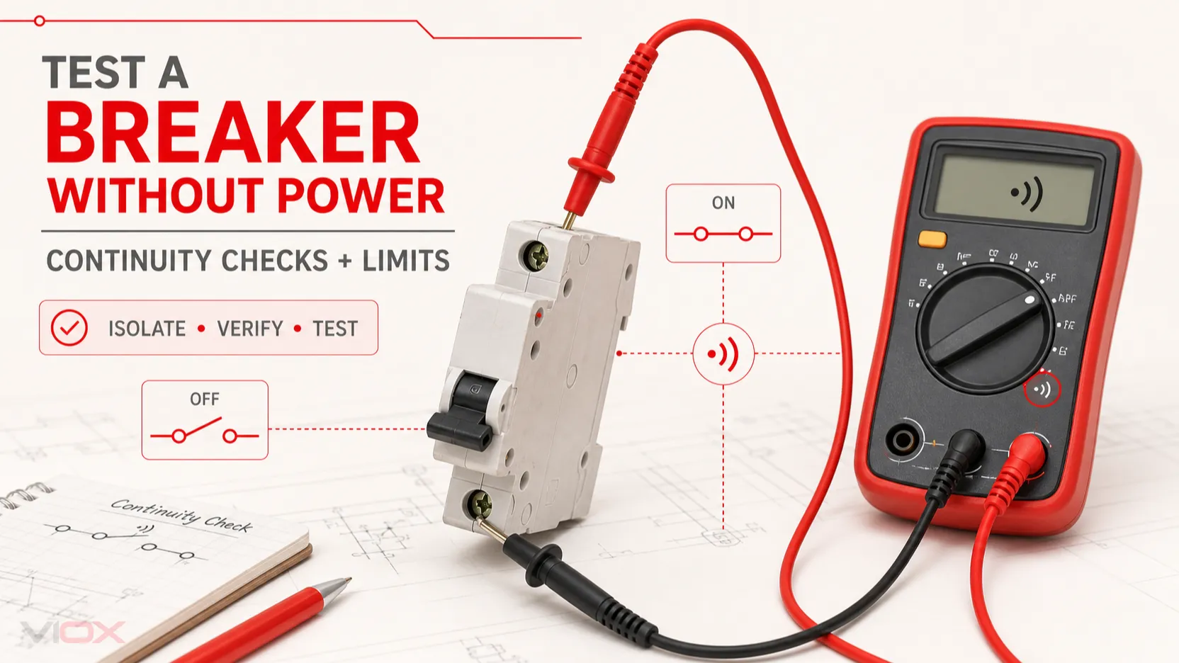
You can test a circuit breaker without power by checking its condition, operating its handle, and measuring continuity across an electrically isolated breaker. A basic thermal-magnetic breaker should show a closed path when it is reset and switched ON, and an open path when switched OFF.
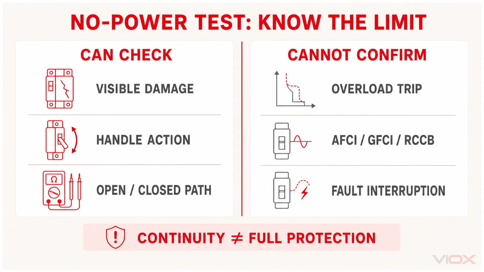
However, this is only a contact and mechanism check. It does not prove that the breaker will trip correctly during an overload or short circuit. It also cannot verify the electronic ground-fault or arc-fault protection in a Ground-Fault Circuit Interrupter (GFCI), Arc-Fault Circuit Interrupter (AFCI), dual-function breaker, Residual Current Circuit Breaker (RCCB), or Residual Current Breaker with Overcurrent protection (RCBO).
Safety boundary: Continuity and resistance modes must never be used on an energized circuit. Opening a panel, disconnecting conductors, or removing a breaker can expose live service parts even when the main breaker is OFF. Those tasks belong to a qualified electrician using an appropriate isolation, lockout/tagout, and absence-of-voltage procedure.
Key Takeaways
- A no-power test can check visible damage, handle action, and whether isolated contacts open and close.
- Prove the equipment is de-energized before touching conductors or changing the meter to continuity or resistance mode.
- Isolate the breaker from connected wiring so parallel paths do not create a misleading continuity reading.
- ON should produce continuity; OFF should produce an open-circuit indication.
- A continuity beep does not prove the breaker’s trip curve, interrupting capacity, calibration, or electronic protection.
- GFCI, AFCI, RCCB, RCBO, and dual-function test buttons generally require correct installation and an energized supply; follow the specific manufacturer’s instructions.
- Replace a breaker with burning, cracking, melting, severe corrosion, a loose mechanism, or unreliable contact action rather than treating a continuity result as approval for reuse.
What a No-Power Breaker Test Can—and Cannot—Confirm
| Check | What it can reveal | What it cannot prove |
|---|---|---|
| Visual inspection | Cracking, scorching, melting, corrosion, damaged terminals | Internal calibration or future fault interruption |
| Handle operation | Whether the mechanism resets, latches, and changes position | Correct thermal or magnetic trip timing |
| Continuity in ON | Whether the main contact path is closed at the meter’s test current | Low resistance under load or reliable fault clearing |
| Open circuit in OFF | Whether the main contact path opens | Required isolation distance or interrupting performance |
| Test button with no supply | Usually nothing conclusive for electronic or residual-current protection | GFCI, AFCI, RCCB, RCBO, or dual-function operation |
This distinction is the core of the diagnosis: a breaker can pass continuity and still be unsuitable for service. A handheld multimeter applies only a small test signal. It does not reproduce rated load current, overload heating, instantaneous magnetic operation, an arc-fault signature, residual-current imbalance, or a high-energy short circuit.
Before Testing: Isolate the Breaker and Verify Zero Voltage
Turning a breaker handle OFF is not the same as proving that the equipment is safe to touch. Backfeed, an incorrectly identified circuit, a generator, solar or battery equipment, a shared source, or wiring errors can leave voltage present.
For U.S. workplaces, OSHA 29 CFR 1910.333 requires a qualified person to use test equipment to verify that exposed circuit elements and equipment parts are de-energized and to check for voltage from induced or unrelated backfeed sources. De-energized fixed equipment that has not been locked or tagged as required must be treated as energized.
Before a bench continuity test, the qualified person should:
- identify every possible energy source;
- open the proper disconnecting means rather than relying on a control switch;
- apply the required lockout/tagout controls;
- verify that the equipment cannot restart;
- prove absence of voltage with suitable test equipment at all relevant points;
- isolate the breaker from the panel and connected circuit according to the equipment instructions.
Do not interpret a non-contact voltage indicator, a dark pilot light, or a power outage as proof of zero voltage. OSHA has specifically explained that an installed LED-type indicator can be a redundant indication but does not replace appropriate test equipment for verification of de-energization.
Tools for a De-Energized Continuity Test
- a digital multimeter with continuity and resistance functions;
- intact, properly rated test leads;
- the breaker manufacturer’s instructions or product data;
- a safe, electrically isolated work area;
- labels or photographs to preserve the original conductor and terminal identification;
- appropriate personal protective equipment and isolation equipment for the qualified person performing the work.
The multimeter’s continuity threshold varies by model. A beep means the measured resistance is below that meter’s threshold; it does not mean the breaker has zero resistance. Fluke’s continuity guidance explains that the meter supplies a small current to determine whether a path is open or closed and that continuity testing should only be attempted when voltage is not present.
How to Test a Circuit Breaker for Continuity
The following method applies to a basic, electrically isolated thermal-magnetic breaker. It is not a live-panel procedure.
1. Inspect the Breaker Before Connecting the Meter
Do not continue testing if you find:
- a cracked or distorted case;
- melted plastic or scorch marks;
- a burned odor;
- severe terminal discoloration;
- corrosion or water contamination;
- loose parts or a handle that does not align correctly;
- damage at the bus connection or mounting interface.
Visible heat or arc damage is a replacement and panel-inspection issue, not a reason to rely on a favorable continuity result.
2. Reset and Operate the Handle
If the breaker is in a tripped position, move the handle fully to OFF before attempting to reset it to ON. It should operate positively and remain in the selected position. A handle that will not latch, feels unusually loose, binds, or produces inconsistent contact readings indicates a mechanical problem.
If the only issue was an ordinary trip in an installed circuit, see the VIOX guide on how to reset a circuit breaker before assuming the device has failed.
3. Check the Multimeter and Leads
Set the meter to continuity or its lowest appropriate resistance range. Touch the probes together and observe the display and beeper. This establishes the resistance of the leads and confirms that the meter responds before testing the breaker.
If the meter does not respond consistently with the probes shorted together, stop and correct the meter, lead, battery, or setup problem.
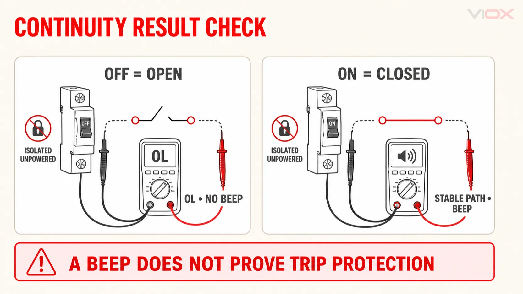
4. Test the Breaker in the OFF Position
Place one probe on the isolated line-side contact and the other on the isolated load terminal for the pole being tested. With the handle OFF, the meter should indicate an open circuit—commonly OL, an out-of-range indication, or no continuity tone.
Continuity while the handle is OFF is an abnormal result for a standard breaker contact path. Recheck that the probes are on the correct points and that the breaker is completely disconnected from parallel wiring. If the result remains, remove the breaker from service.
5. Test the Breaker in the ON Position
Move the handle to ON and measure across the same line and load points. The meter should indicate a closed path, usually with a continuity tone and a resistance near the shorted-lead reading.
If ON remains open or the reading changes when the handle is lightly operated, the contact or mechanism may be damaged. Do not attempt to repair a sealed miniature or residential breaker; replace it with the exact approved type and rating after the circuit and panel have been inspected.
6. Repeat for Each Pole
For a two-pole or multi-pole breaker, test each pole separately using the corresponding line and load contacts. Confirming continuity on each pole does not prove that the common-trip mechanism or simultaneous opening action meets its specification.
How to Interpret the Results
| OFF result | ON result | Interpretation | Next step |
|---|---|---|---|
| Open | Closed and stable | Contact path switches normally | Do not treat this as proof of trip protection; complete all required checks |
| Open | Open | Breaker contact path does not close, wrong test points, or mechanism problem | Recheck isolation and test points; replace if confirmed |
| Closed | Closed | Contacts may be welded, wrong test points, or a parallel circuit is present | Confirm full isolation; remove from service if breaker remains closed in OFF |
| Intermittent | Intermittent | Unstable contact, damaged mechanism, contaminated points, or poor probe contact | Recheck setup; replace if instability follows the breaker |
| Closed but clearly higher/unstable than lead reference | Closed | Possible contact issue, but a normal DMM is not a precision contact-resistance instrument | Use professional assessment; do not assign a universal ohm limit |
Avoid declaring a breaker good based on a specific handheld-meter value such as “below 1 ohm.” Lead resistance, probe pressure, meter resolution, breaker design, and test-point condition all affect the reading. Precision contact-resistance work uses specialized low-resistance equipment and a controlled procedure.
How to Test a Circuit Breaker Without a Multimeter
Without a multimeter, you can perform only a limited screening check while the equipment is de-energized:
- look for cracks, heat damage, discoloration, corrosion, or a burned odor;
- move the handle through OFF, reset, and ON positions;
- check whether the handle latches normally;
- inspect the terminal and mounting contact for obvious damage;
- compare the mechanical feel with an identical known-good device only when both are safely isolated.
These observations can identify a breaker that should be replaced, but they cannot confirm that an apparently normal breaker closes electrically. Do not create a deliberate short circuit, bypass protection, swap breakers casually inside a panel, or energize exposed equipment as a substitute for proper testing.
When the Breaker Should Be Replaced
Remove the breaker from service when the qualified assessment confirms any of the following:
- it remains electrically open in ON after the setup and test points are verified;
- it remains electrically closed in OFF after all parallel paths are removed;
- contact action is intermittent or the handle will not latch reliably;
- the case, terminals, or bus connection show burning, melting, cracking, or significant corrosion;
- the breaker is the wrong type for the panel or application;
- the manufacturer’s required test fails;
- it has interrupted a fault or experienced damage for which the manufacturer requires inspection or replacement;
- the panel connection, conductor terminal, or surrounding equipment has heat or arc damage.
Repeated tripping alone does not prove the breaker is defective. An overload, short circuit, ground fault, arc fault, damaged conductor, loose connection, or faulty appliance may be causing a correctly operating breaker to trip. Diagnose the circuit before installing a replacement, and never increase the ampere rating simply to prevent tripping.
Why GFCI, AFCI, RCCB, and RCBO Protection Cannot Be Verified Without Power
A standard continuity test checks only the main contact path. Electronic and residual-current protective devices contain sensing and trip functions that require a different test.
GFCI and AFCI Breakers
Schneider Electric states that its AFCI push-to-test method requires the breaker to be installed in an energized load center or panel with the required neutral connection. Its GFCI troubleshooting guidance likewise begins by confirming correct installation in an energized panel. A no-power continuity test cannot simulate the electronic ground-fault or arc-fault detection function.
For a comparison of these protections, see GFCI breaker vs. AFCI breaker.
RCCB and RCBO Devices
An RCCB test button creates an intentional imbalance through an internal test circuit. Its operation depends on the device design, supply connection, voltage, and manufacturer’s instructions. With the supply absent, pressing the button normally cannot verify residual-current tripping performance.
Use the visible test button only as directed by the manufacturer, and use appropriate residual-current test equipment when a measured trip-current or trip-time verification is required. The VIOX RCCB functionality maintenance guide covers that separate intent.
When Professional Breaker Testing Is Required
Continuity is appropriate for a simple open/closed screening check. It is not a substitute for professional testing when the decision depends on protection performance.
Depending on the breaker type, application, manufacturer, and maintenance program, qualified technicians may use:
- calibrated primary-injection testing to evaluate the complete current path and trip response;
- secondary-injection or manufacturer-specific test equipment for compatible electronic trip units;
- low-resistance measurement for main contacts;
- insulation-resistance testing under an approved procedure;
- voltage-drop or thermal assessment under controlled load;
- GFCI, RCD, RCCB, or RCBO test equipment for trip current and time;
- manufacturer-prescribed inspection after a high-fault event.
These methods require device-specific limits and procedures. They should not be reduced to a generic pass/fail number in a homeowner continuity guide.
Quick Decision Guide
| Situation | Appropriate action |
|---|---|
| Power is unavailable and breaker remains installed | Limit checks to accessible visual and handle observations; do not open the panel without qualification |
| Basic breaker is safely removed and isolated | Perform OFF/open and ON/closed continuity checks |
| Breaker passes continuity but trips in service | Investigate load, wiring, terminals, and fault conditions |
| GFCI/AFCI/RCCB/RCBO test button is being checked | Restore the correct installed and energized test conditions specified by the manufacturer |
| Breaker has burn, melt, crack, or bus damage | Remove from service and inspect the associated panel and conductors |
| Trip performance must be certified | Use the manufacturer-defined or professional injection/test procedure |
Frequently Asked Questions
Can you test a circuit breaker without power?
Yes. On an electrically isolated basic breaker, you can inspect the device, operate the handle, and check whether its main contacts are open in OFF and closed in ON. You cannot verify overload, short-circuit, arc-fault, or ground-fault trip performance this way.
How do you test a circuit breaker for continuity?
After a qualified person has isolated the breaker and verified zero voltage, place the meter across the corresponding line and load contacts. OFF should read open; ON should show a stable closed path. Test each pole separately on a multi-pole breaker.
Can I test continuity with the breaker still connected?
The breaker and circuit must be de-energized, and the breaker must be isolated from connected wiring that could create a parallel path or backfeed. Testing an installed, connected breaker can produce a misleading result and may expose the tester to hazardous parts.
Does a continuity beep mean the breaker is good?
No. It only shows that the measured path is below the meter’s continuity threshold. It does not prove contact condition under load, thermal or magnetic calibration, interrupting capacity, common-trip action, or electronic protection.
How can I test a breaker without a multimeter?
You can inspect for visible damage and check whether the handle resets and latches. These checks may identify an obviously bad breaker, but they cannot confirm electrical continuity or protective performance.
How do I test a GFCI breaker without power?
You can inspect its case and basic mechanical/contact action, but you cannot verify the GFCI sensing and tripping function without the correctly installed, energized conditions specified by the manufacturer. Use the test button and any instrumented test only according to the device instructions.
Can I press the AFCI or GFCI test button while the power is off?
You can physically press it, but a no-power result is not a valid functional test for devices whose test circuit requires an energized panel and neutral connection. Follow the exact manufacturer’s test procedure.
Should I replace a breaker that passes continuity but looks burned?
Yes, a burned, melted, cracked, or severely corroded breaker should not be returned to service simply because it passes continuity. The panel connection, conductor, and cause of damage also need inspection.
Final Answer
The correct way to test a basic circuit breaker without power is to first establish a verified de-energized and isolated condition, then combine visual inspection, mechanical operation, and ON/OFF continuity measurements. The expected pattern is simple: open in OFF and closed in ON.
Treat that result as a screening test—not a certification of protection. If the breaker is damaged, behaves inconsistently, serves a critical application, or includes GFCI, AFCI, RCCB, RCBO, or electronic trip functions, use the manufacturer’s energized test procedure or qualified professional test equipment.