On this page
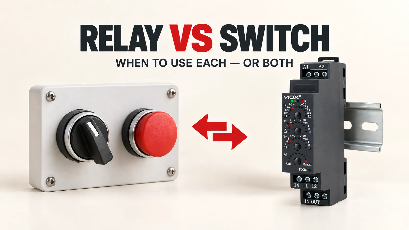
Use a control switch when a person or machine mechanism can directly operate a suitably rated control circuit. Use a relay when an electrical signal must operate contacts remotely, multiply contacts, interface circuits, or implement simple control logic. Use both when a manual switch supplies the command and a relay performs the electrically operated switching stage.
Neither device automatically provides overcurrent protection, overload protection, or safe isolation. Those functions may require a circuit breaker, fuse, overload relay, contactor, switch-disconnector, or another device selected for the actual circuit.
Relay vs Switch: Quick Decision Matrix
| Decision point | Control switch | Control relay | Use both |
|---|---|---|---|
| What changes the contact state? | Direct human or mechanical actuation | An electrical input energizes or controls the relay | The switch creates the command; the relay creates the electrically operated output |
| Local manual command | Usually the simplest choice | Not sufficient by itself if a person needs an operator | Appropriate when the manual command must enter an automated or remote circuit |
| PLC, sensor, timer, or remote command | Not normally the final interface unless the source physically operates the switch | Natural fit when the input and relay are compatible | Useful when local manual control and automatic electrical control must coexist |
| Multiple NO/NC output paths from one command | Possible with a suitable multi-contact switch | Common reason to use a relay with multiple contacts | Useful when a manual operator must create several electrically separated control paths |
| Control-voltage or output-interface problem | Does not by itself translate an electrical command | May provide an interface when ratings and insulation are verified | Switch commands the relay coil; relay contacts operate the next circuit |
| Final power load | Only if the exact switch is declared for that load duty | Only if the exact relay contacts are declared for that load duty | A relay may command a contactor when neither control device should switch the final load |
| Protection or safe isolation | Not assumed | Not assumed | Separate protective or disconnecting equipment may still be required |
The practical question is therefore not “Which component is better?” It is:
How should the command be created, how should it be transferred, and which device is declared to switch the actual load?
What “Switch” Means in This Comparison
This article compares a relay with an industrial control switch—for example, a push button, selector switch, foot switch, or position-operated control switch. These devices change one or more control contacts through direct human or mechanical action.
The word switch can also describe an isolator, load-break switch, transfer switch, household wall switch, or semiconductor switching element. Those products have different functions and product-standard boundaries, so they cannot be combined into one universal relay comparison.
The same caution applies to relay. This page concerns control relays and elementary electromechanical relays used to switch control signals or declared loads. Protective relays, safety relays, timer relays, monitoring relays, and solid-state relays require additional selection rules.
For the broader control-relay mental model, see What Is a Control Relay?. For operator behavior, positions, and contact blocks, see What Is a Selector Switch?.
The Core Difference Is Actuation, Not Contact Shape
A mechanical control switch and an electromechanical relay can both contain normally open (NO), normally closed (NC), or changeover contacts. They may even use the same SPST, SPDT, DPST, or DPDT contact language. The important difference is what causes those contacts to change state.
- A control switch is acted on directly by an operator or machine mechanism.
- An electromechanical relay changes state when its coil receives a compatible electrical input.
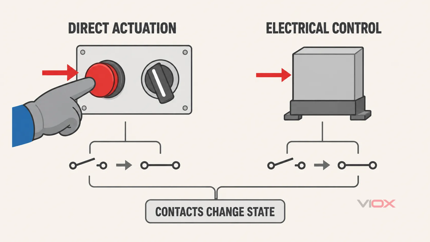
This leads to different circuit roles. A switch is often the command point—the button pressed by an operator or the position detected by a mechanism. A relay is often an intermediary that receives a command and creates one or more new contact outputs.
However, avoid four weak shortcuts:
- Switches are not always manually operated. Limit, pressure, float, and other pilot switches can be actuated by a physical condition.
- Relays do not always switch high power. A control relay may switch only a contactor coil, PLC input, indicator, interlock, or low-level signal.
- A relay is not automatically rated higher than a switch. Suitability depends on the exact contact rating and load duty, not the product name.
- A relay does not automatically provide safe isolation or circuit protection. Those conclusions require the declared product data and the complete system design.
The VIOX guide to SPST, SPDT, DPST, and DPDT contacts explains the contact forms shared by switches and relays.
Five Questions That Determine the Right Architecture
1. Where does the command come from?
If the command is a person turning a selector or pressing a button, a control switch is the natural input device. If the command comes from a programmable logic controller (PLC), sensor, timer, monitoring device, or remote circuit, a relay may be the appropriate electrically operated interface.
A machine can require both. An AUTO/MANUAL selector, for example, can determine which command path is enabled while a relay performs the downstream electrical switching.
2. Must control occur remotely or automatically?
A directly operated switch requires physical actuation at its location. A relay allows an electrical signal from another location or control system to change the output contacts.
Distance alone does not prove that a relay is required. Cable voltage drop, electromagnetic compatibility, control voltage, fault behavior, and installation rules must be evaluated. The useful principle is that the relay can place the electrically operated contact stage near the controlled circuit while the initiating command originates elsewhere.
3. How many contact paths must one command control?
A suitable multi-contact switch can operate several contacts mechanically. A relay can also operate multiple NO, NC, or changeover contacts from one coil command. The choice depends on whether those paths should follow a direct operator action or an electrical signal.
If the design needs additional contacts beyond those available on the initiating device, a relay may provide contact multiplication. Every pole must still be verified for its individual load and circuit conditions.
4. What is the actual switched load?
Do not select either device from a headline ampere value alone. Identify what the contact will switch:
- a PLC input;
- an indicator or alarm input;
- a contactor or solenoid coil;
- a lamp or electronic power supply with inrush;
- a heater, motor, or other power load;
- AC or DC at the actual operating voltage.
Two contacts carrying the same steady current can experience very different making and breaking stress. Verify the manufacturer-declared load category, voltage, current, inrush or utilization data, switching frequency, and electrical endurance for the intended duty.
5. What should happen after loss of the command or control supply?
A maintained switch normally remains in its selected mechanical position until operated again. A momentary or spring-return switch returns when released. A conventional non-latching relay normally returns to its de-energized contact state when its coil supply is removed, while a latching relay behaves differently.
These behaviors affect restart, fail-state, and control-logic decisions. They do not by themselves establish a safety function. Safety-related control requires an appropriate architecture, components, diagnostics, and validation beyond an ordinary switch or control relay.
When a Control Switch Alone Is Enough
A switch alone may be appropriate when all of the following are true:
- a direct human or mechanical action is the required command;
- the switch contacts are explicitly rated for the controlled circuit and load duty;
- the required poles, throws, and maintained or momentary behavior are available;
- remote electrical actuation, contact multiplication, or interface conversion is unnecessary;
- the complete system provides any required protection and disconnection separately.
Examples include a selector switch sending a control input to a PLC or a suitably rated push button operating a compatible control-circuit load. This does not mean that an ordinary panel operator should directly switch a motor or other demanding power load.
When a Relay Is the Better Control Element
A relay may be appropriate when the contacts must respond to an electrical command rather than direct physical action. Common decision reasons include:
- a PLC, sensor, timer, or remote circuit provides the command;
- one input must create multiple contact outputs;
- the source output and controlled device need a verified interface stage;
- replaceable contact outputs are desired between a controller and downstream control devices;
- simple hardwired permissive, interlock, or status logic is required.
“Interface” is not a blanket guarantee of compatibility or galvanic separation. The relay coil must match the source, the contacts must match every switched load, and the declared insulation data must support the circuit arrangement.
When the Circuit Needs Both a Switch and a Relay
Many industrial circuits use a switch and relay as complementary devices rather than alternatives:
Operator or machine action
           ↓
  Control switch contact
           ↓ command
      Relay coil/input
           ↓ action
   Relay output contact(s)
           ↓
Downstream control device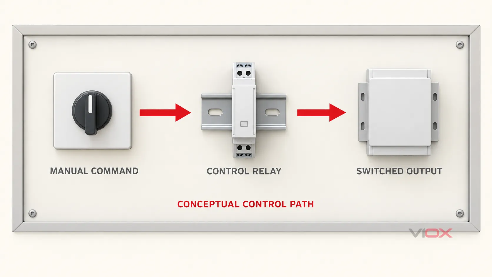
Consider a conceptual panel in which an operator selects RUN. The selector switch closes a control path that energizes a compatible relay coil. One relay contact sends a run request to a downstream control device, while another provides a separate indication or interlock path.
This architecture can provide command staging and contact multiplication, but it does not establish terminal connections, voltage compatibility, or safety performance for a real machine. Those details must come from the exact product data and system design.
When Neither Device Is the Complete Answer
The correct outcome is sometimes neither switch nor relay acting alone.
The final load requires a contactor
If the circuit must repeatedly switch a motor, heater bank, grouped lighting, or another declared power duty, a contactor may be the correct final switching element. A control switch or relay can command its coil, while the contactor’s main contacts switch the load.
The distinction is based on circuit role and declared duty, not a universal current threshold. See Contactor vs Control Relay for the power-stage boundary.
The circuit needs protection
A control switch and an ordinary relay generally do not replace the protective device required for short-circuit or overload conditions. Protection must be selected and coordinated for the conductors, load, switching devices, and available fault conditions.
The circuit needs a disconnecting or isolating function
Opening a control contact is not automatically equivalent to disconnecting or isolating the power circuit. If the task is safe disconnection, maintenance isolation, or load breaking, select equipment that is declared for that function and follow the applicable installation rules.
Compare Ratings on a Common Basis
The component names do not provide enough information for selection. Compare the actual circuits and ratings.
| Specification | Control switch | Control relay | Why it changes the decision |
|---|---|---|---|
| Actuation | Operator or mechanism, including maintained or momentary action | Coil or defined electrical input | Determines how the command is created |
| Contact form | Required NO, NC, or changeover blocks and number of poles | Required NO, NC, or changeover contacts and number of poles | Determines available control paths |
| Contact duty | Voltage, AC/DC, load type, utilization category where declared, making/breaking stress | The same contact-duty checks, independent of the coil rating | Prevents selection from a headline current alone |
| Input requirement | Mechanical force, travel, key/handle/operator arrangement as applicable | Coil voltage, AC/DC type, frequency or polarity where applicable, pickup and release behavior, power demand | Determines compatibility with the command source |
| Operating pattern | Frequency of human or machine actuation | Electrical command rate and relay operating duty | Affects endurance and thermal suitability |
| Environment | Mounting, enclosure, ingress exposure, temperature, vibration and access | Mounting, socket, spacing, temperature, vibration and serviceability | Determines physical integration and product suitability |
| Failure behavior | Maintained, spring-return, contact state, mechanical failure considerations | De-energized state, latching behavior if applicable, contact or coil failure considerations | Supports control-state and restart analysis |
Keep a relay’s coil and contacts separate
A relay has at least two rating domains:
- The coil or input rating tells you how the relay is actuated.
- The contact ratings tell you what each output contact may switch under declared conditions.
A 24 V DC coil marking does not mean the contacts are limited to 24 V DC, nor does it prove they can switch a particular AC or DC load. Conversely, a contact rating does not tell you whether a PLC output can supply the coil’s pickup demand or tolerate its switching transient.
Standards define product scope, not application approval
IEC 60947-5-1:2024 applies to electromechanical control-circuit devices and switching elements used for functions such as controlling, signalling, and interlocking within its stated limits. Its scope includes categories such as manual control switches and electromagnetically operated control switches.
IEC 61810-1 applies to electromechanical elementary relays incorporated into low-voltage equipment within its scope. A device’s appearance or generic name does not prove which standard applies, and citing either standard does not prove that a particular VIOX model is certified or suitable for a specific circuit.
Verify the exact datasheet, declaration, certificate where required, and complete assembly requirements before making a product-level claim.
Pre-Order Specification Worksheet
Complete these fields before comparing models:
- Command source: person, machine mechanism, PLC, sensor, timer, or remote circuit.
- Required architecture: switch, relay, both, or another switching device.
- Control supply: nominal voltage, AC or DC, frequency where applicable, polarity, and available current.
- Contact jobs: list every device or signal that each contact will switch.
- Contact arrangement: number of NO, NC, and changeover contacts; maintained or momentary behavior where relevant.
- Load duty: operating voltage, steady current, making or inrush condition, breaking condition, AC/DC type, and utilization category where declared.
- Operating pattern: expected switching frequency and required electrical and mechanical endurance.
- Physical integration: panel operator size, relay socket or mounting method, terminals, available space, indication, and service access.
- Environment: enclosure conditions, temperature, contamination, vibration, and required ingress protection at the assembly level.
- System boundaries: separate overcurrent protection, overload protection, contactor, safety function, and disconnecting means where required.
- Evidence: exact datasheet, applicable standard, approvals for the destination market, and assembly documentation.
Final Selection Rule
Choose a control switch when the circuit needs a direct local or mechanically initiated command and the switch is declared for the contact duty. Choose a relay when an electrical command must create one or more compatible contact outputs. Choose both when a manual or mechanical command must enter an electrically operated control stage.
Choose another device category when the job is power-load switching, short-circuit or overload protection, safety-related control, or power-circuit isolation. The safest specification begins with circuit role and load duty—not with the assumption that a relay is simply a “stronger switch.”
After defining the architecture, compare the relevant VIOX control and signaling devices or send the completed worksheet to [email protected] for model-level review.