On this page
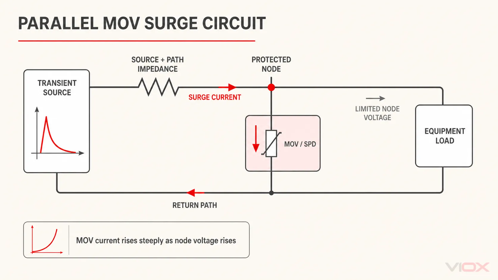
An MOV surge protector works in parallel because the metal-oxide varistor is a nonlinear shunt element. At normal system voltage, it carries only a small leakage current. When a transient raises the voltage at the protected node, MOV current rises steeply. That current flowing through the finite impedance of the surge source and supply path changes the node voltage, while the MOV limits the voltage across itself and the parallel-connected load.
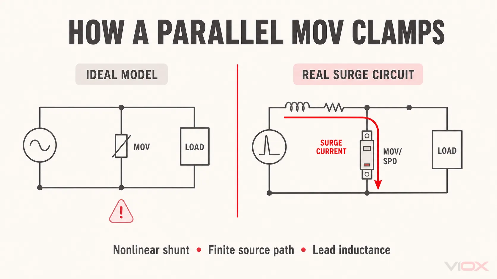
The protected load and MOV do share the same voltage at their common connection point. There is no “parallel circuit paradox.” The mistake is treating the supply as an ideal voltage source with zero impedance—or treating the MOV as a fixed resistor. Neither model represents an actual surge test or installation.
One more distinction matters: the voltage declared for the MOV or complete surge protective device (SPD) is measured at specified terminals and test conditions. The equipment may see additional voltage caused by the inductance of the SPD connection conductors and by the physical layout between the SPD and the equipment.
The Correct MOV Surge Protection Circuit
A useful circuit model contains five elements:
- a transient source;
- the source and supply-path impedance;
- the protected connection node;
- an MOV or MOV-based SPD connected across the relevant conductors;
- the protected load connected to that node.
During normal operation, the MOV branch is high impedance and does not carry load current. During a surge, its nonlinear voltage-current characteristic allows a large current through the protective branch. The current returns through another conductor—such as neutral, another phase, or protective earth—according to the SPD’s protection mode and the surge path.
This is why “the SPD sends every surge to ground” is not a complete explanation. A line-to-neutral MOV conducts between line and neutral. A line-to-line mode conducts between phases. A line-to-PE mode involves the protective-earth path. The complete circuit and protection modes determine where current flows.
The governing idea is simultaneous, not sequential:
- the transient attempts to raise the node voltage;
- MOV current increases as that voltage rises;
- surge current through the source and path impedance produces a voltage difference along that path;
- the MOV’s nonlinear characteristic and the source network settle at an operating point for that instant of the waveform;
- the load at the same node sees the resulting limited voltage, subject to connection and separation effects.
IEC 61643-11:2025, applied together with the common requirements in IEC 61643-01:2024, describes low-voltage AC SPDs as containing at least one nonlinear component intended to limit surge voltages and divert surge currents. IEC 61643-332:2024 addresses MOV operating theory, selection, and application principles.
Why an Ideal-Source Diagram Gives the Wrong Answer
Suppose an ideal voltage source forces exactly 1,000 V across a load and an MOV, with zero impedance anywhere in the source or conductors. Connecting a shunt MOV cannot reduce that imposed voltage. It would draw unlimited current in an idealized model, which is physically impossible.
Real transient sources are not ideal. Surge generators have defined source characteristics. Utility transformers, conductors, busbars, connections, and the surge-coupling path contribute resistance, inductance, capacitance, and wave-propagation effects. These properties limit the prospective current and influence the voltage at the SPD connection point.
The MOV also is not a switch that changes from “infinite resistance” to one fixed low resistance. Its current depends strongly and continuously on voltage. For conceptual purposes:
iMOV(t) = f[vMOV(t)]The function is highly nonlinear. A small increase in voltage in the conduction region can produce a large increase in MOV current. The relevant protective quantity is therefore a measured or declared clamping/residual voltage at stated current and waveform conditions—not a universal dynamic-resistance value.
IEEE C62.33-2016 covers test methods and performance values for MOV surge-protective components, including 8/20 surge-current ratings and clamping voltage. IEEE C62.42.2-2022 covers MOV characteristics, ratings, and application examples. These frameworks reinforce an important rule: an MOV voltage figure is meaningful only with its measurement or test conditions.
Five Voltage and Current Quantities That Must Not Be Confused
Many incorrect MOV explanations use one word—“surge voltage”—for several different quantities. Separate them before making any calculation or protection claim.
| Quantity | What it represents | What it can tell you | What it cannot tell you alone |
|---|---|---|---|
| Open-circuit impulse voltage | Voltage produced by the defined surge source with its output open | One characteristic of the test source or assumed surge environment | The voltage that will remain after an SPD conducts |
| Prospective short-circuit surge current | Current the defined surge source can deliver into a short circuit | Another characteristic of the source | The exact current through a particular installed MOV |
| Component clamping voltage | Voltage across an MOV at a specified impulse current and waveform | MOV behavior under the stated component test | Complete-SPD or equipment-terminal protection in every layout |
| SPD residual voltage, Up, or VPR | A complete-device protection quantity under its applicable framework and test | Tested or declared voltage limitation at the SPD terminals or protection mode | Additional voltage introduced by field connections and separation |
| Equipment-terminal voltage | Transient actually appearing across the protected equipment terminals | The value relevant to equipment insulation stress | It cannot be inferred from one catalogue number without installation context |
The first two describe the source. The next two describe the component or complete SPD under defined tests. The last describes the installation outcome.
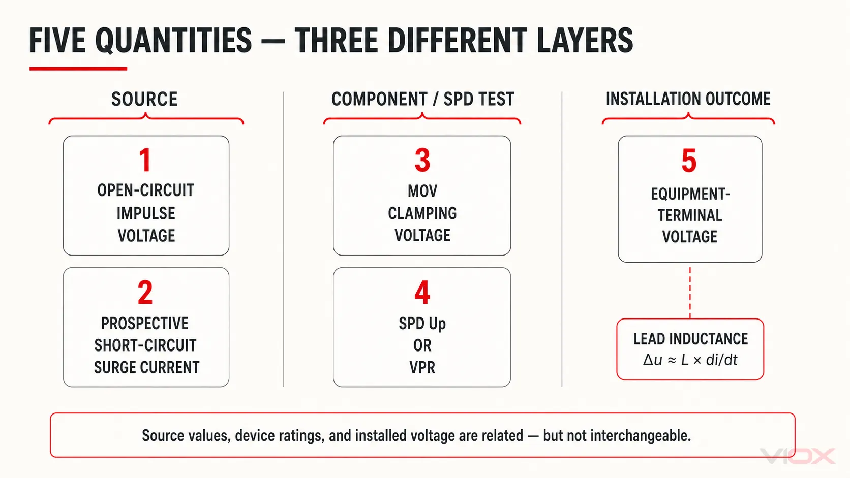
Up and VPR belong to different frameworks
In IEC-oriented documentation, Up is the declared voltage protection level of the SPD. In UL-oriented documentation, voltage protection rating (VPR) is a standardized marked rating. Both help evaluate voltage limitation, but they should not be treated as numerically interchangeable labels stripped from their respective test methods.
UL Solutions identifies VPR, maximum continuous operating voltage (MCOV), nominal discharge current (In), and short-circuit current rating (SCCR) as important SPD ratings. The SPD Uc and Up guide explains the continuous-voltage and protection-level distinction in more detail.
Why 6 kV/3 kA Is Not a Universal “2-Ohm Rule”
A combination-wave generator may be described by an open-circuit voltage and a prospective short-circuit current. Dividing 6 kV by 3 kA gives a 2-ohm ratio for that defined source condition. This is useful for understanding the generator—not for assigning a universal 2-ohm high-frequency impedance to every residential, commercial, or industrial installation.
It does not prove that:
- every building service has 2 ohms of surge impedance;
- 60 Hz available fault current can be converted into a surge impedance using one multiplier;
- a building close to a transformer necessarily has ineffective surge protection;
- breaker contact resistance should determine whether an SPD is installed on the line or load side;
- a field engineer can predict equipment-terminal voltage with a fixed MOV resistance and a simple DC voltage divider.
The surge environment, coupling path, waveform, installation geometry, and complete SPD characteristics all matter. Product selection should use the applicable declared ratings and installation instructions, not an invented “impedance budget.”
The Impedance Before the Node and the Inductance in SPD Leads Do Opposite Jobs
Two effects are often mixed together.
Source and supply-path impedance influences the incident surge
Impedance between the transient source and protected node limits prospective surge current and affects the node voltage when the MOV conducts. It is part of the reason a shunt device can limit the voltage produced by a real, finite source.
That does not make “more upstream impedance” a general installation goal. Adding arbitrary impedance can affect normal operation, fault performance, electromagnetic compatibility, and protection coordination. The source network is an input to the surge problem, not a field adjustment rule for choosing breaker location.
SPD connection inductance adds to the equipment-side voltage
The conductors connecting the distribution conductors to the SPD carry rapidly changing surge current. Their inductance produces an additional transient voltage. A useful conceptual relation is:
ΔuL ≈ Lloop × di/dtwhere Lloop is the effective inductance of the complete surge-current connection path and di/dt is the current rate of change. This is not a field calculator: conductor routing, loop geometry, mutual coupling, bends, terminals, waveform, and current sharing affect the result.
The practical consequence is reliable: excessive connection length and loop area can raise the voltage appearing beyond the SPD’s tested terminal value. NEMA’s hard-wired SPD installation guidance explains that connecting-lead inductance adds to the suppression-element voltage and degrades residual performance. UL Solutions similarly advises keeping SPD conductors as short as possible and avoiding sharp 90-degree bends where possible.
For terminal arrangements, backup protection, conductor routing, and commissioning boundaries, use the dedicated SPD wiring guide and the exact manufacturer’s instructions.
A Two-Node Model Prevents the Most Common Design Error
The SPD connection point and equipment terminals should not automatically be treated as one ideal node.
Node A: SPD connection point
At Node A, the SPD limits voltage according to its nonlinear elements, internal construction, protection mode, and applied surge. Up, VPR, or residual-voltage data describe performance at defined device terminals and test conditions.
Node B: protected equipment terminals
Node B may be separated from Node A by conductors, busbars, filters, switches, transformers, or other network elements. During a fast transient, these are not electrically invisible. The equipment-terminal voltage can differ from the SPD-terminal voltage because of inductive drops, coupling, oscillation, wave propagation, and another surge entry path such as a signal cable.
This gives a safer conceptual relationship:
equipment-terminal voltage = SPD-limited voltage + installation-dependent effectsThe sign and waveform of every contribution cannot be reduced to one universal arithmetic addition. The equation is a design reminder: a good SPD catalogue value does not compensate for poor connection geometry or an unprotected parallel entry path.
Why an MOV-Based SPD May Still Fail to Protect Equipment
If protected equipment is damaged, the correct question is not simply “Was there enough line impedance?” Check the complete protection chain.
| Check | Why it matters | Verify against |
|---|---|---|
| Continuous-voltage rating | An unsuitable Uc or MCOV can stress or disconnect the SPD during normal voltage or temporary overvoltage | System voltage, earthing arrangement, product datasheet |
| Protection modes and topology | The SPD must provide a path for the surge modes that can stress the equipment | Single-line diagram, TN/TT/IT arrangement, manufacturer configuration |
| Up or VPR | The declared protection level must support the equipment’s insulation-coordination objective | Applicable framework, equipment withstand data, design study |
| Connection length and loop area | Lead inductance can add voltage during a fast current rise | Installation instructions and panel layout |
| Short-circuit and backup protection | Internal or external disconnection must be coordinated with the available fault condition | SCCR or applicable IEC short-circuit declaration, backup fuse/breaker instructions |
| Protection status | A thermally disconnected or failed module may no longer provide its intended mode of protection | Status window, remote contact, maintenance records |
| Multiple entry paths | Power, data, control, antenna, and bonding paths can introduce different surges | Complete system architecture |
| Surge severity and coordination | No SPD guarantees zero terminal voltage or protection against every event | Risk assessment, SPD Type, coordination plan, equipment withstand |
MOV aging and end-of-life behavior are separate from the circuit mechanism explained here. For that decision, use the industrial SPD lifespan and MOV aging guide. For the MOV’s ZnO material structure and component physics, see ZnO MOV explained.
Engineering Verification Checklist
Before accepting an MOV-based SPD design, verify:
- the exact nominal and maximum continuous voltage across each protection mode;
- the earthing arrangement and conductors available at the installation point;
- Uc or MCOV and temporary-overvoltage behavior;
- SPD Type and applicable test framework;
- Up or VPR by protection mode where provided;
- In, Imax, Iimp, or other relevant discharge-current declarations;
- SCCR or the applicable IEC short-circuit withstand/current declaration, plus required backup protection;
- the shortest practical, manufacturer-compliant connection path with limited loop area;
- equipment impulse-withstand and insulation-coordination requirements;
- every power, signal, communication, and bonding path entering the protected zone;
- status indication, remote signaling, inspection, and replacement procedure.
The SPD datasheet guide provides a full rating review. When the system inputs are known, compare available VIOX surge protective devices by voltage, topology, Type, protection level, discharge-current declaration, and backup-protection requirements rather than by MOV size or a single kA number.
Frequently Asked Questions
If the MOV and load are in parallel, do they see the same voltage?
Yes—when they share the same ideal connection node. The MOV protects by changing the current drawn from a non-ideal surge source, which changes the voltage established at that node. In a real installation, the equipment may be a second electrical node because conductors and layout have impedance during a fast transient.
Does an MOV absorb the surge voltage?
No. Voltage is not absorbed. The MOV conducts surge current and dissipates some energy while limiting the voltage across its terminals. Energy and current distribution depend on the source, waveform, MOV characteristic, other protective elements, and circuit path.
Is an MOV a short circuit during a surge?
Not an ideal short circuit. It becomes much more conductive, but retains a nonlinear voltage-current characteristic and a significant residual or clamping voltage. That voltage depends on the impulse current, waveform, temperature, component design, and test conditions.
Can I calculate protection with a fixed MOV resistance?
Not reliably. A fixed-resistance divider may illustrate why source impedance matters, but it cannot predict an MOV’s nonlinear transient behavior or the voltage at installed equipment. Use manufacturer curves, declared SPD ratings, applicable test data, and an installation-aware model.
Is a 6 kV/3 kA combination wave the same as a real lightning strike?
No. It is a standardized source condition used for defined tests or assessments. It does not reproduce every direct or indirect lightning event, switching transient, coupling path, or building installation.
Does a shorter SPD cable change the MOV’s own clamping voltage?
It does not change the MOV material characteristic itself. It reduces the additional inductive voltage associated with the external connection path, which can lower the effective voltage presented to the protected installation.
Technical References
- IEC 61643-01:2024 — General requirements and test methods for low-voltage SPDs
- IEC 61643-11:2025 — SPDs connected to AC low-voltage power systems
- IEC 61643-332:2024 — Selection and application principles for MOVs
- IEEE C62.33-2016 — Test methods and performance values for MOV surge-protective components
- IEEE C62.42.2-2022 — Application of MOV surge-protective components
- UL Solutions — Overvoltage protection
- NEMA Surge Protection Institute — Correct installation of a hard-wired SPD
This article explains low-voltage MOV/SPD behavior; it is not an energized installation or field-test procedure. Final product selection and installation must follow the exact product documentation, applicable rules, system study, and qualified engineering review.