On this page
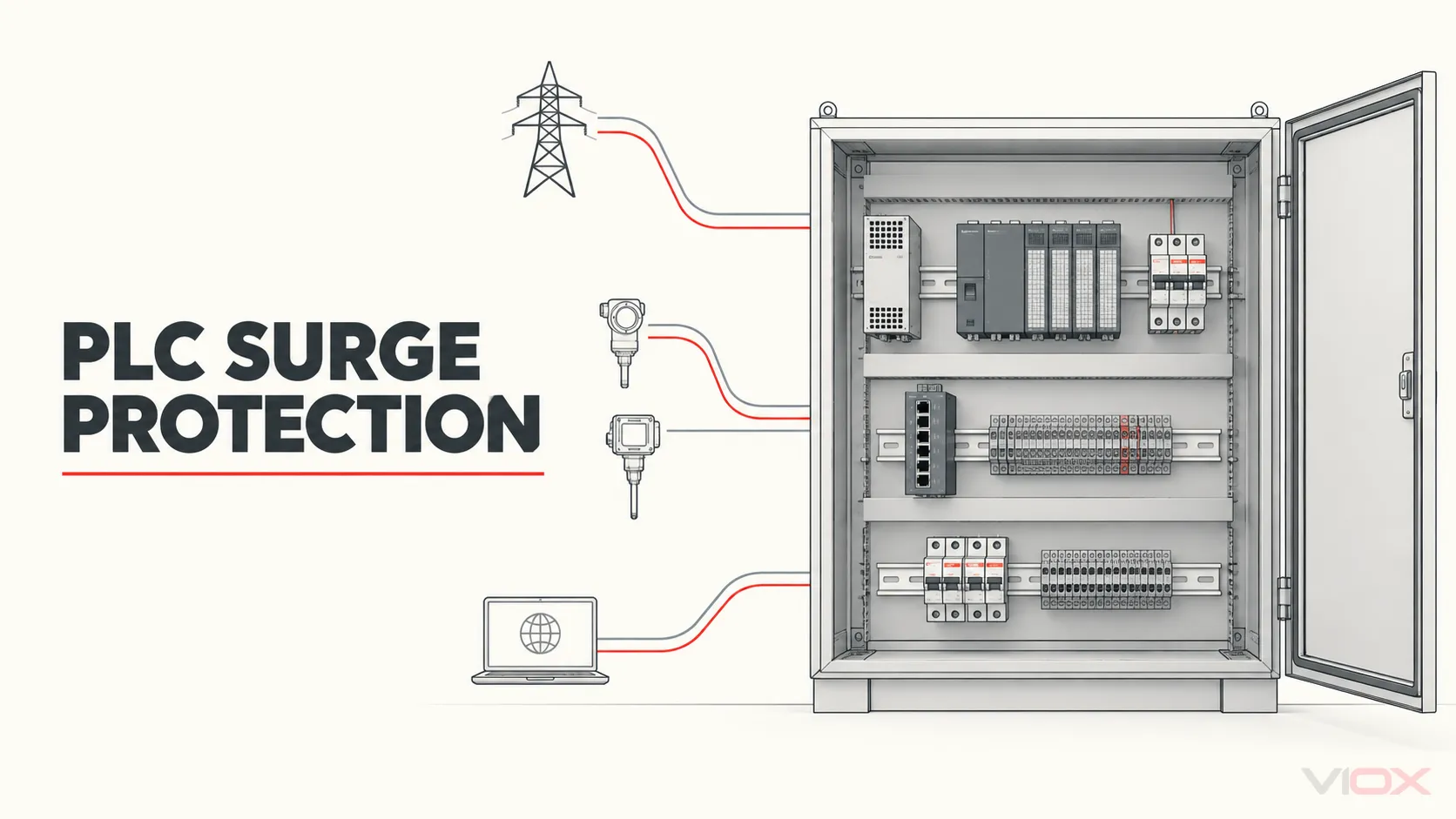
PLC surge protection starts by identifying every conductive path that crosses the control-cabinet or protection-zone boundary: incoming AC, 24 VDC power, digital and analog I/O, copper communications, cable shields, antennas and protective earth. A power surge protective device (SPD) at the cabinet incomer limits transients on that power path; it does not automatically protect field wiring or communication ports.
The correct result is not a universal three-device package. It is a port-by-port design in which each protector is compatible with normal operation, limits the relevant surge modes to a level coordinated with the equipment, has a credible discharge path, and can be inspected and documented after installation.
Key Takeaways
- Draw the PLC boundary before selecting an SPD. Include power, field I/O, copper networks, shields, external antennas and every remote earth reference.
- Separate equipment immunity from SPD performance. IEC 61000-4-5 defines a repeatable surge-immunity test method; an IEC 61643 product standard defines requirements for the applicable SPD family. One does not replace the other.
- Treat AC power, DC power and signal networks as different interfaces. They use different selection variables and can fall under different parts of the IEC 61643 series.
- Do not assign universal values to every PLC. Acceptable operating voltage, surge immunity, protection level, load current, bandwidth and grounding depend on the exact PLC, power supply, I/O module, network and project.
- Commission the complete path. A correct part number cannot compensate for an unprotected cable entry, an incompatible signal protector or an ineffective bonding route.
Start With the PLC Protection Boundary
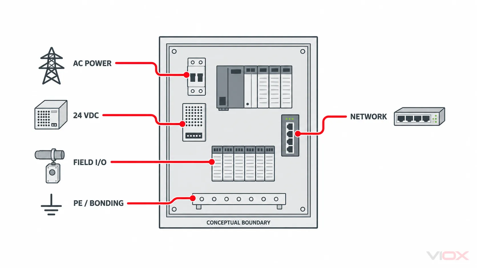
The PLC CPU is only one element inside the protected system. Its power supply, I/O modules, remote I/O, sensors, actuators, human-machine interface, industrial switch and communication gateways may connect to different electrical environments. A transient can therefore reach the control system without passing through the cabinet AC incomer.
Create a boundary drawing with the cabinet at the center. Add every cable that crosses the boundary and mark its remote endpoint. A cable to an outdoor transmitter, a second building, a motor-control center or a separately bonded machine deserves a different exposure review from a short internal patch lead.
For each path, ask four questions:
- What voltages, currents, frequencies and data signals occur during normal operation?
- Which differential-mode and common-mode surge paths are credible at this boundary?
- What immunity or withstand information is declared for the connected equipment and port?
- Where can diverted surge current return without creating a harmful voltage across another interface?
The boundary drawing is conceptual. It is not a terminal-level wiring diagram, and it cannot replace the exact equipment instructions or project electrical drawings.
PLC Port Protection Matrix
Use this matrix before requesting products. A row with missing inputs is an unresolved engineering decision, not permission to select a protector from nominal voltage alone.
| Boundary path | Inputs to collect | Normal-operation compatibility | Surge-performance evidence | Placement and verification |
|---|---|---|---|---|
| AC cabinet supply | Nominal and maximum continuous voltage, frequency, earthing arrangement, upstream SPDs, available fault current, upstream protective device | Uc/MCOV, protection modes, frequency, leakage or follow-current behavior where relevant | Applicable SPD Type/test class, Up and discharge-current declarations on the same test basis, short-circuit and backup-protection instructions | At the defined power-entry node with connection and bonding geometry checked against the manufacturer and installation rules |
| 24 VDC power bus | Full operating-voltage range, polarity, grounded or floating topology, source current, load current, external branches | Uc, polarity, continuous current for series paths, leakage, voltage drop and fault behavior | Declared voltage limitation and surge-current duty for the actual DC product and source conditions | At the boundary being protected; confirm normal bus voltage, polarity, reference-to-PE behavior and load operation |
| Discrete field I/O | Input/output type, nominal and maximum voltage, channel current, common/reference conductor, safety function | Uc, continuous current, series resistance, leakage and channel compatibility | Declared limiting performance by mode and test condition; equipment-port immunity evidence | At the exposed cable boundary, with every conductor and reference path accounted for; function-test the channel afterward |
| 4–20 mA or HART loop | Loop supply, maximum signal current, transmitter/load voltage budget, grounding, accuracy and HART requirement | Series resistance, leakage, voltage drop, capacitance and protocol compatibility | Differential/common-mode limiting data under declared tests | At the selected field and cabinet boundaries; verify loop current, available voltage and communication after installation |
| RS-485 or fieldbus | Signal standard, conductor count, maximum differential/common-mode voltage, topology, baud rate, cable and shield | Uc, pair balance, capacitance, bandwidth, series resistance and grounding | Signal-SPD test data applicable to the port and modes | At the protection-zone crossing; verify polarity, termination, biasing and communications |
| Industrial Ethernet or PoE | Ethernet category and speed, shield, connector, PoE type and power, link topology, building/zone crossing | Data rate, insertion loss, return loss, PoE voltage/current and shield continuity strategy | Applicable network-SPD limiting and transmission data | At the defined entry boundary; verify negotiated speed, PoE operation where used and shield/bonding arrangement |
| Coaxial antenna feed | Connector, frequency band, impedance, transmit power and antenna grounding | Frequency range, insertion loss, standing-wave performance and connector fit | Coaxial protector impulse data on a stated test basis | At the antenna-cable entry and bonding boundary; verify RF operation with suitable methods |
| Shield, PE and bonding path | Cabinet bonding, remote earths, cable shield terminations, parallel metallic paths | Continuous protective and functional requirements | Project bonding and lightning/EMC design evidence | Inspect the complete diverted-current path and record the as-built arrangement |
This matrix deliberately avoids default kA, clamping-voltage and conductor-size values. Those numbers become meaningful only after the circuit, exposure, test basis, equipment immunity and applicable installation framework are known.
Step 1: Confirm That the Disturbance Is a Surge
Not every PLC reset or communication error is caused by the unidirectional surge phenomenon addressed by IEC 61000-4-5. Contactors, variable frequency drives and other switching equipment can also produce electrical fast transients, repetitive ringing, conducted radio-frequency noise, voltage dips, interruptions or common-mode current. A sustained abnormal voltage is another condition again.
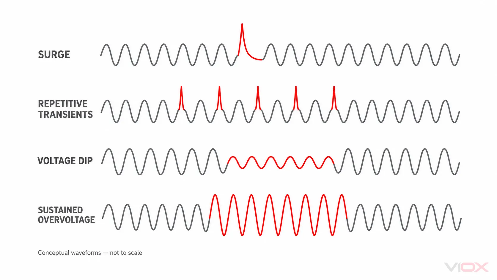
The distinction changes the corrective action:
| Evidence or symptom | Engineering direction |
|---|---|
| Event correlated with lightning exposure or a defined switching surge entering through a cable | Review IEC 61000-4-5 test evidence and the complete surge path |
| Repetitive error synchronized with contactor or solenoid operation | Investigate suppression at the coil/load, wiring separation and the applicable transient-immunity phenomenon |
| Communication errors synchronized with VFD operation | Review cable routing, shield termination, bonding, common-mode current and drive EMC instructions before prescribing another SPD |
| Long-duration overvoltage or neutral/ground fault condition | Treat it as a system abnormal-voltage or fault problem; an SPD is not a voltage regulator |
| Voltage dip or interruption during load starting | Investigate supply impedance, ride-through and power-quality behavior rather than expecting an SPD to maintain voltage |
IEC 61000-4-5 defines a common method for evaluating equipment against specified surge waveforms, coupling arrangements and test levels. It does not classify every disturbance in an industrial panel as a surge, and it does not represent a direct-lightning-current test.
Where the disturbance involves a drive, keep its input, pulse-width-modulated output, 24 VDC controls and signal interfaces separate. The VIOX VFD surge-protection guide owns that drive-specific review.
Step 2: Establish the Equipment Immunity Target
Do not infer a PLC port’s acceptable voltage from its nominal operating voltage. Obtain the exact PLC, power-supply, I/O, HMI, switch and gateway documentation. Look for the applied product standard, tested port, coupling mode, test level, source impedance, performance criterion and any required external protection.
IEC 61131-2:2017 covers functional and electromagnetic-compatibility requirements and related verification tests for PLCs, programmable automation controllers and associated peripherals. That scope makes it a useful starting point, but the project decision still depends on the exact product declaration. A CPU, a 24 VDC supply input, an analog channel and an Ethernet port should not be assigned one assumed withstand value.
Build an immunity register:
| Equipment ID | Exact port | Normal electrical limits | Declared surge test or immunity | Performance criterion | External protection required by manufacturer | Document revision |
|---|---|---|---|---|---|---|
| PLC-01 | CPU power input | |||||
| IO-01 | Digital input group | |||||
| AI-01 | Analog input channel | |||||
| NET-01 | Copper network port | |||||
| PSU-01 | AC input / DC output |
The SPD’s declared protection performance and the equipment’s immunity evidence must use compatible modes and test conditions before they can be coordinated. A low number printed under a different waveform or connection mode is not proof of protection.
Step 3: Decide the Required Protection Modes
A differential-mode transient appears between the active conductors of a circuit, such as L–N, DC+–DC− or the two wires of a balanced pair. A common-mode transient appears between one or more circuit conductors and a reference such as PE, cabinet metal or a remote earth.
The correct modes depend on the circuit topology and exposure. Protecting only the two active wires can leave a common-mode path unresolved. Connecting every circuit to PE through a protector can also be wrong when it disrupts isolation, creates leakage, conflicts with intrinsic-safety design or changes a deliberately floating system.
Record these decisions explicitly:
- which conductors belong to the normal circuit;
- whether the circuit is grounded, floating, isolated or capacitively referenced;
- where the remote equipment is bonded;
- which shields are bonded at one end, both ends or through a project-specific network;
- which differential and common-mode combinations the selected protector covers;
- whether the protector changes insulation monitoring, functional safety, measurement accuracy or communication quality.
This is why the cabinet PE bar is not simply a universal destination symbol. The design must show the complete high-frequency current path and the voltage that can develop between connected equipment during discharge.
Step 4: Specify the AC Cabinet-Supply SPD
An AC SPD at the control-cabinet supply can limit transients arriving on that supply and residual stress passed from upstream protection. Its selection begins with the actual power system, not with the PLC model.
Document:
- nominal voltage, highest continuous voltage, frequency and earthing arrangement;
- required protection modes;
- lightning and switching exposure at the cabinet node;
- upstream SPDs and the evidence for coordination between stages;
- acceptable voltage at the power supply and other connected equipment;
- available short-circuit current and the SPD’s declared fault-current suitability;
- required backup fuse, circuit breaker or internal disconnector conditions;
- connection length, routing, bonding and enclosure constraints.
IEC 61643-11:2025 applies to SPDs connected to AC low-voltage power circuits and is used with the common requirements in IEC 61643-01. Product-standard compliance is not the complete installation design: local wiring rules, project risk assessment, fault protection and manufacturer instructions still govern how the device is applied.
For the detailed multi-stage check, use the VIOX SPD coordination and cascading guide. For installation-code and safety boundaries, use the SPD installation requirements checklist.
Step 5: Treat the 24 VDC Bus as a Separate Power Interface
The 24 VDC supply may feed the PLC, remote I/O, sensors, relays and other loads. A transient can arrive from an external DC branch or appear through coupling between circuits. Before adding protection, determine whether the bus is grounded, floating or monitored for insulation resistance and whether the proposed device is connected in parallel or carries load current in series.
For a general DC power circuit, IEC 61643-41:2025 is the relevant IEC product-standard scope for SPDs connected to DC low-voltage power systems. It explicitly excludes photovoltaic applications, which remain under IEC 61643-31. Therefore, a PV-specific marking or standard reference should not be treated as automatic evidence for a PLC’s 24 VDC control bus.
Collect these DC inputs:
- minimum, nominal and maximum normal bus voltage, including charger or supply tolerance;
- polarity and any permitted reverse condition;
- grounded conductor, floating arrangement or insulation-monitoring method;
- source capability and prospective DC fault current;
- continuous load current if the selected device has series terminals;
- required differential and common-mode protection;
- declared protection level and test basis;
- failure behavior, disconnection, indication and replacement method;
- effect on safety-related outputs, redundancy and system availability.
Do not specify 30 V Uc, 50 V Up or a fixed kA rating for every 24 VDC system. Those may be plausible values for particular products or circuits, but only exact equipment and protector documentation can establish the project requirement.
Step 6: Protect Field I/O and Copper Communications by Interface
Field cables can cross the cabinet boundary after the AC supply has already been protected. An AC power SPD has no control over a transient arriving first at an analog input, RS-485 terminal or Ethernet connector.
IEC 61643-21:2025 covers SPDs connected to telecommunications and signalling networks, including networks that also carry power. IEC 61643-22:2015 addresses their selection, operation, location and coordination. The standards establish a framework; they do not make one generic signal protector suitable for every interface.
Discrete I/O
Identify whether the channel is an input or output, sinking or sourcing, its normal and maximum voltage, channel current, common conductor and safety function. A series protector must not introduce excessive voltage drop, leakage or current limitation. If the field circuit is safety-related, any added component requires review within that safety design.
4–20 mA and HART
Calculate the loop voltage budget after adding the protector’s series resistance at maximum loop current. Confirm leakage and capacitance against accuracy and communication requirements. Record grounding and shield treatment at the field device and cabinet; do not assume that a protector installed at one end resolves every zone boundary.
RS-485 and Other Fieldbuses
Match maximum working and common-mode voltage, conductor count, pair balance, data rate, capacitance, series resistance and topology. Verify termination and biasing after installation. A protector that survives a high impulse can still be unacceptable if it corrupts the normal signal.
Industrial Ethernet and PoE
Confirm Ethernet category and data rate, connector, shield strategy and whether the same cable supplies Power over Ethernet. Review transmission parameters as well as surge limitation. Where a copper link crosses buildings or protection zones, assess both ends and the bonding relationship. Fibre can remove a conductive data path, but powered equipment and metallic members still require their own review.
Antenna and Coaxial Paths
Remote PLCs and telemetry cabinets may have an external cellular, radio or GNSS antenna. Select a protector for connector, impedance, operating band and transmit power, then place it at the defined cable-entry and bonding boundary. A power SPD cannot protect a coaxial path.
The VIOX signal surge protector selection guide provides the deeper voltage, current, resistance, bandwidth and topology workflow. This PLC page owns the system boundary; the signal guide owns detailed interface-device selection.
Step 7: Make Placement, Bonding and Coordination Verifiable
An SPD diverts current through an installed loop. Connection inductance, conductor routing and bonding impedance can add voltage beyond the device’s declared protection level. However, a universal distance or conductor-size statement is not safe across all power and signal interfaces.
For every selected protector, mark on the drawing:
- the boundary and equipment it protects;
- the exposed and protected sides of any series signal device;
- the protected conductors and protection modes;
- the bonding or return point;
- the complete connection route and any parallel bypass path;
- upstream and downstream SPDs that require coordination evidence;
- the manufacturer-required overcurrent or backup protection;
- access for status inspection, isolation and replacement.
Where several SPD stages are used, voltage coordination, energy coordination, distance/decoupling and fault coordination are separate checks. Do not assume that Type 1, Type 2 and Type 3 labels prove a coordinated cascade.
Step 8: Commission the PLC Protection System
Commissioning confirms that the approved design was installed and that normal PLC operation was not degraded. It does not reproduce a standardized surge test and does not prove the remaining life of a protective component.
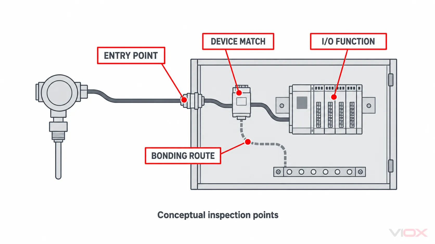
Use this evidence sequence:
- Document match: record installed manufacturer, model, module and document revision for every protection point.
- Boundary match: confirm every exposed cable in the port schedule reaches the intended protection point before the protected equipment.
- Electrical match: confirm voltage, polarity, grounding/reference condition, protective device and conductor arrangement against the approved design.
- Status match: check local indicators and remote contacts using the exact model truth table; green, red, NO and NC are not universal meanings.
- Functional match: verify PLC power, I/O states, analog accuracy, fieldbus communication, Ethernet speed and PoE function where applicable.
- As-built record: photograph and document routes, shield terminations, bonding points, labels and replaceable-module identities.
- Maintenance handoff: define the approved inspection triggers, replacement evidence and responsible role using product and site procedures.
If an SPD’s dry contact will report to the PLC or building-management system, follow the separate SPD remote-signaling guide. Remote monitoring reports a documented contact state; it does not verify every protected interface or measure remaining surge capacity.
Copy-Ready PLC Surge-Protection RFQ Worksheet
Send this information with the single-line diagram and cabinet drawings:
PROJECT AND MARKET
Site / machine:
Destination country and applicable rules:
Indoor / outdoor / hazardous-area conditions:
Lightning protection zone or exposure information:

AC POWER ENTRY
Nominal and maximum continuous voltage:
Frequency and earthing arrangement:
Available short-circuit current:
Upstream protective device:
Existing upstream/downstream SPD models:
Required protection modes and equipment immunity objective:

24 VDC POWER
Minimum / nominal / maximum voltage:
Grounded, floating or insulation-monitored:
Source and prospective fault-current information:
Continuous load current through any series device:
External DC branches and remote endpoints:

PLC AND FIELD PORT SCHEDULE
PLC / I/O / HMI / switch model and document revision:
Each port type and normal electrical limits:
Cable length, route, indoor/outdoor and inter-building exposure:
Remote equipment and bonding reference:
Shield arrangement:
Required data rate, accuracy, HART or PoE support:
Declared equipment surge-immunity evidence:

INSTALLATION AND EVIDENCE
Available DIN-rail space and enclosure constraints:
Proposed protector location and bonding point:
Required backup protection or disconnection:
Local status / remote contact requirement:
Required product standard, test report, declaration or certificate:
Replacement-module and maintenance requirements:
Final Engineering Rule
A PLC control system is not protected merely because an SPD appears on the cabinet bill of materials. Protection is complete only when every relevant conductive boundary has a documented decision, each device is compatible with normal operation, the declared limiting performance is coordinated with the exact equipment and test mode, and the installed discharge path is verified.
After completing the worksheet, review the VIOX SPD product family and the VIOX industrial automation application. For model-level documentation, send the port schedule, electrical system data, cabinet drawings, target market and required evidence to [email protected]. A family page or general article is not evidence that a particular model fits the project.
Sources
- IEC 61131-2:2017 — Programmable controllers: equipment requirements and tests
- IEC 61000-4-5:2014 — Surge immunity test methods
- IEC 61643-11:2025 — SPDs connected to AC low-voltage power systems
- IEC 61643-41:2025 — SPDs connected to DC low-voltage power systems
- IEC 61643-21:2025 — SPDs connected to telecommunications and signalling networks
- IEC 61643-22:2015 — Selection and application of signalling-network SPDs
This article is a system-design framework, not a construction drawing or approval for a particular PLC, SPD or installation. Follow the exact equipment instructions, project risk assessment, functional-safety requirements and electrical rules applicable to the site. Work inside industrial control equipment should be performed only by qualified personnel under an approved safe-work procedure.