
Why Most Engineers Confuse Protection Devices—And Pay the Price
Last month, an automation engineer replaced a failed PLC output module for the third time in six months. The culprit? Missing freewheeling diodes on relay coils. Cost: $850 in parts plus 12 hours of downtime. The ironic part? The facility had just installed $15,000 worth of surge protection devices to guard against lightning strikes.
This scenario reveals a critical misunderstanding: freewheeling diodes and surge arresters are not alternatives—they protect against completely different threats at entirely different scales. Confusing them, or assuming one replaces the other, leaves gaps in your protection strategy that eventually cause expensive failures.
This guide provides the technical clarity to specify the right protection device for every situation, eliminate costly mistakes, and understand why properly designed systems require both technologies working together.
Understanding Freewheeling Diodes (Flyback/Snubber Diodes)
What Is a Freewheeling Diode?
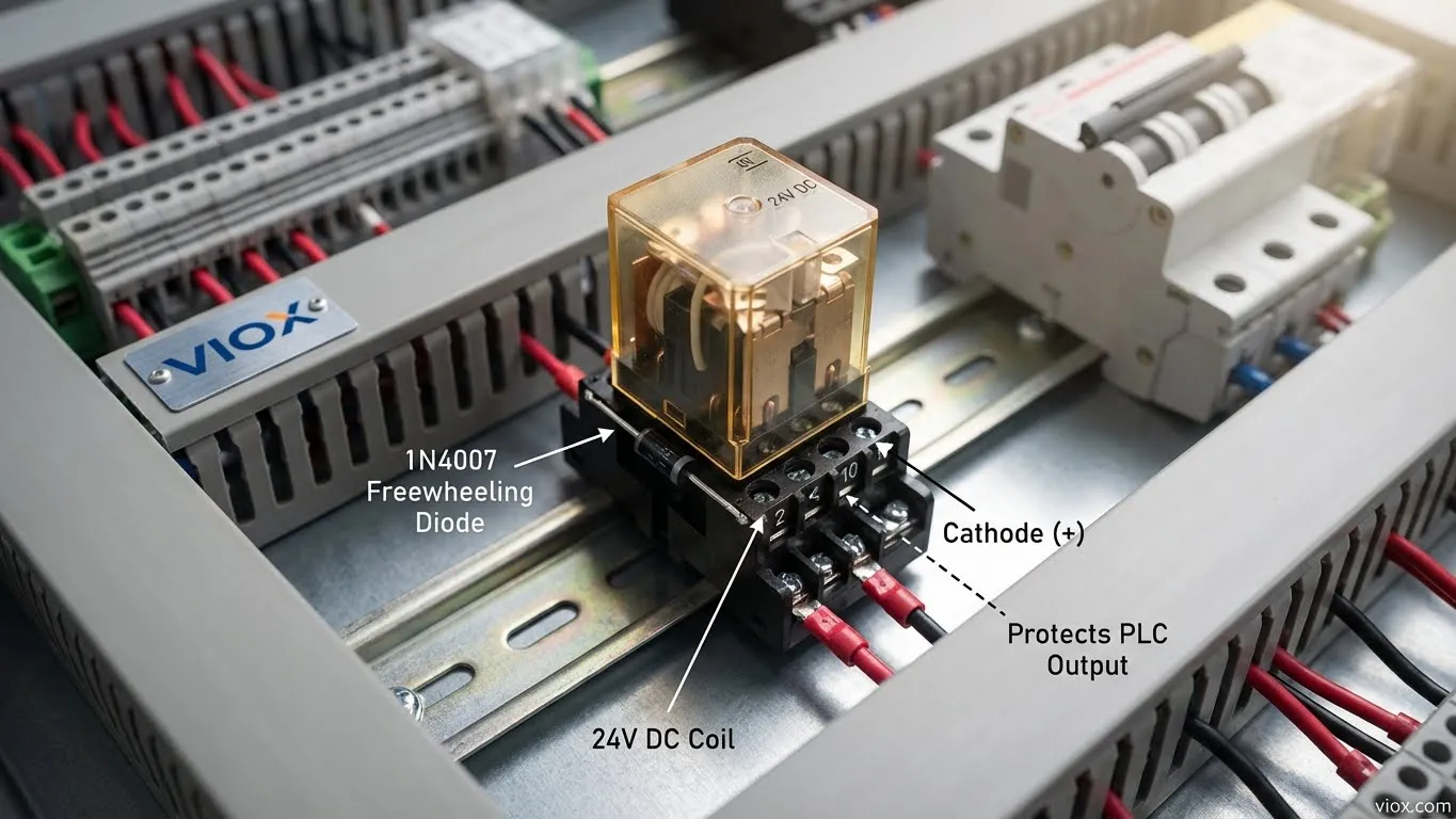
A freewheeling diode—also called flyback, snubber, suppressor, catch, clamp, or commutating diode—is a semiconductor device connected across inductive loads to suppress voltage spikes generated during switching. The primary purpose: protect switches (transistors, MOSFETs, IGBTs, relay contacts, PLC outputs) from destructive back-EMF (electromotive force) produced when current through an inductor suddenly changes.
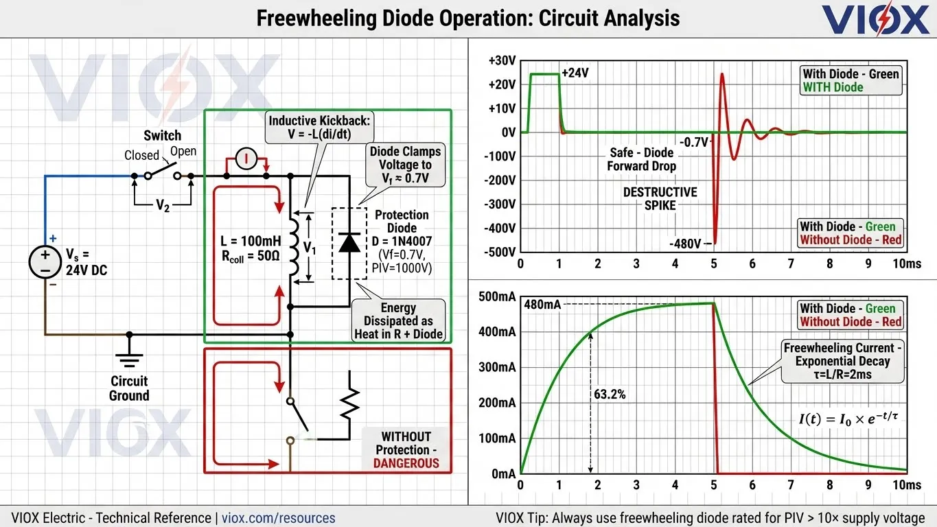
The voltage spike problem: When current through an inductor (relay coil, solenoid, motor winding) is interrupted, Lenz’s law dictates that the magnetic field collapses and induces a voltage spike attempting to maintain current flow. This spike follows the equation V = -L(di/dt), where L is inductance and di/dt represents the rate of current change. With typical switching speeds, this voltage can reach 10× the supply voltage or higher—turning a 24V circuit into a 300V+ hazard that destroys semiconductor switches instantly.
How Freewheeling Diodes Work
The freewheeling diode connects in parallel with the inductive load, reverse polarity to the supply. This simple placement creates a protection mechanism:
During normal operation: The diode is reverse-biased (anode more negative than cathode), so it presents high impedance and does not conduct. Current flows normally through the inductive load from the supply through the closed switch.
When the switch opens: The inductor attempts to maintain current flow, but with the switch open, there’s no path through the supply. The inductor voltage polarity reverses (the end that was positive becomes negative), which forward-biases the freewheeling diode. The diode begins conducting immediately, providing a closed loop: inductor → diode → back to inductor.
Energy dissipation: The magnetic energy stored in the inductor (E = ½LI²) dissipates as heat in the inductor’s DC resistance and the diode’s forward drop. Current decays exponentially with time constant τ = L/R, where R is the total loop resistance. The voltage across the switch is clamped to approximately supply voltage + diode forward drop (0.7-1.5V)—safe for all standard switches.
Technical Specifications
- Response time: Nanoseconds (typically <50ns for standard silicon, <10ns for Schottky)
- Voltage handling: Typically <100V DC circuits (though PIV ratings can be 400V-1000V)
- Current handling: Continuous ratings from 1A to 50A+; transient surge ratings 20A-200A (for 8.3ms half-sine wave)
- Forward voltage drop: 0.7-1.5V (silicon PN junction), 0.15-0.45V (Schottky barrier)
- Common types:
- Standard silicon (1N4001-1N4007 series): General-purpose, PIV ratings 50V-1000V, 1A continuous
- Schottky diodes: Fast recovery (<10ns), low forward drop (0.2V), preferred for PWM circuits >10kHz
- Fast recovery diodes: Optimized for hard-switching applications, recovery times <100ns
Typical applications: Relay coil drivers, solenoid valve control, DC motor PWM drives, automotive fuel injectors, contactor circuits, HVAC actuators, Arduino/microcontroller I/O modules.
Selection Criteria
- Peak forward current capacity: Must handle the inductor’s stored energy discharge. Calculate peak transient current as approximately I_peak ≈ V_supply / R_coil, then select diode rated for 2-3× this value to provide safety margin.
- Reverse breakdown voltage (PIV): Must exceed the maximum voltage that could appear across the diode. Conservative practice: PIV ≥ 10× supply voltage. For 24V circuits, use ≥400V rated diode (1N4004 or higher).
- Forward voltage drop: Lower is better to minimize power dissipation during freewheeling. Schottky diodes (Vf ≈ 0.2V) dissipate 1/3 the power of standard silicon (Vf ≈ 0.7V) for equivalent current.
- Recovery time: For high-frequency switching (PWM >10kHz), use Schottky or fast-recovery diodes. Standard rectifier diodes may have recovery times >1μs, causing switching losses in fast circuits.
Understanding Surge Arresters (SPD/MOV/GDT)
What Is a Surge Arrester?
A surge arrester—formally called a Surge Protection Device (SPD) or Transient Voltage Surge Suppressor (TVSS)—protects entire electrical systems from external high-energy transients. Unlike the component-level protection of freewheeling diodes, surge arresters defend against system-level threats that enter through power distribution lines.
Primary sources of external surges:
- Lightning strikes: Direct hits to overhead lines or nearby ground strikes coupling into wiring (impulse currents 20kA-200kA)
- Grid switching operations: Utility capacitor bank switching, transformer energization, fault clearing (transients 2kV-6kV)
- Motor starting: Large motor inrush currents creating voltage sags and recovery transients
- Capacitor bank operations: Switching power factor correction capacitors generates high-frequency transients
How Surge Arresters Work
Surge arresters employ voltage-clamping components that transition from high impedance to low impedance when voltage exceeds a threshold, creating a path to ground that diverts surge current away from protected equipment.
Metal Oxide Varistor (MOV) mechanism: The MOV consists of zinc oxide ceramic pressed into a disc or block between two metal electrodes. At normal operating voltage, the MOV exhibits extremely high resistance (>1MΩ) and draws only microamps of leakage current. When voltage rises to the varistor voltage (Vn), grain boundaries between ZnO crystals break down, resistance drops to <1Ω, and the MOV conducts surge current to ground. After the transient passes, the MOV automatically returns to high-impedance state.
Gas Discharge Tube (GDT) mechanism: A GDT contains two or three electrodes separated by small gaps (<0.1mm) inside a sealed ceramic or glass tube filled with inert gas (argon, neon, or mixtures). At normal voltage, the gas is non-conductive and the GDT presents open-circuit impedance. When applied voltage reaches the spark-over voltage (Vs), the gas ionizes (creating a plasma), impedance drops dramatically, and the GDT conducts surge current through the ionized gas path. After current falls below the holding current threshold, the gas de-ionizes and the GDT returns to its insulating state.
Clamping voltage: The voltage that appears across protected equipment during a surge event is called the “let-through voltage” or “voltage protection rating” (Vr). Lower Vr values provide better protection. SPDs are characterized by the voltage they clamp to at specific surge current levels (typically tested at 5kA or 10kA, 8/20μs waveform).
Technical Specifications
- Response time:
- MOV: <25 nanoseconds (component level). Note: While the component responds instantly, installation lead length adds inductance that significantly affects system response time and let-through voltage. Proper low-impedance installation is critical.
- GDT: 100 nanoseconds to 1 microsecond (slower due to gas ionization delay)
- Hybrid (MOV+GDT): <25ns initial response (MOV), sustained conduction via GDT
- Voltage handling: 120V AC to 1000V DC systems (continuous operating voltage Un)
- Current handling: Nominal discharge current (In) 5kA-20kA, maximum discharge current (Imax) 20kA-100kA (8/20μs waveform per IEC 61643-11)
- Energy absorption: MOVs rated in joules (J); typical panel SPDs: 200J-1000J per phase
- Classification (UL 1449 / IEC 61643-11):
- Type 1 (Class I): Service entrance, tested with 10/350μs waveform (simulates direct lightning), 25kA-100kA rating
- Type 2 (Class II): Distribution panels, tested with 8/20μs waveform (indirect lightning/switching transients), 5kA-40kA rating
- Type 3 (Class III): Point-of-use near sensitive loads, 3kA-10kA rating
- Standards compliance: UL 1449 Ed.4 (North America), IEC 61643-11 (International), IEEE C62.41 (surge environment characterization)
MOV vs GDT Technology Comparison
| Feature | Metal Oxide Varistor (MOV) | Gas Discharge Tube (GDT) | Hybrid (MOV+GDT) |
|---|---|---|---|
| Response Time | <25ns (very fast) | 100ns-1μs (slower) | <25ns (MOV dominates initial response) |
| Clamping Voltage | Moderate (1.5-2.5× Un) | Low (1.3-1.8× Un) after ionization | Low overall due to coordinated action |
| Current Capacity | High (20kA-100kA for short pulses) | Very high (40kA-100kA sustained) | Highest (MOV handles fast edge, GDT handles energy) |
| Energy Absorption | Limited by thermal mass, degrades over time | Excellent, virtually unlimited for rated current | Excellent, MOV protected by GDT |
| Leakage Current | 10-100μA (increases with age) | <1pA (essentially zero) | <10μA (GDT isolates MOV at normal voltage) |
| Capacitance | High (500pF-5000pF) | Very low (<2pF) | Low (GDT in series reduces effective capacitance) |
| Failure Mode | Can short or open; requires thermal disconnect | Typically shorts (spark-over voltage decreases) | MOV thermal disconnect prevents fire hazard |
| Lifespan | Degrades with surge count and overvoltage stress | Virtually unlimited (rated for 1000+ operations) | Extended (GDT reduces MOV stress) |
| Cost | Low ($5-$20) | Moderate ($10-$30) | Higher ($25-$75) |
| Best Applications | General AC/DC circuits, renewable energy, industrial panels | Telecom, data lines, precision equipment (low capacitance critical) | Critical applications requiring maximum protection and longevity |
Side-by-Side Comparison: Freewheeling Diode vs Surge Arrester
| Feature | Freewheeling Diode | Surge Arrester (SPD) |
|---|---|---|
| Primary Purpose | Suppress inductive kickback from local loads | Protect systems from external high-energy surges |
| Surge Origin | Self-induced (circuit’s own inductive load) | External (lightning, grid transients) |
| Protection Scale | Component-level (single switch/transistor) | System-level (entire electrical panel) |
| Voltage Range | <100V typically | Hundreds to thousands of volts |
| Current Capacity | Amps (transient: 20A-200A) | Kiloamps (5kA-40kA+) |
| Response Time | Nanoseconds (<50ns) | Nanoseconds (MOV) to microseconds (GDT) |
| Technology | Simple PN junction or Schottky diode | MOV, GDT, or hybrid ceramic-based components |
| Energy Handling | Millijoules to joules | Hundreds to thousands of joules |
| Connection | Parallel across inductive load | Parallel across power lines (line-to-ground, line-to-line) |
| Degradation | Minimal (unless exceeded PIV rating) | MOV degrades with repeated surges; GDT long-life |
| Cost | $0.05-$2 per component | $15-$200+ per SPD device |
| Standards | General diode specs (JEDEC, MIL-STD) | UL 1449, IEC 61643, IEEE C62.41 |
| Typical Applications | Relay drivers, motor controls, solenoids | Service entrances, distribution panels, sensitive equipment |
| Installation Location | Directly at inductive load terminals | Main service, distribution panels, sub-panels |
| Failure Consequences | Damaged switch/PLC output ($50-$500) | Destroyed equipment/entire system ($1000s-$100,000s) |
| Required Quantity | One per inductive load (could be 100s per facility) | 3-12 per facility (coordinated cascade) |
When to Use Each Protection Device
Freewheeling Diode Applications
Component-level protection scenarios:
- PLC output modules: When sinking/sourcing current to drive relay coils, contactors, or solenoid valves. Protects transistor outputs from 300V+ spikes that destroy output circuitry.
- Contactor control circuits: DC coils in motor starters, HVAC contactors, industrial machinery. When designing control panels with contactors, proper surge suppression prevents output card failures—learn more about contactor selection and protection.
- DC motor PWM drives: H-bridge circuits switching inductive motor windings at kilohertz frequencies. Schottky diodes preferred for low Vf and fast recovery.
- Automotive systems: Fuel injector drivers, ignition coil drivers, cooling fan control, power window motors—any 12V/24V inductive load.
- Arduino/microcontroller relay modules: Protects GPIO pins (typically rated for only ±0.5V beyond supply rails) when driving relay coils.
- HVAC controls: Zone damper actuators, reversing valves, compressor contactors in residential/commercial climate control.
For additional guidance on coil protection failures, review contactor troubleshooting and protection strategies.
Surge Arrester Applications
System-level protection scenarios:
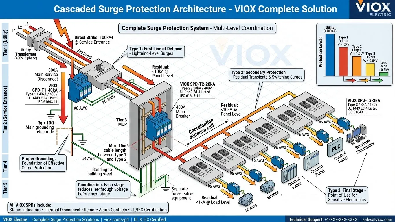
- Main electrical service entrance (Type 1 SPD): First line of defense against direct/nearby lightning strikes. Handles 40kA-100kA impulse currents. Understanding proper SPD installation locations in electrical panels ensures effective protection.
- Distribution panelboards and subpanels (Type 2 SPD): Secondary protection against residual surges passing through Type 1 devices plus locally generated switching transients. Follow SPD installation requirements and code compliance for NEC/IEC conformance.
- Solar PV systems: Combiner box SPDs protect inverters from lightning-induced surges in exposed rooftop/ground-mount installations. Specialized guidance available in our solar system SPD selection guide.
- Industrial motor control centers (MCCs): Protects VFDs, soft starters, and control equipment from grid transients and large motor switching.
- Data centers: Critical equipment protection requiring coordinated SPD cascade (Type 1 + Type 2 + Type 3) with low let-through voltage.
- Telecommunications equipment: Low-capacitance GDT-based SPDs on sensitive data lines to prevent signal distortion.
For comprehensive SPD specification guidance, see the ultimate SPD buying guide for distributors and understand surge protection device fundamentals.
Common Mistakes and Misconceptions
Mistake 1: Using Freewheeling Diode for Lightning Protection
The error: Specifying a freewheeling diode (1N4007, rated for 1A continuous, 30A surge) at the service entrance to protect against lightning strikes.
Why it fails: Lightning impulse currents reach 20kA-200kA with rise times <10μs. A standard diode rated for 30A (8.3ms duration) vaporizes instantly when exposed to kiloamp currents. The diode fails in short-circuit mode, creating a direct fault to ground that trips the main breaker or causes fire.
Correct approach: Always use UL 1449-listed SPDs rated for external transients. Type 1 SPDs at service entrance must handle 10/350μs waveforms (simulating direct lightning) with ratings 25kA-100kA.
Mistake 2: Omitting Freewheeling Diodes on Relay Coils
The rationalization: “This relay has been working fine for three years without a freewheeling diode, so we don’t need one.”
Hidden reality: The relay works until the PLC output fails. Inductive kickback spikes of 300V-500V gradually stress the output transistor’s junction, causing parametric degradation. After hundreds of switching cycles, the transistor fails (often appearing as “locked-on” or “unable to switch” condition). Replacing the PLC output module costs $200-$500 plus troubleshooting time and system downtime.
By the numbers: 1N4007 diode costs $0.10. PLC output module costs $250. Failure prevention ROI: 2500:1.
Additional guidance on preventing coil-related failures: contactor troubleshooting guide.
Mistake 3: Wrong SPD Type Selection
Scenario A—Type 3 at service entrance: Installing a 3kA-rated point-of-use SPD at the main panel, assuming “any surge protector will work.”
Why it fails: Type 3 SPDs are designed for residual transients after upstream protection has already clamped the bulk of surge energy. A 3kA device exposed to a 40kA lightning surge operates outside its design envelope, fails immediately (often in short-circuit mode), and provides no protection.
Scenario B—No coordination: Installing Type 1 and Type 2 SPDs with insufficient cable length between stages (e.g., 2 meters instead of required 10+ meters). Both SPDs attempt to operate simultaneously, causing uncontrolled current sharing and potential failure of the faster-responding device.
Correct approach: Follow SPD deployment triage matrix strategies and use proper SPD kA rating sizing guidelines. Avoid common errors by implementing SPD installation best practices.
Mistake 4: Ignoring SPD Degradation
The assumption: “We installed SPDs five years ago, so we’re protected.”
Reality: MOV-based SPDs degrade with each surge event. Every time the MOV clamps a voltage spike, microstructural changes occur in the zinc oxide ceramic. After 10-50 significant surge events (depending on energy level), the MOV’s clamping voltage increases and its energy absorption capacity decreases. Eventually, the MOV fails—either short-circuit (causing nuisance breaker trips) or open-circuit (providing no protection).
Warning signs:
- Increased leakage current (measurable with clamp meter: normal <0.5mA, degraded >5mA)
- Status indicator LED changes from green to yellow or red
- Physical evidence: casing cracks, burn marks, buzzing sounds, heat during normal operation
Maintenance schedule: Inspect Type 2 SPDs annually in lightning-prone regions, every 2-3 years in moderate areas. Replace MOV-based SPDs after major surge events (confirmed lightning strikes, nearby utility faults). Learn about SPD lifespan and MOV aging mechanisms to plan replacement cycles.
Complementary Protection Strategy: Why You Need Both
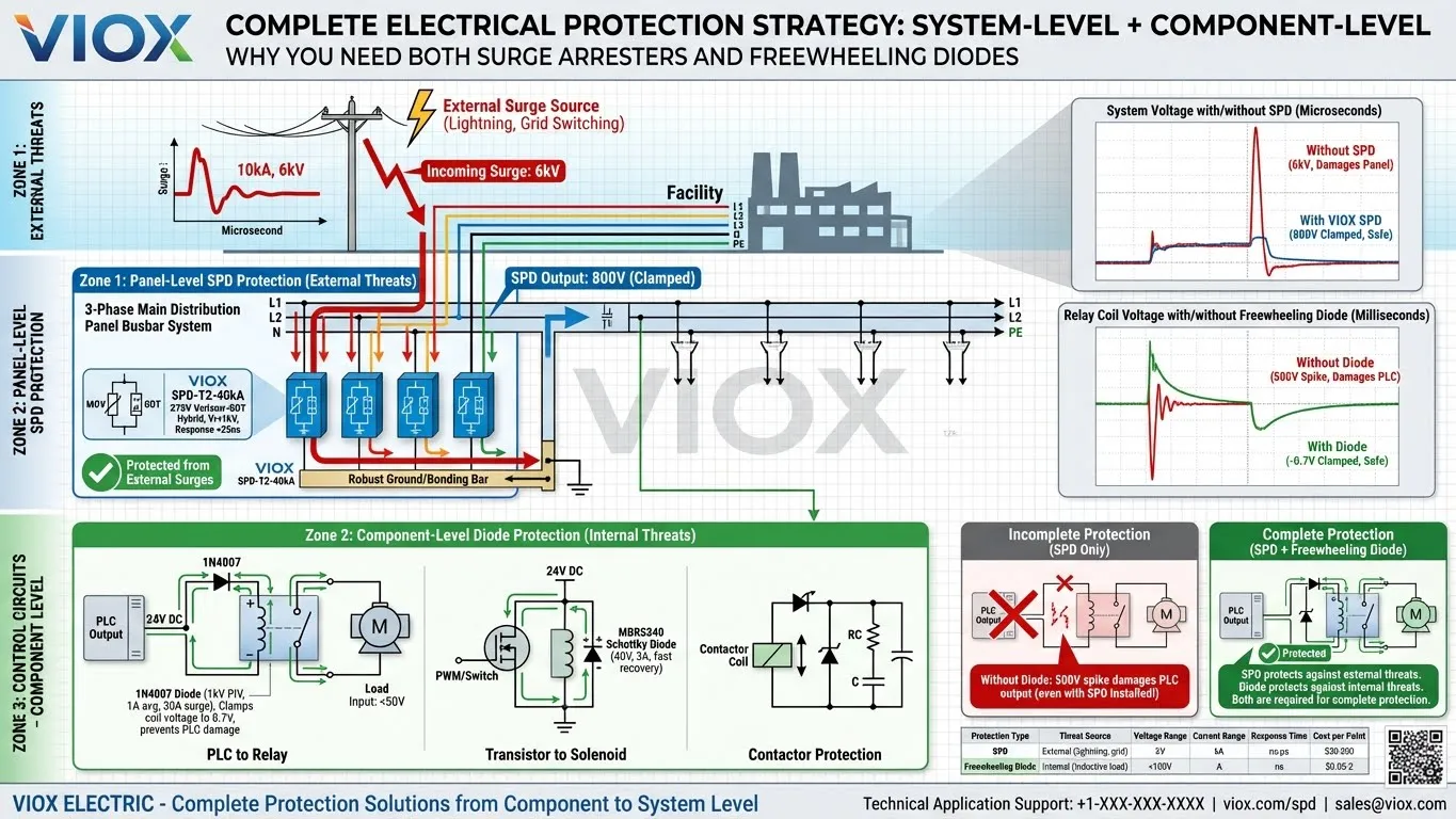
The fundamental principle: Freewheeling diodes and surge arresters are not alternatives—they protect against different threats at different scales and must work together in properly designed systems.
The Protection Gap
Without freewheeling diodes: Your facility has $20,000 worth of Type 1 and Type 2 SPDs protecting against external surges. When a PLC output switches off a 24V relay coil, the 400V inductive spike destroys the PLC output transistor. The SPDs do nothing—they’re designed for kilovolt, kiloamp grid-level transients, not for localized component-level spikes. Cost: $350 PLC module + 4 hours downtime.
Without SPDs: Every relay coil has a freewheeling diode, perfectly protecting PLC outputs from inductive kickback. A lightning strike 200 meters away induces a 4kV surge on the facility’s service entrance. The diodes, rated for <100V, vaporize along with the power supplies, PLCs, VFDs, and control electronics connected to the unprotected panel. Cost: $50,000+ equipment replacement + weeks of downtime.
Complete Protection Example: Industrial Control Panel
A properly protected industrial control panel with motor starters, PLC, and HMI includes:
System-level protection (surge arresters):
- Type 2 SPD (40kA, 275V) at main panel incoming feeders, connected line-to-ground on each phase
- Proper grounding with ground bar bonded to building structural steel
- Adequate conductor sizing (#6 AWG minimum for SPD ground connections)
Component-level protection (freewheeling diodes):
- 1N4007 diodes across every relay coil controlled by PLC outputs
- Fast-recovery diodes (or Schottky) across solenoid valve coils in high-cycle-rate applications
- RC snubbers or MOV suppressors on AC contactor coils (alternatively, bidirectional TVS diodes for AC applications)
This dual-layer approach addresses both threat categories. For comprehensive electrical protection architecture, understand the relationships between grounding, GFCI, and surge protection. Compare related protection technologies: MOV vs GDT vs TVS components and clarify surge arrester vs lightning arrester terminology.
Selection Guide for Engineers
Quick Decision Matrix
Choose Freewheeling Diode when:
- Protecting transistors, relays, IGBTs, or mechanical switches from inductive kickback
- Load is a relay coil, solenoid, motor winding, or transformer primary
- Voltage spike originates from circuit’s own switching action (self-induced)
- Operating voltage <100V DC
- Budget allows $0.05-$2 per protection point
- Application requires hundreds of protection points (one per inductive load)
Choose Surge Arrester when:
- Protecting against external surges (lightning, utility switching, motor starting transients)
- Protecting entire electrical panels, equipment rooms, or systems
- Operating voltage >50V AC or >100V DC
- Surge energy exceeds 100 joules
- Compliance with UL 1449, IEC 61643, or NEC Article 285 required
- Application requires 1-12 devices per facility (coordinated cascade)
VIOX Product Recommendations
VIOX Electric offers complete surge protection solutions for industrial, commercial, and renewable energy applications:
SPD Product Portfolio:
- Type 1 (Class I) SPDs: Service entrance protection, 10/350μs waveform tested, 40kA-100kA ratings, suitable for direct lightning exposure
- Type 2 (Class II) SPDs: Distribution panel protection, 8/20μs waveform tested, 5kA-40kA ratings, modular DIN-rail or panel-mount configurations
- Type 3 (Class III) SPDs: Point-of-use protection near sensitive equipment, 3kA-10kA ratings, plug-in formats available
- Hybrid MOV+GDT technology: Extended lifespan, superior energy handling, low let-through voltage, reduced degradation compared to MOV-only designs
Voltage Ranges: 120V-1000V AC/DC systems
Certifications: UL 1449 Ed.4, IEC 61643-11, CE marked, suitable for NEC-compliant installations
Features:
- Visual status indicators (green = operational, red = replace)
- Thermal disconnect prevents fire hazard if MOV overheats
- Remote alarm contacts for integration with building monitoring systems
- IP20-IP65 enclosure ratings depending on application
Browse the complete VIOX SPD product catalog for technical specifications and application guides. For strategic deployment planning, review the SPD deployment triage matrix and SPD kA rating sizing methodology.
Frequently Asked Questions
Q: Can I use a freewheeling diode instead of a surge arrester to save money?
A: Absolutely not. Freewheeling diodes are rated for amps at low voltage (<100V) and cannot survive kiloamp lightning currents or kilovolt grid transients. A 1N4007 diode rated for 30A surge current (8.3ms duration) vaporizes instantly when exposed to a 20kA lightning impulse (<10μs rise time). Using a $0.50 diode where a $50 SPD is required results in catastrophic failure, potential fire hazard, and zero protection for downstream equipment. The 100:1 cost difference reflects entirely different protection scales and capabilities.
Q: Do I need both freewheeling diodes AND surge arresters in my control panel?
A: Yes, in virtually all industrial and commercial applications. They serve complementary, non-overlapping functions:
- Freewheeling diodes protect individual components (PLC outputs, transistors, IGBTs) from localized inductive kickback (self-generated, <100V, amps) when switching relay coils or motor windings
- Surge arresters protect the entire panel from external transients (lightning, grid switching, kV, kA) entering through power distribution lines
Even with perfect SPD protection against external surges, omitting freewheeling diodes leaves your PLC outputs vulnerable to 300V+ spikes from relay coils. Conversely, even with diodes on every relay, omitting SPDs leaves the entire panel vulnerable to lightning-induced surges that destroy power supplies, drives, and control electronics.
Q: What happens if I omit the freewheeling diode on a relay coil?
A: When the relay coil is de-energized, the collapsing magnetic field generates back-EMF following V = -L(di/dt). For a typical 24V relay with 100mH inductance and 480mA steady current, opening the switch in 10μs produces a -480V spike. This spike:
- Destroys semiconductor switches (transistors, MOSFETs, IGBTs exceed breakdown voltage, causing junction failure)
- Damages PLC output cards (replacement cost $200-$500)
- Causes arcing at mechanical contacts (accelerated wear, contact welding)
- Generates electromagnetic interference (EMI) affecting nearby circuits and communications
The diode costs $0.10 and prevents all these failures. Replacement cost of a PLC output module: $250+ plus troubleshooting time and system downtime. Return on investment: 2500:1.
Q: How do I know if my surge arrester has degraded and needs replacement?
A: MOV-based SPDs degrade progressively with each surge event. Monitoring methods:
Visual indicators: Most quality SPDs include LED status lights. Green = operational, yellow = reduced capacity, red = failed/replace immediately. Check indicator status quarterly.
Electrical testing: Measure leakage current with clamp meter on SPD’s ground conductor. Normal: <0.5mA. Degraded: 5-20mA. Failed: >50mA or erratic readings.
Physical inspection: Look for casing cracks, burn marks, discoloration, or bulging. Listen for buzzing/humming during normal operation (indicates MOV stress). Feel for excessive heat (casing temperature >50°C above ambient suggests problems).
Maintenance schedule:
- Lightning-prone regions: Inspect annually
- Moderate exposure: Inspect every 2-3 years
- After major events: Inspect immediately after confirmed lightning strikes or utility faults within 1km
Advanced SPDs include remote monitoring contacts that signal central control systems when replacement is needed, enabling proactive maintenance. Learn more about SPD lifespan and degradation mechanisms.
Q: Can a Schottky diode replace a standard silicon diode for freewheeling applications?
A: Yes, and Schottky diodes are often preferred for specific applications due to superior performance characteristics:
Advantages:
- Lower forward voltage drop (0.15-0.45V vs 0.7-1.5V for silicon) reduces power dissipation during freewheeling
- Faster recovery time (<10ns vs 50-500ns) critical for PWM frequencies >10kHz
- Reduced switching losses in high-frequency circuits (VFDs, switch-mode power supplies)
Considerations:
- Lower reverse breakdown voltage (typically 40V-60V for power Schottky vs 400V-1000V for standard silicon)
- Higher leakage current at elevated temperatures
- Higher cost ($0.50-$2 vs $0.10-$0.50 for equivalent current rating)
Selection guideline: Use Schottky diodes when switching frequency exceeds 10kHz or when forward voltage drop significantly impacts efficiency. Verify PIV rating exceeds maximum expected voltage spike (recommended: PIV ≥ 5× supply voltage for Schottky). For low-frequency applications (<1kHz) with higher voltages (>48V), standard silicon (1N400x series) provides better cost-performance balance.
Q: What’s the difference between Type 1, Type 2, and Type 3 surge arresters?
A: The classification defines installation location, test method, and protection capability:
Type 1 (Class I):
- Location: Service entrance, between utility meter and main disconnect
- Test waveform: 10/350μs (simulates direct lightning strike, high energy content)
- Ratings: 25kA-100kA impulse current
- Purpose: First line of defense against direct/nearby lightning, highest energy absorption
- Installation: Requires listed OCPD (overcurrent protection), often integrated with surge arrestor
Type 2 (Class II):
- Location: Distribution panels, load centers, subpanels
- Test waveform: 8/20μs (indirect lightning, switching transients)
- Ratings: 5kA-40kA discharge current
- Purpose: Secondary protection against residual surges passing Type 1, plus locally generated transients (motor starting, capacitor switching)
- Installation: Most common type, modular DIN-rail mount or panel-mount configurations
Type 3 (Class III):
- Location: Point-of-use near sensitive equipment (computers, instrumentation)
- Test waveform: Combination wave 8/20μs (1.2/50μs voltage, 8/20μs current)
- Ratings: 3kA-10kA discharge current
- Purpose: Final protection stage, reduces let-through voltage to very low levels (<0.5kV)
- Installation: Plug strips, equipment-mounted, often includes EMI filtering
Coordinated cascade: Properly protected facilities use all three types with 10+ meters of cable between stages, creating a coordinated protection system where each stage reduces surge energy before the next stage operates.
Q: How do I size the current rating for a freewheeling diode?
A: Follow this calculation based on the fundamental property of inductors (current cannot change instantaneously):
Step 1—Determine steady-state coil current:
I_steady = V_supply / R_coil
Step 2—Determine peak transient current:
At the exact moment the switch opens, the inductor forces current to continue flowing at the same magnitude. Therefore:
I_peak_transient = I_steady
Step 3—Select diode with safety margin:
Select a diode where the Continuous Forward Current (I_F) > I_steady.
Note: While voltage spikes massively, current decays from the steady-state value. Standard diodes have high surge current ratings (I_FSM), so sizing for I_F usually provides sufficient safety margin.
Example: 24V relay, 480Ω coil resistance
- I_steady = 24V / 480Ω = 50mA
- I_peak_transient = 50mA (Current does not spike; voltage does)
- Selection: 1N4007 (Rated I_F = 1A). Since 1A > 50mA, this diode offers a 20× safety margin and easily handles the energy dissipation.
