On this page
Install the first AC surge protective device (SPD) at the incoming service or main distribution point appropriate to the electrical system. Add downstream SPDs at selected sub-distribution boards or equipment boundaries when feeder distance, local surge exposure, equipment sensitivity, or continuity requirements justify another protection stage. There is no rule that every panel needs the same SPD—or that one main-panel SPD protects every remote load equally. The final location and product must match the applicable installation rules, the earthing arrangement, the panel design and the exact SPD instructions.
This guide answers where the protection stages belong. It is not a terminal-wiring diagram or a substitute for a qualified designer’s site-specific assessment. For the conductors, backup device and commissioning sequence, use the separate SPD wiring guide.
Map the electrical system before choosing a mounting point
Mark three possible protection boundaries on the single-line diagram: A — incoming/main board, B — selected downstream distribution board, and C — equipment or final circuit interface. Then mark long feeders, exposed cable routes, switching equipment, sensitive loads, and other incoming metallic services. This makes the placement question visible before anyone chooses a kA rating or panel space.
| Boundary | Typical location | Why an SPD may belong there | Decision that remains open |
|---|---|---|---|
| A: incoming supply | Service equipment or main distribution board | Establishes an upstream stage for surges arriving on the supply and for the building’s protection architecture | Supply-side versus load-side permission, SPD duty, earthing and fault level |
| B: downstream distribution | Remote sub-board, floor board, motor-control or process distribution board | Creates a local protection boundary for distant or critical circuits; may address local switching or coupled surges | Which boards merit an added stage and whether the selected devices coordinate |
| C: equipment interface | Dedicated cabinet, equipment disconnect or final protected zone | Helps address the actual equipment-terminal exposure where the upstream board is not the same electrical node | Equipment withstand, power and signal entry paths, and local SPD suitability |
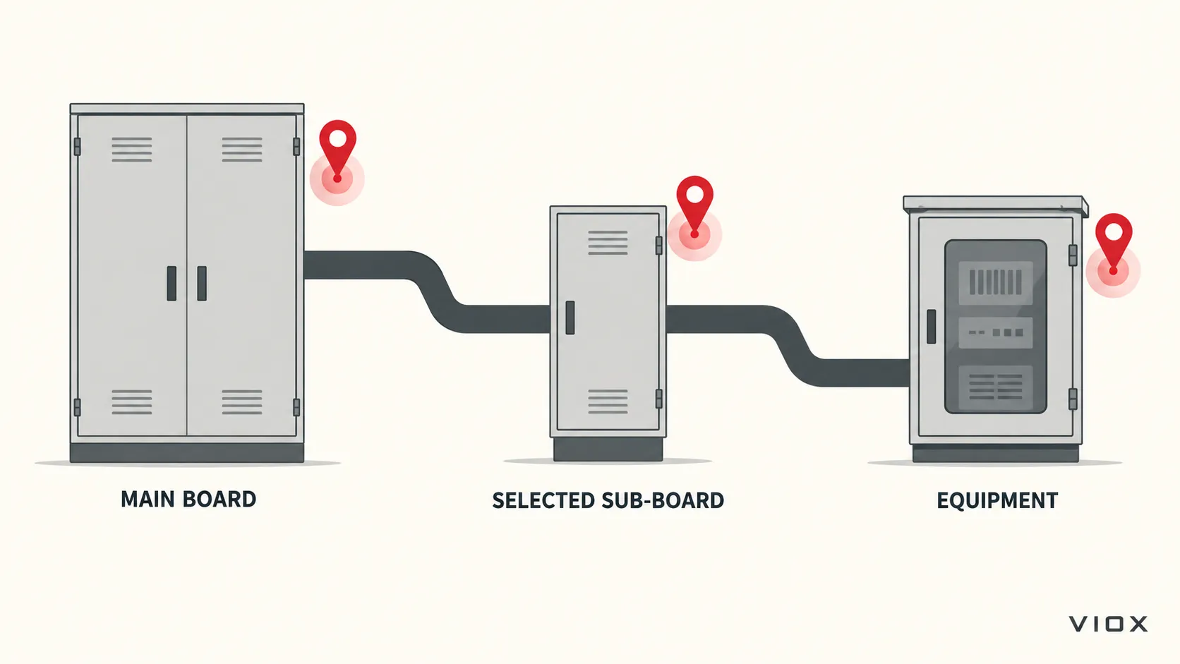
The diagram is a location map, not a connection schematic. An SPD at B or C is not automatically needed because the symbol appears on a drawing. Conversely, an SPD at A does not prove that the voltage at a distant control input will meet the equipment’s withstand objective. IEC 61643-12:2020 explicitly covers SPD selection, location and coordination; the detailed assessment belongs to the installation design.
Start at the incoming main board
The incoming board is normally the first candidate because it is where the supply enters the protected distribution system. Place the device so its complete connection path to the relevant conductors and bonding point can be kept appropriately short and direct while retaining safe access, required clearances, suitable enclosure conditions and the product’s specified protective device. The physically nearest spare DIN-rail position is not automatically the electrically best or permitted position.
Before selecting a main-board SPD, record whether the candidate point is upstream or downstream of the service overcurrent device. This distinction is especially important for a US-market UL 1449 device: UL’s Panelboard Application Guide describes Type 1 SPDs as suitable for designated line- or load-side locations, whereas Type 2 SPDs are intended for the load side of the service overcurrent device, including branch panels. Type 1 does not mean “upstream only.” Do not use a product’s IEC Type label to infer its UL installation permission or listing.
Under the IEC framework, Type or test class describes an SPD’s tested surge duty within a broader system design. IEC 61643-11:2025, used with IEC 61643-01:2024, concerns AC low-voltage SPD requirements and test methods; IEC 61643-12:2020 covers selection and application principles. The applicable national installation rules and product documentation decide the actual permitted location and connection. For the detailed distinction, see Type 1 vs Type 2 vs Type 3 SPDs.
When should you add an SPD at a subpanel?
Add a downstream stage when it controls a different, meaningful electrical boundary, not simply because the building has another enclosure. The table below is a screening tool for deciding which boards deserve a closer engineering check; it is not a universal mandate or a substitute for risk assessment.
| Subpanel condition | Priority for further assessment | Reason |
|---|---|---|
| Long or exposed feeder to another building, outdoor equipment or a distant plant area | High | Cable route and exposure may make the remote board a distinct protection boundary |
| Critical controls, data equipment, safety-related systems or costly downtime served by one board | High | The consequence of equipment-terminal overvoltage may justify a local stage |
| Frequent local switching near sensitive loads | Case-specific | A local SPD may be useful, but the disturbance mechanism and coupling path must be identified |
| Short feeder, ordinary loads, and a verified upstream protection objective | Lower | Another device may provide little incremental benefit unless code, risk or equipment requirements say otherwise |
“High” means investigate, not “install any Type 2 unit.” Confirm the supply and earthing arrangement at that board, the available short-circuit current, the SPD’s maximum continuous operating voltage (Uc or MCOV as applicable), its protective voltage and discharge-current declarations, the approved backup protection, and its coordination with the upstream device. A breaker ampere rating or a larger Imax number cannot answer the location question. Use the SPD coordination guide after the candidate nodes are identified.
Does every subpanel need its own SPD?
No blanket answer is technically sound. A facility with many short, similar branch panels may not need a separate SPD at each one; a single remote panel feeding exposed or mission-critical equipment may warrant one. Local code, project risk assessment and the protected equipment’s requirements can change that decision. Avoid both “one at the main is always enough” and “fit one to every panel” as universal design rules.
Place the final stage at the equipment boundary when needed
For sensitive equipment, the design target is the voltage at the equipment terminals, not merely the catalogue protection level of an SPD several boards away. Feeder routing, the SPD connection path, bonding, other conductive entry routes and the equipment’s impulse withstand all matter. A local power SPD may be appropriate at an equipment cabinet or disconnect, but a power SPD alone does not address an unprotected data, control or signal line entering the same equipment.
Do not turn the Type 3 label into a universal “within 10 metres of the load” rule. In the US framework, NEMA describes Type 3 as a point-of-utilization category associated with a minimum conductor length from the service panel, not a fixed 10 m maximum distance from the equipment. In an IEC design, decide the final protected zone from the actual installation and the equipment objective, then verify the downstream SPD’s coordination with upstream stages. Detailed distance, voltage and energy checks are covered in the SPD coordination and cascading guide.
Within a panel, the complete connection path matters
Two SPDs of identical rating can give different installed results if one has a much longer path from the bus through its protective device and back to the relevant bonding or reference point. Fast surge current produces additional voltage across connection inductance. The practical instruction is to minimise the complete active surge-current path, avoid unnecessary loops and route conductors as the manufacturer specifies—not to promise a universal number of volts per inch or a single lead-length limit for every product and panel.
The NEMA Surge Protection Institute’s installation guidance explains this lead-length effect and explicitly says to follow the manufacturer’s fuse, breaker and installation instructions. It presents an example installation, not a wiring rule for every SPD. Confirm that the chosen bus, breaker or fuse connection is permitted by the panel and SPD documentation; do not add an unapproved tap or assume a dedicated breaker size from a generic article.
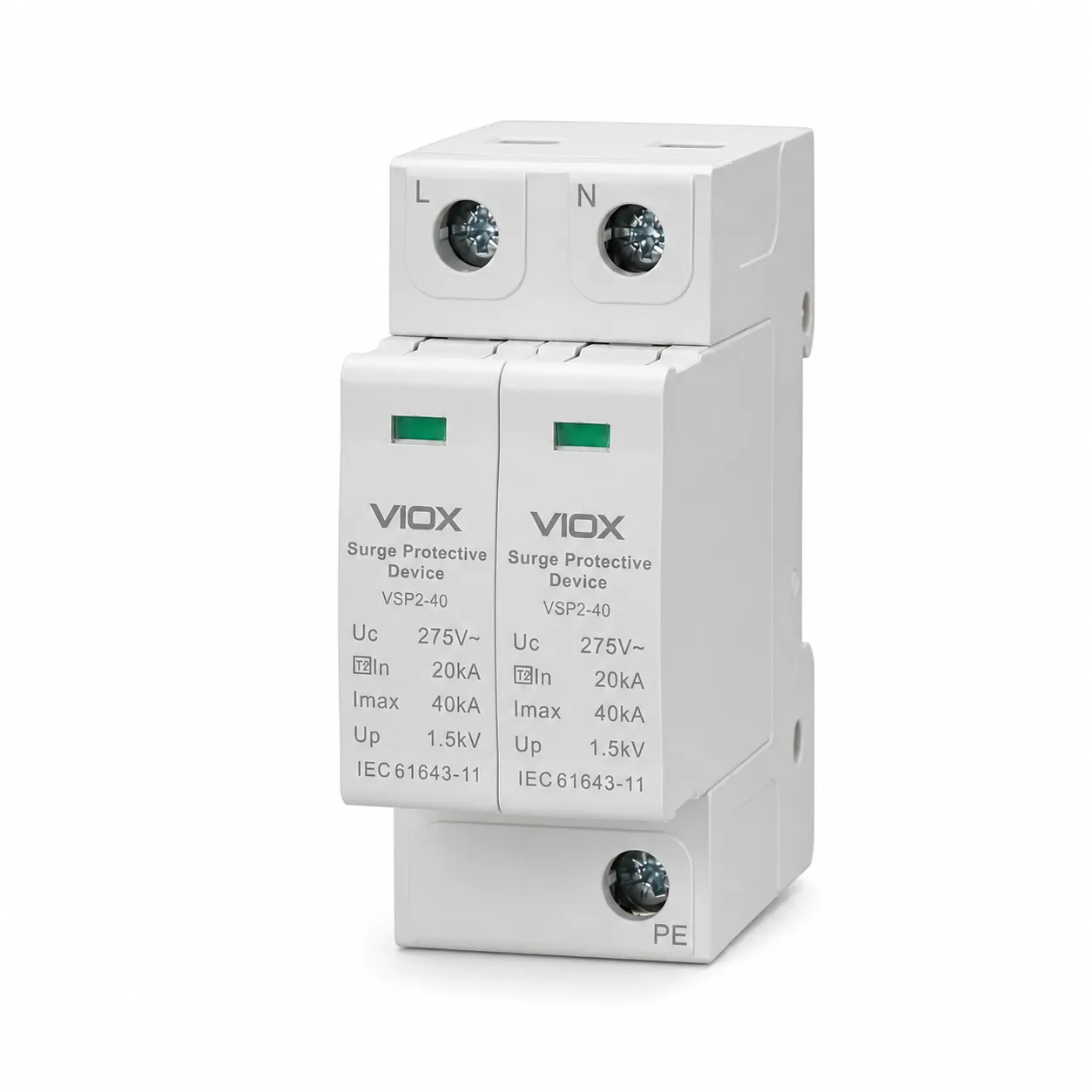
Product appearance only: the photographed VIOX VSP2-40 two-pole unit is not a universal wiring template. Pole count and visible L, N or PE/PEN markings do not establish suitability for a particular TN, TT or IT installation. Check the exact model diagram and documentation.
Pre-installation location check
Before approving a panel position, the designer or qualified installer should be able to answer all of the following:
- Which node is protected? Identify the incoming board, selected sub-board or equipment boundary on the single-line diagram.
- What electrical system exists at that node? Record AC voltage, frequency, phases, neutral availability and TN/TT/IT earthing arrangement. A PEN terminal shown on a product photograph is not a substitute for confirming where PEN actually exists in the installation.
- Which installation framework applies? Use the relevant IEC/national rules or UL/NEC framework without mixing Type permissions.
- Does the exact SPD fit? Verify Type/test duty, Uc/MCOV, protection modes, voltage protection level, discharge-current declarations, short-circuit suitability and environmental conditions from the model documentation.
- Can it be installed correctly? Check permitted mounting and connection, panel space, required backup protection, conductor route, bonding and maintenance access.
- Does it work with adjacent stages? Where two or more SPDs are proposed, verify coordination using manufacturer data and the actual cable paths; physical separation alone does not prove coordination.
If the available documents cannot answer a consequential question, stop at the design stage. The SPD installation requirements guide covers compliance checks, while the wiring guide covers conductor and acceptance details.
From the panel map to a product request
The useful output of this location exercise is a marked-up single-line diagram with A/B/C candidate nodes, the system voltage and earthing at each node, exposure and load priorities, available fault current, and any upstream/downstream SPD already installed. Send that information with the target market and required documentation when evaluating the VIOX SPD range. A two-pole or three-pole product image can show the physical form; it cannot approve the electrical topology, protection mode or installation location on its own.
Sources reviewed
- IEC 61643-12:2020 — selection and application principles
- IEC 61643-11:2025 — AC low-voltage SPD requirements
- IEC 61643-01:2024 — general SPD requirements and test methods
- UL Solutions — Panelboard Application Guide
- NEMA Surge Protection Institute — Correct Installation of Hard-Wired SPD
- NEMA Surge Protection Institute — SPD Type FAQ