On this page
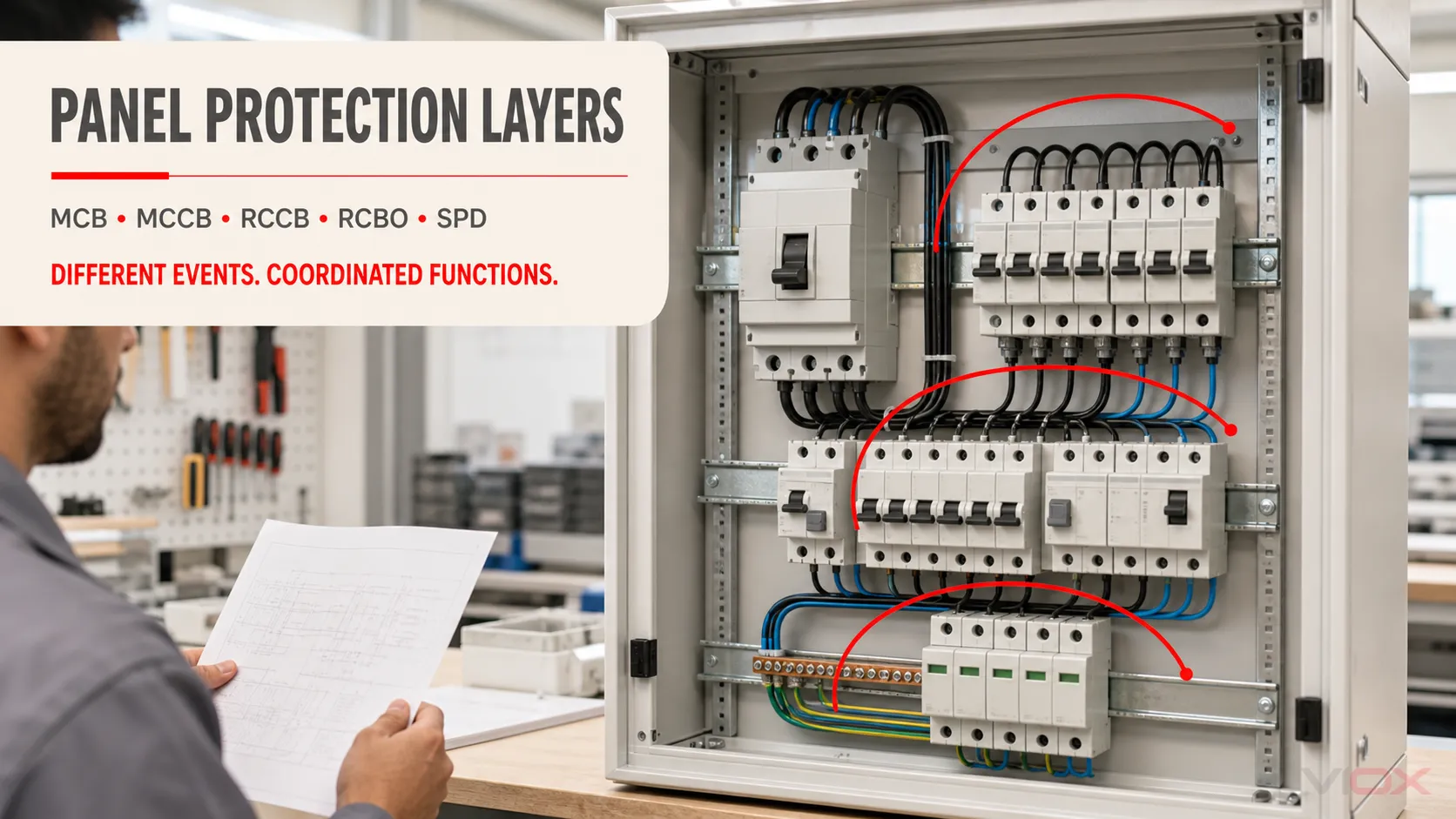
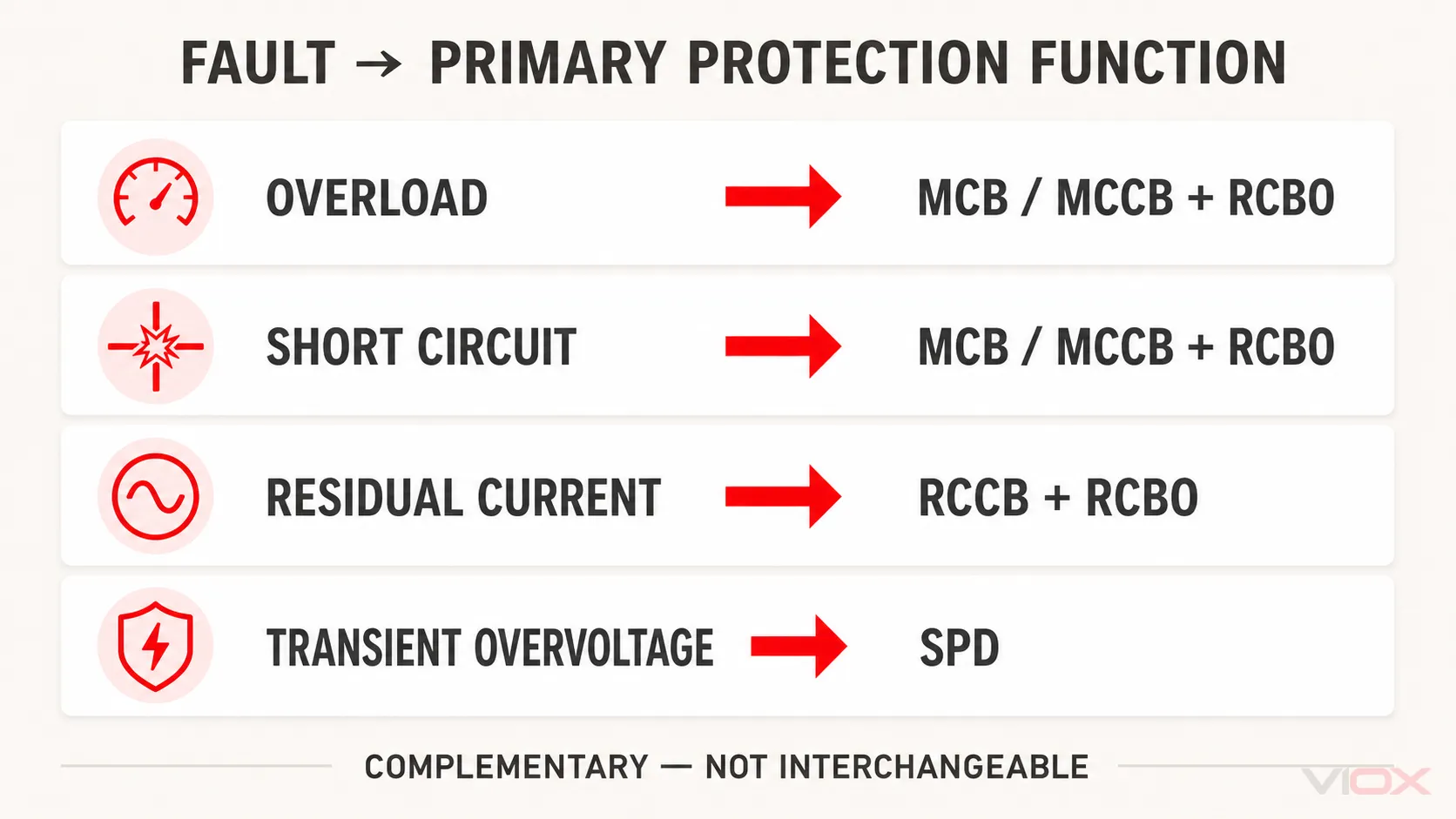
An MCB or MCCB responds to overcurrent, an RCCB responds to residual current, an RCBO combines both functions, and an SPD limits transient overvoltage. These devices protect against different electrical events, so they are complementary rather than interchangeable.
The panel architecture is not proven merely because every device is present. The designer must also verify current and voltage ratings, prospective fault current, residual-current type and sensitivity, short-circuit protection, surge-protection data, neutral boundaries, selectivity, manufacturer coordination tables, and the installation rules that apply to the project.
Fault-to-Device Protection Map
| Electrical event | What changes in the circuit? | MCB / MCCB | RCCB | RCBO | SPD |
|---|---|---|---|---|---|
| Sustained overload | Load current exceeds the circuit’s permitted operating level for long enough to create thermal risk | Primary protective function, subject to the selected trip characteristic and ratings | Not its integral function | Primary protective function | Not its function |
| Short circuit | Fault current rises rapidly along a low-impedance path | Primary protective function within the device’s rated performance | Not an integral breaking function; the RCCB arrangement needs suitable short-circuit protection | Primary protective function within the device’s rated performance | Not the primary short-circuit protective device |
| Residual current / earth leakage | Outgoing and returning currents no longer sum to zero through the sensing core | A standard overcurrent-only device does not provide this function | Primary protective function | Primary protective function | Not its function |
| Transient overvoltage | A short-duration voltage surge appears on the system | Does not normally limit the surge voltage to the protected equipment | Does not normally limit the surge voltage | Does not normally limit the surge voltage | Limits transient overvoltage by diverting or limiting surge current within its declared capability |
This map is functional, not a complete specification. For example, “RCCB present” does not prove the correct residual-current waveform type, and “SPD present” does not prove the correct SPD Type, Uc, Up, discharge-current rating, back-up protection, or connection arrangement.
Why One Device Cannot Cover Every Electrical Event
The devices use different detection and interruption models. Their labels may appear side by side in a distribution board, but they are not measuring the same condition.
MCB and MCCB: current magnitude over time
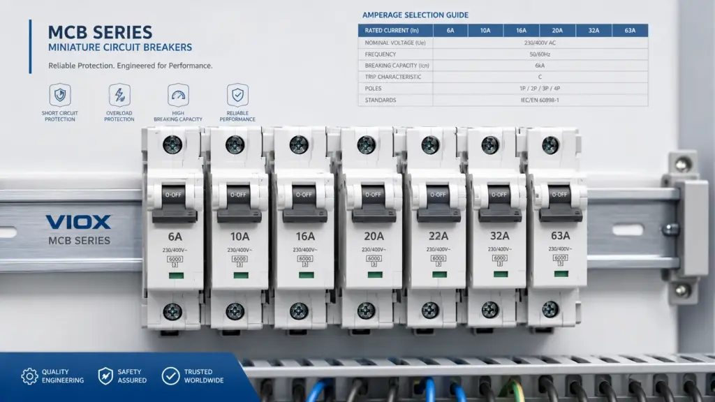
A Miniature Circuit Breaker (MCB) or Molded Case Circuit Breaker (MCCB) opens when the current and time relationship reaches its trip characteristic. The protected circuit, available fault current, breaking capacity, conductor requirements, and device settings or curve determine whether the overcurrent layer is suitable.
In a small final distribution board, MCBs commonly protect outgoing circuits. An MCCB may instead serve an incomer, feeder, or higher-duty distribution circuit when its ratings and adjustable functions suit that position. That placement is only a system example; it is not a substitute for an MCB, MCCB, RCCB and RCBO comparison or a project-specific protection study.
RCCB and RCBO: residual-current balance
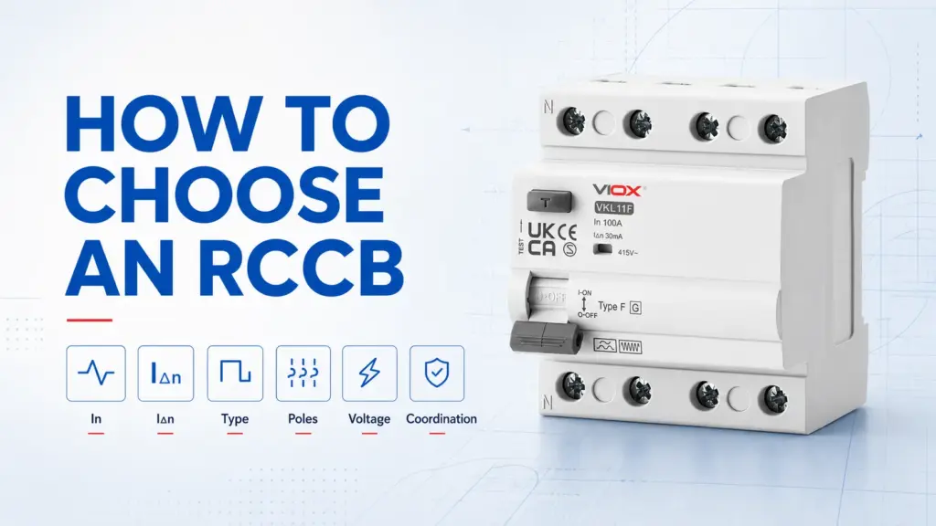
A Residual Current Circuit Breaker (RCCB) monitors the vector sum of current in the live conductors passing through its sensing core. Under normal conditions, outgoing and returning current balance. A residual current indicates that some current is returning by another path, and the device operates when its defined residual-current conditions are met.
IEC 61008-1:2024 covers RCCBs without integral overcurrent protection for household and similar uses. This is the important system boundary: an RCCB does not replace the overcurrent layer. Its rated current In is a current-carrying rating, not an overload trip setting.
An RCBO adds integral overload and short-circuit protection to the residual-current function. IEC 61009-1:2024 covers this combined household and similar-use device class. Combining functions can improve circuit subdivision, but it does not remove the need to select the correct residual-current type, IΔn, poles, voltage, trip characteristic, breaking capacity, and coordination with the rest of the installation.
For the residual-current mechanism, operating boundaries, and terminology, use the dedicated What Is an RCCB guide.
SPD: transient-voltage limitation
A Surge Protective Device (SPD) responds to a transient overvoltage by diverting or limiting surge current so that the resulting voltage at the protected side is reduced. IEC 61643-11:2025 addresses SPDs connected to AC low-voltage power systems and describes devices containing at least one nonlinear component for this purpose.
An SPD is therefore not another overload breaker or residual-current device. It also is not a universal solution for every sustained overvoltage or power-quality problem. Its performance depends on the system, SPD class and ratings, connection path, protective arrangement, and the stress it experiences.
Two Conceptual Distribution-Board Architectures
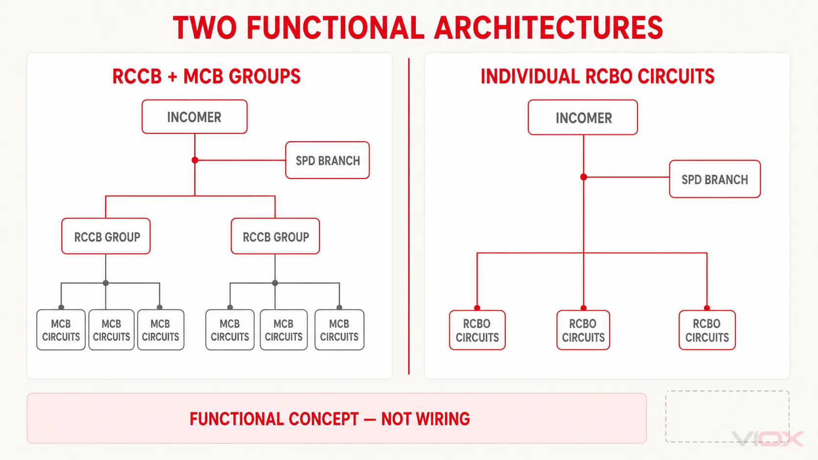
The following architectures show functional relationships only. They are not terminal diagrams, installation sequences, or a universal statement that the SPD must be placed on one side of an RCD. Exact topology depends on the supply and earthing system, local rules, the SPD and RCD documentation, and the required continuity and selectivity.
Architecture A: RCCB groups with downstream MCBs
Supply / upstream overcurrent layer
             |
             +---- SPD branch and its documented protective arrangement
             |
             +---- RCCB group 1 ---- MCB circuits
             |
             +---- RCCB group 2 ---- MCB circuits
Here, the MCBs provide overload and short-circuit protection for outgoing circuits, while each RCCB provides residual-current protection for a group. The design must verify that the RCCB is protected against overload and short-circuit effects using the declared short-circuit protective-device arrangement. ABB’s RCCB guidance, for example, explains that coordination of an RCCB with an MCB must be established through tested manufacturer data rather than assumed from matching ampere markings.
The main operational tradeoff is the fault domain. One residual-current event can disconnect the circuits grouped under the same RCCB. Dividing circuits across groups may improve continuity, but the resulting leakage current, selectivity, neutral separation, and applicable rules still need engineering review.
Architecture B: individual RCBO-protected circuits
Supply / upstream overcurrent layer
             |
             +---- SPD branch and its documented protective arrangement
             |
             +---- RCBO circuit 1
             +---- RCBO circuit 2
             +---- RCBO circuit 3
Each outgoing RCBO combines residual-current and overcurrent protection for its circuit. This can reduce the number of unrelated circuits lost when one branch has a residual-current fault and makes the fault domain easier to identify.
It does not make the board automatically coordinated. The upstream protective device, available fault current, RCBO breaking capacity, RCD type, residual operating current, neutral treatment, SPD arrangement, and any upstream residual-current protection remain part of the design proof.
Functional Coordination Is Not the Same as Selective Coordination
These two checks solve different problems.
| Coordination layer | Question to answer | Evidence required |
|---|---|---|
| Functional coverage | Is each relevant event—overload, short circuit, residual current, and transient overvoltage—addressed by an appropriate protection function? | System risk assessment, circuit requirements, equipment instructions, device functions and applicable installation rules |
| Rating compatibility | Can every device carry, withstand, limit, or interrupt the conditions expected at its installed point? | Rated current and voltage, prospective fault current, breaking or conditional short-circuit data, SPD ratings, conductor and enclosure constraints |
| Selective operation | For a downstream fault, will the intended device operate while suitable upstream devices remain closed where required? | Manufacturer selectivity and cascading tables, time-current data, RCD sensitivity/time-delay coordination and project study |
| Continuity and fault-domain control | How much of the installation is disconnected by one fault or one end-of-life protective device? | Circuit grouping, RCD/RCBO architecture, SPD status/disconnection behavior, maintenance strategy and operational requirements |
RCD selectivity may use circuit subdivision, time delay, sensitivity relationships, or a combination, but it must be verified through the applicable design method and product data. Overcurrent selectivity and back-up protection are also manufacturer- and device-combination-specific; a shared brand name or matching current rating does not prove the result.
SPD coordination introduces another set of checks. The SPD branch and any required short-circuit protective device must be selected together, while the SPD’s interaction with residual-current protection depends on topology, impulse-current immunity, supply system, and manufacturer instructions. This is why a diagram that merely places MCB, RCCB, and SPD icons in a row is not an engineering specification.
What the Designer Must Verify
Use this list to move from a conceptual architecture to a project specification.
| Verification input | Why it changes the architecture or device choice |
|---|---|
| Supply voltage, phases, frequency, and earthing system | Controls pole configuration, conductor treatment, SPD modes of protection, and residual-current protection requirements |
| Load current and conductor protection requirement | Establishes the overcurrent-device rating and characteristic; also sets the current the RCCB must carry |
| Prospective short-circuit current at each device | Must be within the protective device’s declared breaking or conditional short-circuit arrangement |
RCCB or RCBO residual-current type and IΔn |
Must match possible residual-current waveforms, protection objective, equipment instructions, and applicable rules |
| RCCB overload and short-circuit protective arrangement | Requires documented coordination; the RCCB current marking alone is insufficient |
SPD Type and declared Uc, Up, discharge-current data, and back-up protection |
Determines whether the SPD is suitable for the system and the transient-protection objective |
| Neutral and protective-earth boundaries | Incorrect sharing or routing can undermine residual-current operation and create unsafe conditions |
| Selectivity and continuity target | Determines grouping, time relationships, upstream/downstream device combinations, and acceptable outage scope |
| Manufacturer coordination tables and exact model documentation | Converts generic device classes into a verified combination |
| National installation rules and equipment instructions | Product standards define devices; installation compliance remains project- and market-specific |
For a broader protection-device landscape, start with the types of circuit breakers. For the separate relationship between protective earthing, residual-current protection, and surge protection, use the grounding, RCD and surge-protection guide.
When the architecture is established and model documents are available, compare the relevant VIOX MCB, MCCB, RCCB, RCBO, and SPD families against the completed specification. Product availability does not replace the coordination study or local compliance review.
Technical References
- IEC 60898-1:2015 — Circuit-breakers for overcurrent protection for household and similar installations
- IEC 60947-2:2024 — Low-voltage circuit-breakers
- IEC 61008-1:2024 — RCCBs without integral overcurrent protection
- IEC 61009-1:2024 — RCBOs with integral overcurrent protection
- IEC 61643-11:2025 — SPDs connected to AC low-voltage power systems
- Schneider Electrical Installation Guide — Coordination of residual-current protective devices
- NEMA Surge Protection Institute — How SPDs work
- ABB — Coordination of MCBs and RCCBs