

On this page
MCCBs do have time-current curves. The answer to why MCCBs don’t have B C D curves is about classification: conventional molded case circuit breakers are not specified using the standardized B/C/D instantaneous bands associated with IEC 60898-1. Instead, obtain the exact trip-unit reference, declared pickup settings and manufacturer’s operating characteristic under IEC 60947-2. Those settings may be fixed or adjustable; thermal-magnetic does not automatically mean fixed, and electronic does not guarantee every adjustment. The practical mistake is ordering a supposed letter equivalent without checking what the particular release actually does.
The Misconception: MCCBs Are Classified on a Different Axis
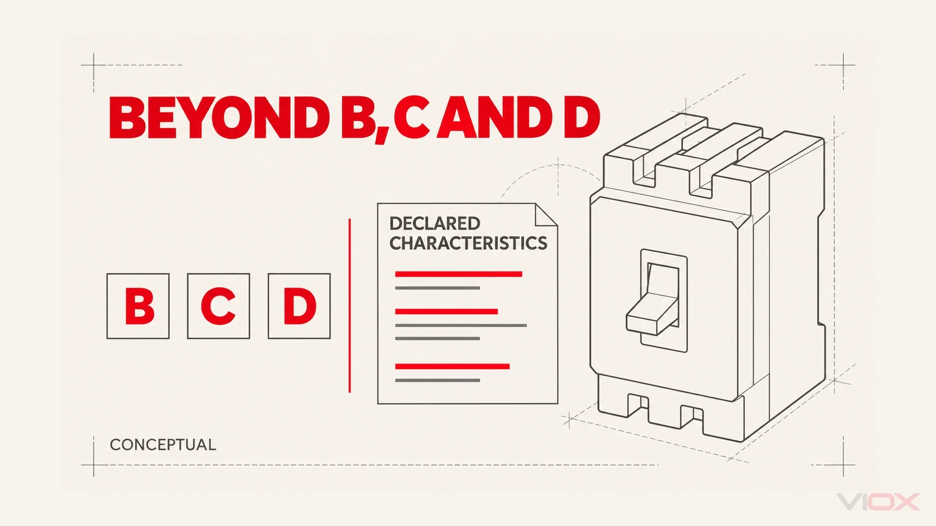
The word “curve” is doing different jobs. A curve letter identifies a standardized instantaneous-current range in the familiar miniature circuit breaker context. A time-current curve describes operating behavior over current and time. A pickup setting identifies a protection threshold. These descriptions are related, but they are not interchangeable.
An MCCB expresses its behavior through an identifiable breaker and release, with a declared operating characteristic. That characteristic provides the information needed for a protection assessment in a more detailed form than the familiar letter designation.
For component background, use the MCCB definition and working-principle guide. Here, the question is narrower: what evidence replaces a requested curve letter?
The standard is also not determined by size alone. Industrial DIN-rail MCBs can carry IEC 60947-2 data alongside familiar curve letters. Product construction, declared standards and characteristic designation belong together when reading the label.
Two Standards, Two Ways to Describe the Characteristic
The following comparison isolates how the familiar AC B/C/D classification differs from a conventional MCCB’s declared characteristic. Both standards also address requirements beyond the tripping information summarized here.
| Question | IEC 60898-1 context | Conventional MCCB under IEC 60947-2 |
|---|---|---|
| Intended setting and users | Household and similar AC installations; ordinary-person operation | Low-voltage switchgear and controlgear; instructed or skilled persons |
| Scope and typical applications | Rated current up to 125 A, voltage up to 440 V between phases and rated short-circuit capacity up to 25 kA | Typical MCCB families span tens to thousands of amperes for feeders, distribution and other applications; this is a product-range description, not a standard current limit |
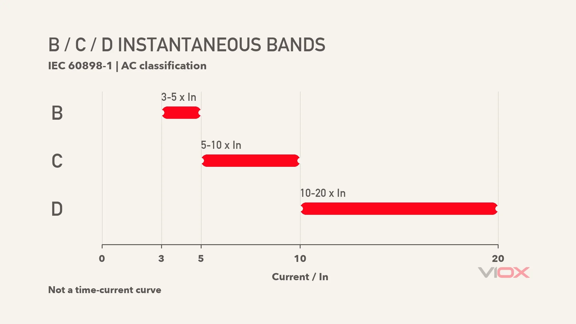
| Familiar instantaneous description | B: 3-5 x In; C: 5-10 x In; D: 10-20 x In | Manufacturer-declared release characteristic and pickup values, not a required B/C/D label |
| Adjustment information | The letter describes a fixed characteristic range | Fixed or adjustable functions according to the exact release |
| Instantaneous verification reference | Defined no-trip/trip test currents for the declared B/C/D characteristic, with specified time conditions | Short-circuit release verification at 80% and 120% of its declared current setting, with the applicable test duration |
| Evidence needed | Declared characteristic, full product data and applicable installation assessment | Exact breaker/release combination, curve and settings documentation |
| What a label cannot prove | Suitability for every load or fault-loop condition | Selectivity, a suitable setting or interchangeability with another trip unit |
Here, In denotes rated current under the relevant product documentation. The B/C/D numbers describe the instantaneous-current classification; the full characteristic also provides overload and time information. The specified test duration is essential to interpreting a no-trip boundary.
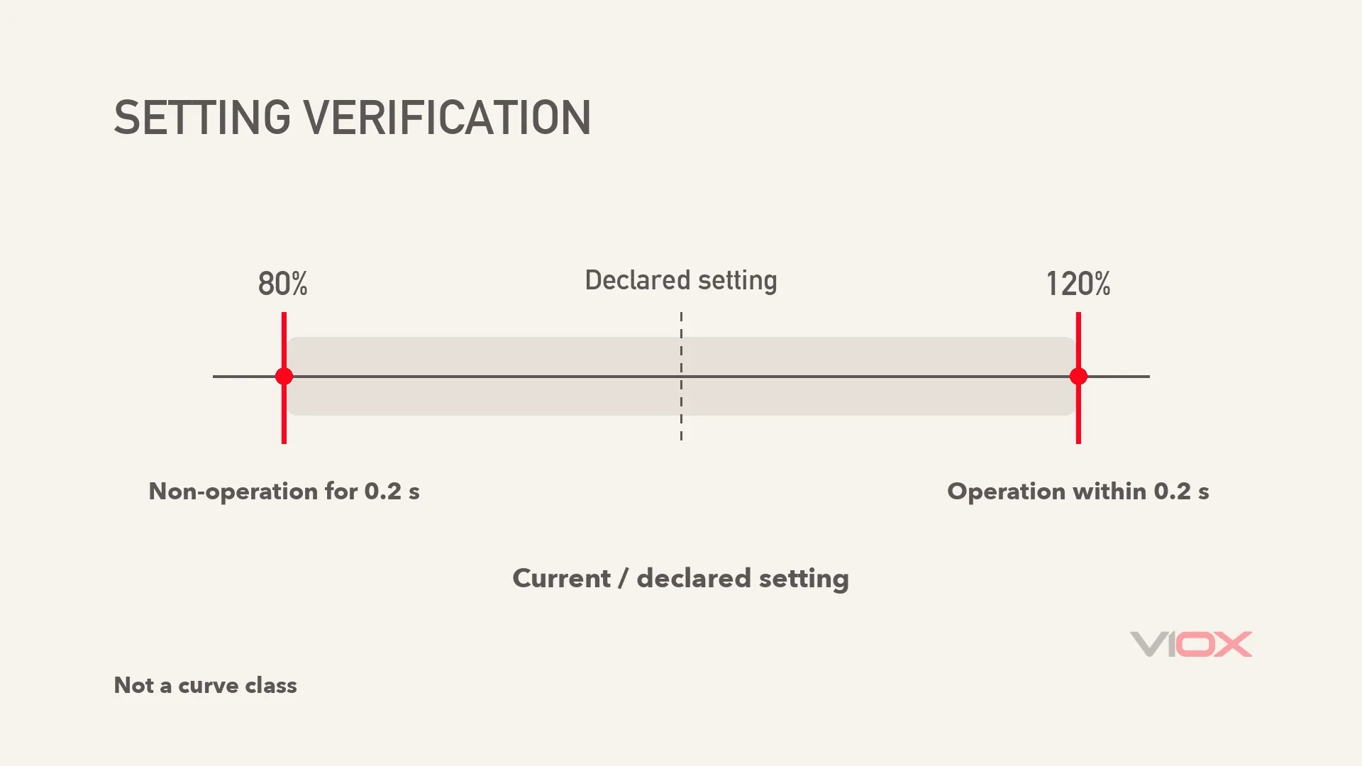
For IEC 60947-2 short-circuit releases, verification is referenced to the declared short-circuit current setting. In the basic instantaneous-release check, the release stays unoperated at 80% of that setting for 0.2 s and operates at 120% within 0.2 s. These are controlled test points, not a promise that 80% can flow indefinitely without another protection function operating.
The applicable test configuration matters: when another short-time-delay release is present, a manufacturer-declared non-tripping duration can replace the basic 0.2 s lower-point duration under the relevant provisions. Definite-time-delay releases have their own timing criteria. The comparison is therefore a standardized characteristic band versus verification around a declared setting, not classification versus precision as the only purpose of either standard.
Why the Intended User Changes the Information Format
IEC 60898-1 addresses household and similar equipment suitable for operation by ordinary persons. A stable letter designation makes the installed characteristic recognizable: an installer, replacement supplier and operator can identify the declared type without interpreting an adjustment schedule. This is a communication advantage, not permission for an unqualified person to select protection without checking the circuit.
IEC 60947-2 addresses equipment intended for instructed or skilled persons. The engineer may need to assess feeder duty, fault current and coordination with downstream devices, so the exact release characteristic and any available settings become important specification inputs. A fixed release can still be the correct engineering choice; adjustability is a product capability rather than a prerequisite for compliance. The difference is the level of declared information available for the system assessment, not a rule that one user chooses a letter and the other always turns a dial.
Why Final Circuits Benefit From Standardized Bands
A final circuit may supply equipment whose starting current differs substantially from its running current. A protection characteristic has to tolerate permitted starting events while still disconnecting faults within the installation’s requirements. Sensitivity and inrush tolerance therefore have to be considered together.
A lower instantaneous threshold can conflict with starting current. A higher threshold requires sufficient fault current to reach that part of the characteristic when rapid operation is needed. If it does not, the remaining protection behavior must still meet the required disconnection conditions. Increasing the letter is therefore not a general cure for unwanted tripping.
The fixed bands give a recognizable vocabulary for comparing appropriate MCB characteristics. The actual starting behavior comes from the equipment: lighting, for example, can include loads with substantial inrush. That equipment information and the available fault current establish whether a particular characteristic is suitable.
For heating, motors and mixed circuits, the designer checks product characteristics, circuit impedance, conductors and the relevant installation rules. The standardized band makes the result easier to specify and recognize once those circuit conditions have been assessed.
For the separate reading and selection task, see how to read trip curves and choose B, C or D. The point here is why the letters are useful standardized shorthand, not how to choose one for a particular circuit.
Why Distribution Protection Needs More Than a Letter
An MCCB can protect a feeder serving several downstream circuits, a final circuit or a motor feeder. Its place in the system determines the assessment required. A feeder’s combined duty and downstream protective arrangement usually require more information than a single load label conveys.
At a feeder, the engineer may need to coordinate overload behavior, short-circuit pickup and any intentional delay with downstream protective devices. A single letter cannot describe all those relationships. The actual characteristic and the combination of devices are what matter.
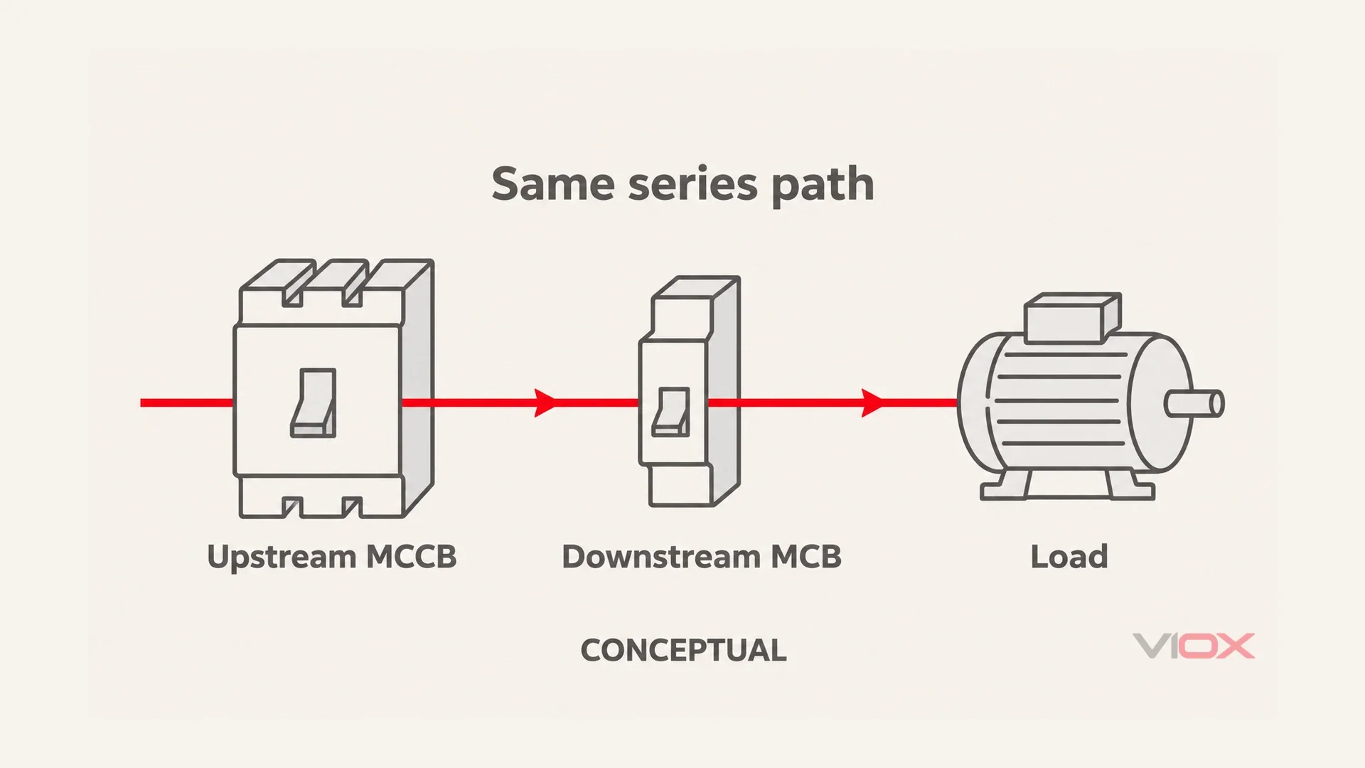
A downstream MCB does not absorb starting inrush. While it remains closed, the upstream path carries the downstream starting current too. Aggregation and which loads start together can change the feeder duty, but an upstream assessment cannot simply ignore the events because the downstream breaker has an appropriate letter.
Selectivity and backup protection answer different questions. Selectivity concerns which device operates for a fault. A backup arrangement concerns the verified fault-interruption performance of a combination. Each requires evidence for the proposed devices and their operating conditions.
Published coordination information and the relevant system assessment establish that evidence. Settings and time-current characteristics describe the response; current-limiting behavior and manufacturer combination data can also determine interaction at high fault levels. Generic curve spacing alone leaves that part of the assessment incomplete.
What the MCCB’s Declared Pickup Actually Means
For a thermal-magnetic release, magnetic pickup is established by the design and calibration of the electromagnetic mechanism. Some units provide a fixed pickup; others provide a permitted mechanical adjustment. Both arrangements are described by the particular release’s data, so thermal-magnetic technology by itself does not establish whether pickup is adjustable.
Read the declaration together with its reference current. A multiple of trip-unit rated current and a multiple of an adjusted long-time setting can represent different thresholds. The manufacturer’s symbols identify which current is being used; the 80%/120% verification is referenced to the declared short-circuit setting itself.
The distances from the declared setting to those two verification points are minus and plus 20%. That arithmetic explains the familiar tolerance-band illustration. More precisely, the figure below shows verification boundaries, not a measured distribution of actual trip points or an additional standard curve class. Its horizontal axis is current divided by the declared setting; the earlier B/C/D chart uses current divided by In, so the apparent widths are not directly comparable.
For the detailed parameter vocabulary and reference-current symbols, use the MCCB trip-unit settings reference.
Motor-oriented releases may use higher declared pickup to accommodate starting duty; see the MCCB instantaneous-trip application guide for that separate task, with the exact manufacturer’s characteristic governing any selection. A higher pickup still does not create a standardized “D-curve MCCB.”
Electronic Trip Units: From Labels to Declared Settings
Electronic sensing and processing allow a release to implement protection functions through defined settings. Long-time, short-time and instantaneous functions are often abbreviated L, S and I. That capability can provide more ways to describe the required response than a curve letter alone.
The unit’s instructions define which controls are available. An electronic release may expose discrete settings, restrict combinations or omit an adjustable function. Its reference current, delay behavior and dependencies explain how the controls combine into the declared characteristic.
This changes the specification question from “Which letter?” to “Which functions and declared characteristic does this application require?” A permissible adjustment remains consistent with conductor protection, fault clearing and coordination requirements, rather than merely suppressing unwanted trips.
The broader purchase decision belongs in thermal-magnetic versus electronic MCCB selection. Here, technology matters only because it changes how the characteristic is declared and what adjustment, if any, is available.
How MCCBs Are Actually Classified
An MCCB description contains several independent pieces of information. Reading each field against its own definition prevents the repeated letters from becoming false equivalents.
| Classification axis | What to establish | What not to infer |
|---|---|---|
| Selectivity category A | Not specifically provided with the category B short-time-delay selectivity arrangement | That no selective combination is possible; documented selectivity may still exist |
| Selectivity category B | Intended short-time-delay selectivity behavior with a declared short-time withstand capability, Icw | That every downstream device will be selective at every fault level |
| Protection application | The declared distribution, motor or other application and its complete protection arrangement | A universal instantaneous multiple based on the application name |
| Release technology | Thermal-magnetic, magnetic-only or electronic, with the actual functions specified | That every technology has the same functions or adjustment range |
Selectivity category B is not MCB curve B. The repeated letter has a different meaning. A category declaration concerns the relevant selectivity arrangement and withstand behavior, not the B instantaneous band in the earlier graphic.
The application description also identifies which functions the complete arrangement needs. A magnetic-only release supplies short-circuit protection, while the required overload function must be established elsewhere in that arrangement.
The broader breaker-family comparison addresses distinctions beyond this curve-and-setting question. Keeping construction, application and characteristic terminology separate makes the final specification clearer.
What This Means When You Specify
For an MCB, identify the required product standard and full characteristic rather than choosing a letter from a load name alone. For an MCCB, request the exact breaker and trip-unit combination, whether pickup is fixed or adjustable, its declared values or ranges and its complete time-current data.
For a coordinated installation, add the applicable selectivity category and the manufacturer’s evidence for the proposed combination. A suitable substitution preserves the required protection functions, breaking performance and installation conditions as well as rated current and pickup behavior.
This is the useful replacement for asking for a “C-curve” or “D-curve” MCCB: an identifiable release and documented behavior under the conditions that matter. Start a product enquiry through VIOX’s MCCB product category, requesting the exact release documentation for the application.
FAQ
Can I find a “D-curve MCCB” for a motor feeder?
Do not treat that description as a standardized IEC 60947-2 MCCB class. Ask for the exact release, declared characteristic and application evidence. Raising a pickup or selecting a motor-oriented release does not, by itself, make it equivalent to an IEC 60898-1 D characteristic.
Does an MCCB have a trip curve at all?
Yes. Its time-current characteristic describes operating behavior, with the relevant settings and tolerances. The absence of a B/C/D class does not mean absence of a curve. Obtain data for the exact breaker and release, not a generic family illustration.
Why is my thermal-magnetic MCCB’s instantaneous trip not adjustable?
That particular release may have a fixed magnetic pickup established by its design and calibration. Other thermal-magnetic units can provide adjustment. Check the exact documentation before assuming that electronic technology is necessary or that a control can be modified.
What replaces the curve letter when I order an MCCB?
Specify the exact trip-unit type, declared pickup values or adjustment capability, relevant selectivity category and time-current characteristic. These describe different aspects of the protection. They must agree with the intended application and coordination assessment.
Are B/C/D curves used outside IEC 60898-1?
The letters can appear in manufacturer designations and on DIN-rail MCBs that also carry IEC 60947-2 data. That does not make them a mandatory MCCB classification under IEC 60947-2. Read the declared standards, device type and specific characteristic together rather than transferring a label automatically.
Sources
- IEC 60898-1:2015+AMD1:2019 – Circuit-breakers for household and similar AC installations.
- IEC 60947-2:2024 – Low-voltage switchgear and controlgear: Circuit-breakers.
These references identify the governing product-standard context. They do not replace the applicable standard text, exact product instructions or the installation’s protection assessment.