? Key Components and Working Principle")
In modern electrical distribution systems, ensuring uninterrupted power supply while maintaining safety and efficiency is paramount. The Ring Main Unit (RMU) has emerged as a critical component in medium-voltage power distribution networks, particularly in urban environments where space constraints and reliability demands are high. This comprehensive guide explores the fundamentals, components, working principles, and applications of RMUs in electrical distribution systems.
Key Takeaways
- Ring Main Units (RMUs) are compact, factory-assembled switchgear designed for medium-voltage (7.2kV-36kV) power distribution in ring-type networks
- RMUs provide redundant power paths through closed-loop configuration, ensuring continuous supply even during component failures
- Core components include load break switches, circuit breakers, fuses, busbars, and protection devices working in coordination
- RMUs offer space-saving design (up to 60% smaller than traditional switchgear), making them ideal for urban installations
- Compliance with IEC 62271-200 and other international standards ensures safety and reliability
- Applications span urban grids, industrial facilities, commercial buildings, and renewable energy systems
- Modern RMUs integrate smart monitoring capabilities for remote control and predictive maintenance
What is a Ring Main Unit (RMU)?
A Ring Main Unit (RMU) is a factory-assembled, metal-enclosed switchgear device designed specifically for medium-voltage electrical distribution networks operating in a ring or loop configuration. According to IEC 62271-200 standards, RMUs serve as load connection points in ring-type distribution systems, integrating multiple switching, protection, and isolation functions within a single compact enclosure.

The term “Ring Main Unit” originates from its primary application in ring-type distribution networks, where power can flow from multiple directions. This configuration creates redundancy—if one section of the network fails, electricity automatically reroutes through alternative paths, maintaining continuous supply to connected loads.
RMUs typically operate at voltage levels ranging from 7.2kV to 36kV, with the most common ratings being 12kV, 17.5kV, and 24kV. They are designed to handle rated currents between 630A to 1250A for busbar feeders, though some specialized units can accommodate up to 3150A.
Unlike traditional switchgear that requires significant installation space and complex assembly, RMUs are pre-assembled and tested at the factory, arriving as ready-to-install units. This design philosophy significantly reduces installation time, minimizes on-site errors, and ensures consistent quality across deployments.
Core Components of a Ring Main Unit
Understanding the internal architecture of an RMU is essential for appreciating its functionality. Each component plays a specific role in ensuring safe, reliable power distribution.
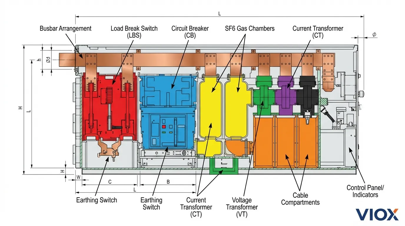
1. Load Break Switch (LBS)
The load break switch is the primary switching device in most RMUs, capable of making and breaking circuits under normal load conditions. Unlike simple isolators, load break switches can interrupt load currents (typically up to 630A) but are not designed to interrupt fault currents.
Key characteristics:
- Making capacity: Ability to close onto a faulted circuit
- Breaking capacity: Interrupts normal load current
- Mechanical endurance: Typically 10,000 operations
- Insulation medium: SF6 gas or vacuum technology
Load break switches work in conjunction with fuses to provide complete protection. When a fault occurs, the fuse operates first to interrupt the fault current, and the load break switch then isolates the circuit.
2. Circuit Breaker
In more advanced RMU configurations, vacuum circuit breakers (VCBs) replace the load break switch-fuse combination. Circuit breakers offer superior performance:
- Fault interruption capability: Can break short-circuit currents (typically 16kA to 25kA)
- Reclosing capability: Can be reset and reused after fault clearing
- Longer service life: Up to 30,000 mechanical operations
- Maintenance advantages: No fuse replacement required
Circuit breakers are particularly valuable in applications requiring frequent switching operations or where automatic reclosing is desired, such as in automatic transfer switch systems.
3. Fuse Switch Disconnector
The fuse switch disconnector combines isolation and protection functions in a single device. High-voltage fuses provide:
- Overcurrent protection: Rapid response to overload conditions
- Short-circuit protection: Interrupts fault currents up to their rated breaking capacity
- Transformer protection: Specifically sized for distribution transformer protection
- Cost-effectiveness: Lower initial investment compared to circuit breakers
Fuses used in RMUs must comply with IEC 60282-1 standards for high-voltage fuses, ensuring coordinated protection with upstream and downstream devices.
4. Busbars
Busbars form the electrical backbone of the RMU, providing low-resistance pathways for current flow between different sections. Modern RMUs typically feature:
- Material: Electrolytic copper or aluminum alloy
- Configuration: Single busbar or double busbar systems
- Current rating: 630A to 3150A depending on application
- Surface treatment: Tin-plated or silver-plated for enhanced conductivity
Double busbar configurations offer increased reliability—if one busbar fails, the system continues operating on the secondary busbar. This design principle mirrors the redundancy philosophy of ring network topology. For more on busbar technology, see our guide on busbar selection.
5. Earthing Switch
The earthing switch (or grounding switch) provides a critical safety function by creating a deliberate connection to ground. This device:
- Ensures safe working conditions during maintenance
- Discharges residual voltage from cables and equipment
- Provides visible isolation confirmation
- Prevent accidental energization
Earthing switches must be mechanically interlocked with load break switches or circuit breakers to prevent simultaneous closure, which would create a direct short circuit.
6. Current Transformers (CTs) and Voltage Transformers (VTs)
Instrument transformers enable measurement and protection functions:
Current Transformers:
- Step down high currents to measurable levels (typically 5A or 1A secondary)
- Provide input for protection relays and metering
- Multiple cores for different protection and metering functions
- Accuracy classes per IEC 61869 standards
Voltage Transformers:
- Step down high voltages to safe levels (typically 110V or 100V secondary)
- Enable voltage measurement and earth fault detection
- Provide synchronization signals for parallel operation
7. Protection Relays and Control Systems
Modern RMUs incorporate intelligent electronic devices (IEDs) that provide:
- Overcurrent protection: Time-delayed and instantaneous elements
- Earth fault protection: Sensitive detection of ground faults
- Directional protection: Determines fault direction in ring networks
- Communication interfaces: IEC 61850, Modbus, DNP3 protocols for SCADA integration
Advanced protection relays can implement adaptive protection schemes that adjust settings based on network configuration, similar to principles used in circuit breaker coordination.
8. Insulation Medium
RMUs utilize different insulation technologies:
SF6 Gas-Insulated:
- Superior dielectric strength
- Compact design
- Sealed-for-life construction
- Environmental considerations (high GWP)
Solid-Insulated (Air or Resin):
- Environmentally friendly
- No gas handling requirements
- Slightly larger footprint
- Growing market preference
Vacuum-Insulated:
- Used primarily in circuit breaker chambers
- Excellent arc-quenching properties
- Long service life
Working Principle of Ring Main Units
The operational philosophy of RMUs centers on maintaining continuous power supply through intelligent network topology and coordinated protection.
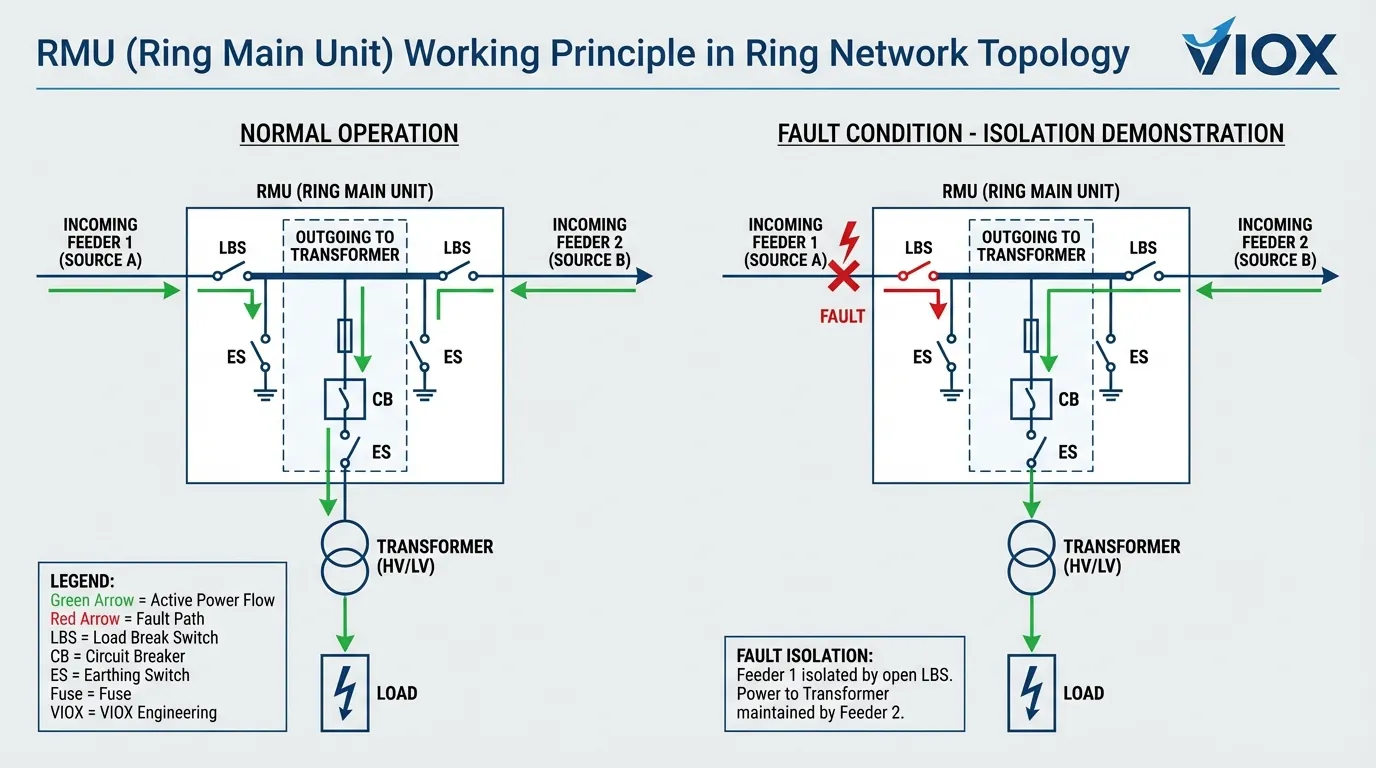
Ring Network Configuration
In a typical ring network:
- Dual-feed capability: Each RMU connects to two incoming feeders from different sources
- Loop topology: Multiple RMUs interconnect to form a closed ring
- Bidirectional power flow: Electricity can reach any point from either direction
- Sectionalizing capability: Each RMU can isolate specific network sections
This configuration ensures that even if one feeder fails, all loads continue receiving power through the alternative path—a principle known as N-1 redundancy.
Normal Operation Sequence
During standard operation:
- Both incoming feeders are energized: Power flows through the ring from multiple sources
- Load break switches remain closed: Maintaining circuit continuity
- Outgoing feeders supply distribution transformers: Stepping voltage down for end users
- Protection relays monitor continuously: Detecting abnormal conditions
- Earthing switches remain open: Ensuring no ground connection during operation
Fault Condition Response
When a fault occurs, the RMU responds through coordinated protection:
- Fault detection: Protection relays identify overcurrent or earth fault
- Fuse operation or breaker tripping: Interrupts fault current within milliseconds
- Fault isolation: Affected section disconnects from healthy network
- Alternative path activation: Power reroutes through ring configuration
- Alarm generation: Notifies operators of fault location
This rapid response minimizes the affected area and duration of outages, a critical advantage in urban distribution networks.
Interlocking Mechanisms
RMUs incorporate sophisticated mechanical and electrical interlocks to prevent unsafe operations:
- Load break switch and earthing switch: Cannot close simultaneously
- Incoming and outgoing switches: Coordinated operation sequences
- Circuit breaker and disconnector: Proper isolation before maintenance
- Door interlocks: Prevent access to live parts
These safety features align with principles discussed in our MCB lockout tagout procedures.
Types of Ring Main Units
RMUs are classified based on several criteria:
By Insulation Medium
| Type | Insulation | Advantages | Disadvantages | Typical Applications |
|---|---|---|---|---|
| SF6 Gas-Insulated | Sulfur hexafluoride gas | Compact size, excellent dielectric properties, sealed-for-life | Environmental concerns (GWP 24,300), gas monitoring required | Urban substations, space-constrained installations |
| Solid-Insulated | Epoxy resin or air | Eco-friendly, no gas handling, maintenance-free | Slightly larger footprint, higher initial cost | Green projects, environmentally sensitive areas |
| Air-Insulated | Atmospheric air | Simple design, easy maintenance, lowest cost | Large size, limited outdoor use | Indoor installations, industrial facilities |
| Vacuum-Insulated | Vacuum chambers | Excellent arc interruption, long life, compact | Higher technology complexity | Premium applications, critical infrastructure |
By Configuration
2-Section RMU:
- Two incoming feeders
- Basic ring network node
- Most common configuration
3-Section RMU:
- Two incoming feeders + one outgoing feeder
- Standard distribution point
- Feeds single distribution transformer
4-Section RMU:
- Two incoming feeders + two outgoing feeders
- Serves multiple transformers
- Enhanced flexibility
6-Section RMU:
- Multiple incoming and outgoing combinations
- Bus coupler section
- Complex distribution nodes
By Mounting Type
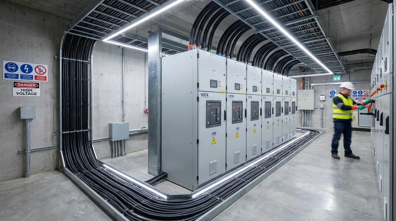
Indoor RMUs:
- IP3X to IP4X protection
- Controlled environment installation
- Lower environmental stress
Outdoor RMUs:
- IP54 to IP65 protection
- Weather-resistant enclosure
- UV-stabilized materials
- Corrosion-resistant coating
Technical Specifications and Standards
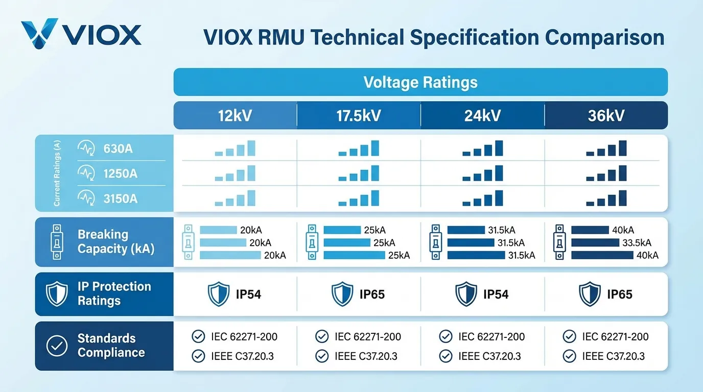
Key Electrical Parameters
| Parameter | Typical Range | Standard Reference |
|---|---|---|
| Rated Voltage | 7.2kV – 36kV | IEC 62271-1 |
| Rated Current (Busbar) | 630A – 3150A | IEC 62271-200 |
| Rated Current (Feeder) | 200A – 630A | IEC 62271-200 |
| Short-Circuit Breaking Capacity | 16kA – 25kA | IEC 62271-100 |
| Short-Circuit Making Capacity | 40kA – 63kA (peak) | IEC 62271-100 |
| Power Frequency Withstand Voltage | 28kV – 95kV (1 min) | IEC 60060-1 |
| Lightning Impulse Withstand Voltage | 60kV – 170kV (peak) | IEC 60060-1 |
Applicable Standards
International Standards:
- IEC 62271-200: AC metal-enclosed switchgear and controlgear (primary standard for RMUs)
- IEC 62271-100: High-voltage alternating-current circuit-breakers
- IEC 62271-103: Switches for rated voltages above 1 kV
- IEC 61869: Instrument transformers
- IEC 60529: IP protection classification
Regional Standards:
- IEEE C37.20.3: Metal-enclosed interrupter switchgear (North America)
- GB 3906: AC metal-enclosed switchgear (China)
- BS EN 62271-200: British implementation of IEC standards
Understanding these standards is crucial for procurement and compliance, similar to considerations in MCCB selection.
Applications of Ring Main Units
Urban Power Distribution
RMUs are the backbone of modern city electrical networks:
- Underground substations: Compact design fits in limited space
- High-rise buildings: Reliable power for critical infrastructure
- Shopping centers: Continuous supply for commercial operations
- Transportation hubs: Airports, metro stations, railway terminals
The ring configuration ensures that maintenance on one section doesn’t disrupt service to other areas—a critical requirement in densely populated urban environments.
Industrial Facilities
Manufacturing and processing plants rely on RMUs for:
- Process continuity: Minimizes production downtime
- Equipment protection: Coordinated protection for expensive machinery
- Flexible expansion: Modular design accommodates growth
- Safety compliance: Meets stringent industrial safety standards
Industrial applications often require integration with motor control systems and contactors.
Commercial Buildings
Office complexes, hotels, and data centers benefit from:
- High reliability: Supports mission-critical operations
- Compact footprint: Maximizes usable building space
- Low maintenance: Reduces operational costs
- Smart integration: Connects with building management systems
Renewable Energy Systems
RMUs play an increasing role in sustainable energy infrastructure:
- Solar farms: Connects multiple PV combiner boxes to the grid
- Wind parks: Collects power from distributed generators
- Battery storage systems: Integrates energy storage with distribution
- Microgrids: Enables islanded operation and grid connection
The bidirectional power flow capability of RMUs makes them ideal for renewable energy applications where power may flow in either direction.
Infrastructure Projects
Critical infrastructure deployments include:
- Water treatment plants: Ensures continuous operation of essential services
- Hospitals: Provides reliable power for life-safety systems
- Telecommunications: Supports network infrastructure
- Government facilities: Meets security and reliability requirements
Advantages of Ring Main Units
1. Enhanced Reliability
The ring network topology provides inherent redundancy. Statistical analysis shows that RMU-based networks achieve 99.95% availability compared to 99.5% for radial networks—translating to approximately 4 hours less downtime per year.
2. Space Efficiency
RMUs occupy 40-60% less space than equivalent traditional switchgear installations. A typical 3-section RMU measures approximately 1200mm (W) × 1400mm (D) × 2100mm (H), compared to 3000mm × 2000mm × 2500mm for conventional switchgear.
3. Reduced Installation Time
Factory assembly and testing mean:
- 50-70% faster installation compared to site-assembled switchgear
- Reduced on-site labor requirements
- Minimized installation errors
- Shorter project timelines
4. Lower Maintenance Requirements
Sealed-for-life designs, particularly SF6 gas-insulated units, require minimal maintenance:
- No routine gas handling
- Extended service intervals (typically 5-10 years)
- Reduced maintenance costs (30-40% lower than traditional switchgear)
- Higher equipment availability
5. Improved Safety
Multiple safety features protect personnel and equipment:
- Metal-enclosed construction: Prevents accidental contact with live parts
- Interlocking mechanisms: Prevents unsafe operations
- Arc-resistant designs: Available for high-risk applications
- Clear status indication: Visual confirmation of switch positions
6. Flexibility and Scalability
Modular design enables:
- Easy network expansion: Add sections without major reconfiguration
- Adaptable configurations: Customize for specific applications
- Future-proof design: Accommodate changing load requirements
- Standardized interfaces: Simplify integration with existing infrastructure
RMU vs. Traditional Switchgear: Comparison
| Feature | Ring Main Unit (RMU) | Traditional Switchgear |
|---|---|---|
| Configuration | Compact, integrated unit | Separate components, assembled on-site |
| Size | Small footprint (1-2 m²) | Large footprint (4-8 m²) |
| Installation | Factory-assembled, quick installation | Site assembly required, longer installation |
| Typical Application | Ring networks, urban distribution | Radial networks, large substations |
| Voltage Range | 7.2kV – 36kV (medium voltage) | 1kV – 800kV (low to extra-high voltage) |
| Maintenance | Low (sealed units) | Moderate to high |
| Flexibility | Limited expansion options | Highly flexible, easily expandable |
| Cost | Moderate initial cost | Higher initial cost, lower per-unit cost for large installations |
| Reliability | Very high (ring redundancy) | High (depends on configuration) |
| Environmental Protection | IP54 to IP65 standard | Varies (IP3X to IP54) |
This comparison helps in making informed decisions, similar to choosing between RCBO vs RCCB+MCB configurations.
Selection Criteria for Ring Main Units
When specifying an RMU for your project, consider:
1. Electrical Requirements
- Voltage level: Match system nominal voltage
- Current rating: Consider present and future load
- Short-circuit level: Ensure adequate breaking capacity
- Protection requirements: Overcurrent, earth fault, directional
2. Environmental Conditions
- Installation location: Indoor vs. outdoor
- Ambient temperature: Operating range typically -25°C to +40°C
- Altitude: Derating required above 1000m
- Pollution level: Affects insulation requirements
- Seismic requirements: For earthquake-prone regions
3. Network Configuration
- Ring or radial: Determines switching arrangement
- Number of feeders: Incoming and outgoing requirements
- Future expansion: Provision for additional sections
- Integration needs: SCADA, automation systems
4. Standards and Compliance
- Regional standards: IEC, IEEE, GB, etc.
- Utility requirements: Specific utility specifications
- Safety certifications: CE, CCC, UL as applicable
- Environmental regulations: SF6 restrictions in some regions
5. Operational Requirements
- Switching frequency: Affects choice of switching device
- Remote control: Manual vs. motorized operation
- Monitoring needs: Basic indication vs. comprehensive monitoring
- Maintenance access: Space and safety considerations
Installation and Maintenance Best Practices
Installation Guidelines
- Site preparation: Ensure adequate foundation and cable access
- Environmental control: Maintain specified temperature and humidity during installation
- Cable termination: Follow manufacturer specifications for cable preparation
- Grounding: Establish low-resistance earth connection
- Testing: Perform commissioning tests per IEC 62271-200
Maintenance Recommendations
Annual Inspections:
- Visual inspection of enclosure and seals
- Verification of indication and interlocks
- Cleaning of insulators and terminals
- Tightness check of connections
Periodic Testing (3-5 years):
- Insulation resistance measurement
- Contact resistance testing
- Protection relay verification
- Mechanical operation testing
Long-term Maintenance (10+ years):
- Comprehensive electrical testing
- SF6 gas analysis (if applicable)
- Component replacement as needed
- Upgrade of protection and control systems
Proper maintenance extends equipment life and ensures reliable operation, similar to practices outlined in our industrial contactor maintenance guide.
Future Trends in RMU Technology
1. Smart Grid Integration
Modern RMUs increasingly incorporate:
- IEC 61850 communication: Standardized substation automation
- IoT sensors: Real-time condition monitoring
- Predictive analytics: AI-based failure prediction
- Self-healing networks: Automatic fault isolation and restoration
2. Environmental Sustainability
The industry is transitioning toward:
- SF6-free designs: Solid insulation and alternative gases
- Reduced carbon footprint: Energy-efficient manufacturing
- Recyclable materials: End-of-life considerations
- Extended service life: Durability and reliability improvements
3. Digitalization
Digital twins and advanced monitoring enable:
- Virtual commissioning: Reduced installation time
- Remote diagnostics: Faster troubleshooting
- Performance optimization: Data-driven decision making
- Lifecycle management: Comprehensive asset tracking
4. Compact Design Evolution
Ongoing miniaturization efforts focus on:
- Higher current ratings: 3150A+ in smaller footprints
- Integrated protection: All-in-one solutions
- Modular architectures: Plug-and-play components
- Standardized interfaces: Simplified integration
Frequently Asked Questions (FAQ)
Q1: What is the difference between an RMU and a switchgear?
An RMU is a specific type of compact, factory-assembled switchgear designed for ring network applications in medium-voltage distribution (7.2kV-36kV). Traditional switchgear is a broader term encompassing various configurations for different voltage levels and applications. RMUs are typically smaller, sealed units optimized for urban distribution, while switchgear can be customized for diverse applications from low voltage to extra-high voltage.
Q2: How long does an RMU typically last?
With proper maintenance, modern RMUs have a service life of 25-30 years. SF6 gas-insulated and solid-insulated units often last longer due to their sealed construction protecting internal components from environmental degradation. The actual lifespan depends on operating conditions, maintenance quality, and switching frequency.
Q3: Can RMUs be used in outdoor installations?
Yes, outdoor-rated RMUs are specifically designed for external installation with IP54 to IP65 protection ratings. These units feature weather-resistant enclosures, UV-stabilized materials, and corrosion-resistant coatings. However, they should be installed with proper cable entry sealing and adequate ventilation as specified by the manufacturer.
Q4: What is the typical cost difference between RMU and traditional switchgear?
For medium-voltage distribution applications, RMUs typically cost 15-25% more per unit than equivalent traditional switchgear. However, when considering total installed cost including reduced installation time, smaller civil works, and lower maintenance expenses, RMUs often provide better lifecycle value, particularly in space-constrained urban environments.
Q5: Are SF6 gas-insulated RMUs being phased out?
The European Union has mandated a phase-out of SF6 in new medium-voltage switchgear up to 24kV effective January 1, 2026, under Regulation (EU) 2024/573. Many manufacturers now offer SF6-free alternatives using solid insulation or alternative gases with lower global warming potential. However, SF6 units remain available in many regions and continue to be installed where regulations permit.
Q6: Can RMUs be integrated with renewable energy systems?
Absolutely. RMUs are increasingly used in solar farms, wind parks, and battery storage systems. Their bidirectional power flow capability and flexible configuration make them ideal for renewable energy applications. Modern RMUs can be equipped with specialized protection relays for grid-tied and islanded operation modes.
Q7: What maintenance is required for sealed-for-life RMUs?
Even “maintenance-free” sealed RMUs benefit from periodic visual inspections, verification of indications and interlocks, and testing of protection relays. Typical maintenance intervals are 5-10 years for comprehensive electrical testing. The sealed construction eliminates routine tasks like gas handling, contact cleaning, and lubrication required in traditional switchgear.
Conclusion
Ring Main Units represent a sophisticated evolution in medium-voltage power distribution technology, combining compact design, high reliability, and operational flexibility in a single factory-assembled package. Their ability to maintain continuous power supply through ring network topology, coupled with advanced protection and monitoring capabilities, makes them indispensable in modern electrical infrastructure.
As urban populations grow and power reliability expectations increase, RMUs will continue playing a central role in distribution networks worldwide. The ongoing transition to SF6-free technologies and integration with smart grid systems positions RMUs at the forefront of sustainable, intelligent power distribution.
For electrical engineers, facility managers, and project planners, understanding RMU technology is essential for designing resilient, efficient power systems that meet today’s demanding requirements while remaining adaptable for future needs.
VIOX Electric offers a comprehensive range of Ring Main Units designed to international standards, providing reliable solutions for diverse applications from urban distribution to industrial facilities. Our RMUs combine proven technology with innovative features to deliver exceptional performance and value.
For technical specifications, project consultation, or to discuss your specific requirements, contact VIOX Electric’s engineering team to explore how our RMU solutions can enhance your power distribution infrastructure.
Related Articles:
- What is a Molded Case Circuit Breaker (MCCB)?
- Complete Guide to Air Circuit Breakers (ACB)
- Circuit Breaker vs Isolator Switch
- What is a Dual Power Automatic Transfer Switch?
- Low Voltage Switchgear Types: GGD, GCK, GCS, MNS, XL21 Guide
- Switchboard vs Switchgear
- Understanding Circuit Breaker Ratings: ICU, ICS, ICW, ICM
- What is SCCR?
