
Selecting the right modular contactor is one of the most critical decisions electrical engineers, contractors, and facility managers face. A wrong choice can lead to catastrophic failures, safety hazards, equipment damage, and costly downtime. According to industry data, over 35% of electrical control panel failures stem from improper contactor selection or installation.
This comprehensive guide walks you through every decision point—from load type identification through environmental considerations—ensuring you choose the perfect modular contactor for your AC or DC application. Whether you’re designing an HVAC system, managing solar installations, controlling industrial motors, or building smart home automation, this guide delivers engineer-grade precision without the jargon.
What Is a Modular Contactor? Definition and Core Function
A modular contactor is a compact, remotely-controlled electromechanical switch designed to safely connect and disconnect high-current electrical circuits under load. Unlike traditional full-size contactors, modular contactors mount directly on standard 35mm DIN rails (IEC 60715 standard), making them ideal for space-constrained distribution boards and control panels.
Key Characteristics:
- Modular Design: Occupies 18–36mm of DIN rail space per unit
- Remote Control: Low-voltage coil (typically 12–240V) activates high-current switching (16–100A+)
- Standardized: Complies with IEC 61095 (household) and IEC 60947-4-1 (industrial) standards
- Reliability: Designed for 100,000–1,000,000 mechanical operations
Modular contactors are the backbone of modern electrical control systems, handling everything from residential lighting automation to industrial motor control to renewable energy switching. Learn more about what constitutes a contactor and how they differ from other electrical switching devices.
AC vs. DC Modular Contactors: The Critical Difference
This is arguably the most important distinction you’ll make in contactor selection. Choosing the wrong type can cause arcing, contact erosion, fires, and equipment failure.
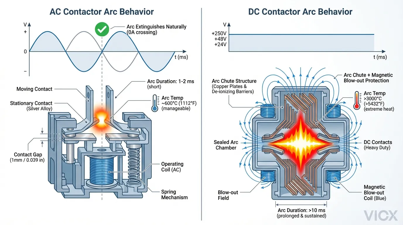
AC Contactors: Alternating Current Applications
AC contactors are optimized for circuits where current alternates direction 50 or 60 times per second (50/60 Hz).
How It Works:
- AC current naturally reaches zero 100–120 times per second (twice per cycle)
- When contacts open, the arc extinguishes automatically at each zero crossing
- Arc suppression is inherently simple—no expensive mechanisms needed
Common AC Voltage Ratings:
- 120V AC (North America, residential)
- 230V AC (Europe, residential)
- 400V AC / 415V AC (Industrial three-phase)
- 480V AC (Industrial North America)
Typical AC Applications:
- HVAC compressors and air handling units
- Lighting control systems
- Electric heaters and resistance loads
- Induction motor starters
- General industrial load switching
DC Contactors: Direct Current Applications
DC contactors handle circuits with unidirectional current flow—electronics never naturally “zero cross.”
Unique Challenge:
- When contacts open, arcs persist indefinitely (no zero crossing to break them)
- Arc becomes a continuous plasma channel, generating extreme heat (>3000°C)
- Heat causes catastrophic contact erosion, coil damage, and fire risk
Advanced Arc Suppression Mechanisms:
- Magnetic blow-out coils: Use magnetic fields to physically extinguish arcs
- Arc chutes: Divide arc into smaller arcs within sealed compartments
- Electronic arc suppression: Diodes or circuits dissipate inductive energy
- Robust contact materials: Silver alloys or tungsten to withstand heat
Common DC Voltage Ratings:
- 12V DC (Automotive, small renewables)
- 24V DC (Industrial control, PLC circuits)
- 48V DC (Solar, battery systems)
- 600V DC (Solar farms, grid-scale storage)
- 800V DC (Modern EV charging systems)
Typical DC Applications:
- Solar photovoltaic (PV) array switching
- Battery energy storage system (BESS) management
- Electric vehicle (EV) charging and onboard systems
- DC industrial processes (electroplating, data centers)
- Renewable energy inverter control
The Catastrophic Consequences of Mismatch
| Scenario | Result | Risk Level |
|---|---|---|
| AC contactor in DC circuit | Arc won’t extinguish; uncontrolled heat; fire | CRITICAL |
| DC contactor in AC circuit | Overengineered, unnecessary cost; works but wasteful | Minor |
| Wrong voltage rating | Arcing at contacts; potential insulation breakdown | CRITICAL |
For a deeper understanding of arc suppression mechanics, see inside AC contactor components and design logic.
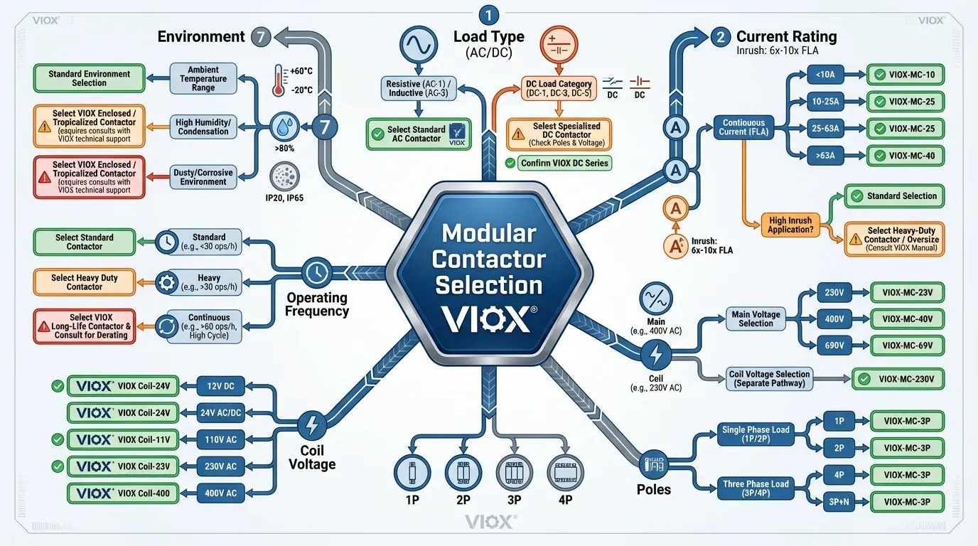
The 7 Essential Selection Criteria for Modular Contactors
1. Load Type and Current Rating (The #1 Mistake: Sizing Errors)
The rated operational current ($I_e$) indicates the maximum current the contactor can safely carry continuously. This is where most engineers make fatal errors.
The Golden Rule: Never use Normal Operating Current alone.
Why? Inrush Current.
When inductive loads (motors, transformers) start, they draw 5–10× their running current for 100–500 milliseconds. Example:
- Motor rated 10A continuous
- Inrush current on startup: 75A (7.5× multiplier)
- Minimum contactor rating needed: 75A (not 10A)
Failure to account for inrush current leads to contact erosion, welding, and coil overheating.
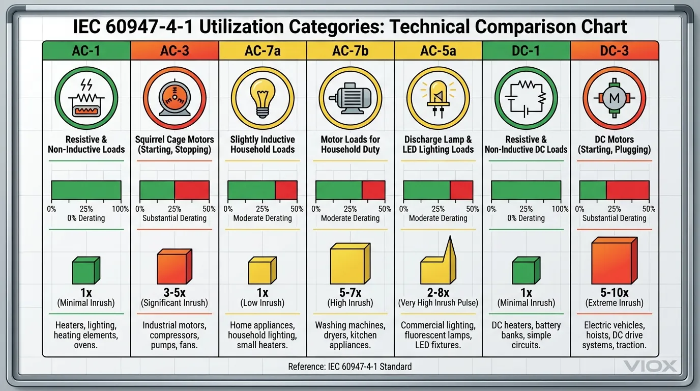
IEC 60947-4-1 Load Categories (Utilization Classes):
The standard defines “utilization categories” that specify switching duty. These categories—AC-1, AC-3, AC-7a, AC-7b, AC-5a, DC-1, DC-3—are fundamental to proper contactor sizing:
| Category | Load Type | Characteristics | Contactor Derating |
|---|---|---|---|
| AC-1 | Resistive (Heaters, Incandescent) | No inrush, stable current | No derating needed |
| AC-7a | Household Resistive | Heaters, ovens, incandescent lighting | ~0% derating |
| AC-7b | Household Motor | Small motors, fans, pumps | ~20–30% derating |
| AC-3 | Industrial Motor (Squirrel-cage) | Motor starting and control | ~30–40% derating |
| AC-5a | LED & Electronic Loads | Capacitive inrush | ~50% derating |
| DC-1 | Resistive DC (Battery heaters) | Stable DC, low inductance ($L/R \leq 1ms$) | No derating |
| DC-3 | DC Shunt Motors | High inductance DC circuits | ~50% derating |
2. Voltage Rating: Both Main Circuit and Coil Voltage
Modular contactors have two independent voltage ratings:
a) Main Circuit Voltage ($U_e$):
- The voltage of the load being switched
- Example: 230V AC, 48V DC, 400V AC
- Rule: Contactor rating must ≥ system voltage
- Undersizing causes insulation breakdown and arcing
b) Control Coil Voltage ($U_c$):
- The voltage that energizes the contactor to close contacts
- Independent from main circuit voltage
- Common coil ratings: 12V, 24V, 110V, 230V (AC or DC)
Example Mismatch:
- You have a 230V AC motor (main circuit)
- Your PLC outputs 24V DC (coil requirement)
- Correct contactor: 230V AC rated, 24V DC coil
Modern Universal Coils:
Some VIOX and premium contactors feature universal coils accepting both AC and DC across wide voltage ranges (e.g., 12–240V AC/DC). Unlike contactors with standard single-voltage coils, universal designs provide:
- Reduced energy consumption (0.5–0.9W holding power)
- Eliminated coil hum and chatter
- Better compatibility with renewable energy systems
Learn more about why contactors have two voltages (control vs. load).
3. Pole Configuration: Controlling Single or Multiple Circuits
The number of poles determines how many independent circuits the contactor can control:
| Poles | Configuration | Typical Application | Common Current |
|---|---|---|---|
| 1P | Single phase conductor | Heating circuits, basic DC | 16–40A |
| 2P | Two conductors; phase + neutral | Single-phase AC, EV chargers | 20–63A |
| 3P | Three conductors (all phases) | Three-phase industrial motors | 25–100A |
| 4P | Three phases + neutral | Medical facilities, critical systems | 25–63A |
Pole Selection Logic:
- Single-phase AC (230V home supply): Use 1P or 2P (2P provides better protection by switching neutral)
- Three-phase AC (industrial 400V): Use 3P minimum; use 4P if neutral must be switched (hospitals, data centers). Learn about understanding 1-pole vs 2-pole AC contactors.
- DC battery systems: Usually 1P or 2P, depending on whether you’re controlling positive, negative, or both
- Solar PV: Commonly 2P (both DC conductors switched for safety)
4. Coil Voltage Matching and Advanced Control Integration
The coil must match your control circuit voltage exactly:
Standard Coil Voltage Options:
- 24V DC (Industrial automation, PLC standard)
- 110V AC (Manual/mechanical control)
- 230V AC (Building automation)
- 12V DC (Automotive, small systems)
Why This Matters:
- Undersized coil → weak magnetic field → incomplete contact closure → arcing
- Oversized coil → wasted energy, heat buildup
- Mismatched voltage → coil burns out within hours
Modern Smart Integration:
VIOX and premium manufacturers now offer contactors with:
- Auxiliary contact blocks (1NO+1NC) for status feedback to PLCs
- Mechanical interlocks preventing simultaneous forward/reverse operation
- Modbus/BACnet interfaces for IoT building automation
- Predictive maintenance sensors monitoring contact wear
For motor-controlled applications, consider how contactors integrate with motor protection circuit breakers for comprehensive load protection.
5. Operating Frequency: Duty Cycle and Electrical Endurance
How often does the contactor switch on and off?
Electrical endurance is specified as “cycles under load.” Manufacturers typically guarantee:
| Duty Class | Switching Frequency | Typical Endurance | Applications |
|---|---|---|---|
| Standard | <50× per day | 100,000–300,000 cycles | HVAC, lighting, general purpose |
| Heavy | 50–500× per day | 500,000–1,000,000 cycles | Industrial pump control, frequent cycling |
| Continuous | >500× per day | 1,000,000+ cycles | LED dimming, power factor correction |
Why It Matters:
Each switching operation causes microscopic contact erosion. After 100,000 cycles:
- Contact resistance increases
- Arcing becomes more pronounced
- Coil heating increases
- Failure is imminent
Cost-Benefit:
- Standard-duty contactor (~$15–30): Fails after ~3 years in heavy-cycle apps
- Heavy-duty contactor (~$25–45): Lasts 7–10 years in the same application
- ROI: <6 months (saved replacement labor + downtime)
6. Environmental Factors: Temperature, Humidity, Dust, Vibration
Ambient Temperature:
- Most modular contactors rated for – 5°C to +60°C standard
- High-temp variant available: – 5°C to +80°C (12% current derating above +40°C); see detailed electrical derating guidance for temperature and altitude
- Enclosed panels with multiple contactors generate +15–20°C additional heat
- Thermal management: Leave 9mm gaps between contactors using spacer modules
IP Protection Ratings (Ingress Protection):
| IP Rating | Protection Level | Suitable Environments |
|---|---|---|
| IP20 | Contact-proof | Dry indoor panels |
| IP40 | Dust resistance | Outdoor enclosures, dusty warehouses |
| IP54 | Dust-sealed, splash resistant | Wet rooms, outdoor areas |
| IP67 | Temporary immersion | Underground/submersible (rare for contactors) |
Humidity & Moisture:
- Contacts corrode when exposed to moisture
- Coil insulation degrades at >85% relative humidity
- Solution: Sealed contactors or DIN rail-mounted contactors inside IP54+ enclosure
Vibration Tolerance:
- High-vibration environments (industrial machinery, vehicles) can cause:
- Loose connections (primary failure mode)
- Incomplete contact closure
- Increased arcing
- Mitigation: Use anti-vibration mounting feet; check torque annually
7. Safety Features and Compliance Standards
Arc Suppression Technology:
- Modern contactors use internal arc chutes or magnetic blow-out coils
- Premium models feature double-break contacts (arc splits into two smaller arcs)
- VIOX BCH8 series includes silent operation technology reducing noise by 60%
Protective Features:
- Manual override: Allows operation during control system failure
- Status indicators: Visual confirmation of contactor state (LED, mechanical flag)
- Thermal overload protection: Integrated or compatible with external relays
- Auxiliary contacts: Feed contactor status back to PLC for diagnostics
Compliance Standards (Critical for North America & Europe):
| Standard | Application | Key Requirements |
|---|---|---|
| IEC 61095 | Household/residential | Basic safety, insulation, operating cycles |
| IEC 60947-4-1 | Industrial modular contactors | Load categories, arc suppression, thermal limits |
| UL 508 | North American industrial panels | Breaking capacity, thermal limits |
| EN 45545-2 | Railway systems | Fire safety, smoke emission |
| ISO 13849-1 | Safety-critical applications | Forcibly-guided contacts, redundancy |
For detailed understanding of IEC load classification, refer to the IEC 60947-3 utilization categories guide and learn how contactors vs relays differ in safety-critical systems.
Step-by-Step Decision Framework: The 6-Step Selection Process
Step 1: Identify Your Load Type (AC or DC)
Answer this question: Is your load powered by alternating current or direct current?
AC Loads: Home/commercial power grids, three-phase industrial equipment, HVAC systems
DC Loads: Solar panels, battery systems, electric vehicles, renewable energy inverters, data center power distribution
→ If uncertain, measure voltage with a multimeter:
- AC voltage fluctuates continuously (50/60 Hz)
- DC voltage reads steady
Step 2: Calculate Current Requirements (Including Inrush)
Step 2a: Find Normal Operating Current (FLA)
For equipment with nameplate rating:
- Read FLA directly from equipment label
- Example: Motor nameplate shows “10A FLA”
For three-phase AC motors (if not labeled):
Where:
- $P$ = Power in kW
- $U$ = Voltage (Volts)
- $\cos(\phi)$ = Power factor (typically 0.85–0.95 for motors)
- $\eta$ = Efficiency (typically 0.85–0.92 for motors)
Step 2b: Estimate Inrush Current
| Load Type | Inrush Multiplier | Example |
|---|---|---|
| Resistive (heaters) | 1–1.5× | 10A load = 10A inrush |
| Incandescent lighting | 1–2× | 10A load = 10–20A inrush |
| Motor (soft start) | 3–5× | 10A load = 30–50A inrush |
| Motor (direct on-line) | 5–10× | 10A load = 50–100A inrush |
| LED driver/electronics | 2–8× | 10A load = 20–80A inrush |
| Transformer | 8–12× | 1A load = 8–12A inrush |
Step 2c: Apply Load Category Derating
Refer to the table in Section “Load Type and Current Rating” above.
Step 3: Confirm Voltage Requirements
Record both:
- Main circuit voltage (load being switched): e.g., 230V AC, 48V DC
- Control coil voltage (PLC or control system output): e.g., 24V DC, 110V AC
Verify contactor datasheet specifies both ratings.
Step 4: Choose Pole Configuration
Decision Tree:
Is load single-phase or three-phase?
├─ Single-phase AC → Choose 1P or 2P (2P recommended for safety)
├─ Three-phase AC → Choose 3P (minimum) or 4P (if neutral switching required)
└─ DC (any power) → Choose 1P or 2P depending on circuit switching requirement

Must both positive AND negative be switched?
├─ Yes → Choose 2P (both poles switching)
└─ No → Choose 1P (single pole sufficient)
Step 5: Assess Operating Environment and Duty Cycle
Checklist:
- Ambient temperature range: ___°C to ___°C
- Humidity: Dry / Damp / Wet environment?
- Dust/contamination level: None / Light / Heavy?
- Vibration environment: None / Moderate / High?
- Switching frequency: ___ times per day
- Need for noise control? Yes / No
- Space available in panel: ___ mm
Implications:
- High temperature → Select heavy-duty, derating required
- High humidity → Sealed contactor or IP54+ enclosure
- High vibration → Anti-vibration mounting
- Frequent switching → Heavy-duty or solid-state contactor
- Noise-sensitive area → Solid-state or “silent type” contactor
Step 6: Review Special Requirements
Additional Features to Consider:
- Auxiliary contact blocks (for PLC feedback)
- Mechanical interlock (for reversing applications)
- Integrated thermal overload relay
- Smart/IoT monitoring capability
- Manual override for emergency operation
- Specific certification (UL, CE, CSA)
Contactor Selection Comparison Table: Quick Reference
Use this table to quickly cross-reference your application:
| Application | Load Type | Recommended Voltage | Poles | Current Range | Duty | Special Notes |
|---|---|---|---|---|---|---|
| HVAC Compressor | AC-3 Motor | 230V/400V AC | 3P | 15–40A | Heavy | Include soft-start for inrush |
| Home EV Charger | AC-1/AC-7a | 230V AC | 2P | 16–32A | Standard | Coil: 24V DC recommended |
| Solar PV Array Switch | DC-1 | 600V DC | 2P | 20–63A | Standard | Arc suppression critical |
| Industrial Lighting | AC-7a | 230V/400V AC | 1P–3P | 16–63A | Heavy | Multiple zones → multiple contactors |
| Pool Pump | AC-3 Motor | 230V AC | 1P | 10–16A | Standard | 1.5× inrush factor; see star-delta starter wiring for soft-start options |
| Data Center PDU | AC-1 | 400V AC | 3P | 63–100A | Heavy | Modbus integration recommended |
| EV Battery Disconnect | DC-3 Motor | 48–800V DC | 2P | 50–200A | Standard | Specialized arc suppression required |
| Smart Home Relay | AC-7a | 230V AC | 1P | 10–20A | Standard | Universal coil preferred (noise reduction) |
Real-World Application Examples: From Theory to Practice
Example 1: Three-Phase Industrial HVAC System
Scenario:
You’re installing a new air handling unit for a 5-story office building. The motor nameplate shows:
- Power: 7.5 kW
- Voltage: 400V three-phase AC
- FLA: 15A
- Starting method: Direct on-line (DOL)
Your Decisions:
- Load Type: AC-3 (induction motor)
- Inrush Current: 15A × 7 = 105A (DOL starting)
- Contactor Rating: Minimum 105A → Select 125A contactor
- Main Circuit Voltage: 400V AC ✓
- Coil Voltage: Building has 24V DC PLC → Specify 24V DC coil
- Poles: Three-phase → 3P configuration
- Duty Cycle: HVAC cycles 3–5× per day → Standard duty acceptable
- Environment: Indoor, air-conditioned space, no dust/moisture
Recommended Contactor:
- Type: AC contactor, 125A, 400V AC, 3P, 24V DC coil
- Example: VIOX BCH8-63/40 (63A AC-3 rated = ~110A effective capacity)
- Auxiliary contacts: 1NO+1NC for status feedback to BMS
Example 2: Residential Solar Battery System
Scenario:
You’re designing a 48V DC battery backup system for a home with 10kWh storage. Battery disconnect contactor must:
- Control 48V DC from battery bank to inverter
- Handle 200A continuous charge/discharge current
- Include status LED to show connection state
- Meet safety code requirements
Your Decisions:
- Load Type: DC-1 (resistive) / DC-3 (motor if pump loads present)
- Continuous Current: 200A
- Contactor Rating: 200A × 1.25 safety factor = 250A minimum
- Main Circuit Voltage: 48V DC ✓
- Coil Voltage: Inverter provides 24V DC signal → Specify 24V DC coil
- Poles: Both (+) and (–) conductors must disconnect → 2P configuration
- Duty Cycle: Low-frequency switching (once daily) → Standard duty acceptable
- Arc Suppression: CRITICAL – DC requires robust arc suppression (magnetic blowout or arc chutes)
Recommended Contactor:
- Type: DC contactor, 250A, 48V DC, 2P, 24V DC coil, robust arc suppression
- Example: VIOX specialized DC contactor with magnetic blow-out coil
- Auxiliary contacts: Status feedback to home automation system
- For further guidance on selecting contactors by motor power, see how to select contactors and circuit breakers based on motor power
Example 3: LED Lighting Control in Modern Office
Scenario:
A 50-desk open office needs automated lighting control (motion-activated). Each lighting zone draws 5A from 230V AC. Silence requirement: <20dB (no audible hum from contactors).
Challenge: LED drivers have massive capacitive inrush (5–8× load current).
Your Decisions:
- Load Type: AC-5a (LED electronic load)
- Continuous Current: 5A per zone
- Inrush Current: 5A × 7 = 35A (capacitive inrush)
- Contactor Rating: 35A minimum → Select 40–50A (derating for AC-5a)
- Main Circuit Voltage: 230V AC ✓
- Coil Voltage: Motion sensor outputs 12V DC → Specify universal 12–240V AC/DC coil (eliminates hum)
- Poles: Single phase → 1P or 2P (2P for neutral switching)
- Noise Control: Solid-state contactor or “Silent Type” electromagnetic contactor required
- Switching Frequency: High (10–20× per day) → Heavy-duty rating preferred
Recommended Contactor:
- Type: AC silent-type contactor, 40A, 230V AC, 1P, universal coil
- Alternative: Solid-state AC contactor (zero-crossing technology, completely silent)
- Auxiliary contacts: 1NC for feedback to motion sensor controller
Common Selection Mistakes and How to Avoid Them
| Mistake | Consequence | Prevention |
|---|---|---|
| Using AC contactor for DC | Uncontrolled arc, fire, equipment damage | ALWAYS verify load type before ordering |
| Undersizing for inrush current | Contact welding, coil burnout, panel fire | Factor in 5–10× multiplier for motors |
| Ignoring environmental temperature | Premature coil failure, reduced contact life | Check ambient temperature; apply derating |
| Mismatched coil voltage | Weak magnetic field, incomplete closure, arcing | Verify PLC/control signal voltage matches coil |
| No auxiliary contacts | No feedback to control system, diagnostics impossible | Specify auxiliary contacts for all critical circuits |
| Insufficient pole count | Neutral unprotected in single-phase AC | Use 2P minimum for residential AC |
| Ignoring duty cycle | Premature failure in high-cycle applications | Choose heavy-duty for >100 cycles/day |
| No thermal spacing on DIN rail | Cumulative heat causes derating, failures | Leave 9mm gaps between high-current contactors |
Installation, Maintenance, and Commissioning Best Practices

Proper installation is critical. For comprehensive guidance on inspection and maintenance, refer to the industrial contactor maintenance and inspection checklist.
Pre-Installation Checklist
- Verify contactor specifications match design (voltage, current, poles, coil)
- Confirm DIN rail has adequate space (18–36mm per unit + thermal spacing)
- Check that all control wiring is pre-routed and labeled
- Ensure circuit breaker upstream of contactor is properly rated
- Verify environmental conditions (temperature, humidity, dust)
- Confirm all personnel are qualified and PPE-equipped
Installation Steps
- Mount on DIN Rail: Snap contactor onto 35mm DIN rail (IEC 60715)
- Verify Orientation: Contact terminals face downward; coil terminals accessible
- Leave Thermal Spacing: 9mm gap to adjacent components (use spacer modules for contactors >20A)
- Main Circuit Wiring:
- Use copper conductors per circuit current rating
- Apply recommended torque (see torque table below)
- Double-check polarity for DC circuits
- Control Circuit Wiring:
- Twist low-voltage control wires to minimize EMI
- Keep away from high-current conductors
- Confirm coil voltage matches supply exactly
- Auxiliary Contacts (if equipped):
- Wire to PLC/monitoring system for status feedback
- Test with multimeter before energizing
Terminal Torque Specifications
| Current Rating | Wire Size (mm²) | Torque (N·m) | Torque (in-lb) |
|---|---|---|---|
| 16A | 1.5–2.5 | 0.5 | 4.4 |
| 20A | 2.5–4 | 0.8 | 7 |
| 25A | 4–6 | 0.8 | 7 |
| 32A | 6–10 | 1.5 | 13 |
| 40A | 10–16 | 2 | 18 |
| 63A | 16–25 | 3.5 | 31 |
| 100A | 35–50 | 6 | 53 |
Critical: Under-torqued connections are the #1 cause of contactor failures and panel fires. Always use a calibrated torque screwdriver.
Commissioning Tests
- Coil Resistance Test:
- Measure with multimeter across coil terminals
- Expected: 5–20 ohms (typical 230V coil)
- Below 5Ω → Coil shorted, replace immediately
- Contact Continuity Test:
- Main contacts closed (de-energized) → Should read 0.1–0.5Ω
- Indicates good contact pressure and low resistance
- Above 1Ω → Clean contacts or investigate
- Voltage Drop Test:
- With rated load current flowing → Measure voltage drop across closed contacts
- Typical: <100mV at rated current
- Above 200mV → Contact deterioration detected
- Coil Energization Test:
- Energize coil with rated voltage
- Listen for distinctive “click” (contacts closing)
- Measure voltage at coil terminals (should match supply ±10%)
For detailed testing procedures, refer to how to test a contactor with a skill-based guide. For troubleshooting common problems, see the contactor troubleshooting guide for buzzing, coil failure, and no-click issues.
Maintenance Schedule
| Interval | Action | Purpose |
|---|---|---|
| Monthly | Visual inspection | Detect arcing scars, corrosion, loose wires |
| Quarterly | Thermal imaging (IR camera) | Identify hotspots indicating poor connections |
| Semi-annually | Contact resistance measurement | Detect contact degradation early |
| Annually | Torque verification | Ensure connections remain tight |
| Biennially | Full replacement if in heavy-duty service | Preventive maintenance before failure |
FAQ: 10 Questions Engineers Ask When Choosing Modular Contactors
Q1: Can I use a DC contactor in an AC circuit?
A: Technically yes, but it’s wasteful. A 48V DC-rated contactor would work in a 230V AC circuit (AC has zero-crossings helping arc extinction), but you’d pay 2–3× the cost for capabilities you don’t need. Use AC contactors for AC applications.
Q2: What’s the difference between rated current and breaking capacity?
A: Rated current is the maximum continuous current the contactor carries (e.g., 63A). Breaking capacity is the maximum current it can safely interrupt (e.g., 6kA). Breaking capacity is critical for protection against short circuits. Always verify both ratings.
Q3: Do I need auxiliary contacts?
A: Yes, for any critical or networked system. Auxiliary contacts provide:
- Status feedback to PLC/BMS (confirmation contactor closed)
- Diagnostic data (helps troubleshoot failures)
- Interlocking (safety for reversing applications)
- Cost: +$5–10 per unit; Value: Prevents catastrophic failures
Q4: What causes contactor coil failure?
A: Top 3 causes:
- Voltage mismatch (e.g., supplying 12V to 24V coil)
- Overheating (inadequate thermal spacing, ambient temp too high)
- Moisture ingress (condensation in humid environments)
Mitigation: Verify voltage, maintain thermal spacing, use sealed contactors in damp environments.
Q5: How long do modular contactors typically last?
A: Under normal conditions:
- Standard-duty electromagnetic: 5–8 years (~100,000 cycles)
- Heavy-duty electromagnetic: 8–12 years (~500,000–1,000,000 cycles)
- Solid-state: 10–15 years (no mechanical wear; limited by capacitors)
Life depends heavily on load type, frequency, and environment.
Q6: What’s “silent type” or “hum-free” contactor?
A: Contactors using AC coils produce a 50/60Hz “hum” from vibrating magnetic circuits. “Silent types” use:
- Electronic coils (powered by internal rectifier) → eliminates hum
- Magnetic damping systems → absorbs vibration noise
- Typically reduces noise by 60% (from ~40dB to <20dB)
Essential for offices, hospitals, residences.
Q7: Can I parallel multiple contactors for higher current capacity?
A: Strongly discouraged. When contactors are in parallel, minor differences in contact resistance can cause unequal current distribution, leading to overheating and failure of the lower-resistance unit. Instead, select a single contactor with adequate rating.
Q8: What’s the difference between modular and traditional (bolt-on) contactors?
A:
- Modular: DIN rail mounted, 18–36mm width, compact, residential/commercial standard. Learn more by comparing modular contactors versus traditional contactors.
- Bolt-on: Larger, panel-mounted with bolts/studs, 100–200A+, industrial/utility grade
Modular is preferred for modern distribution boards; bolt-on is reserved for massive power applications.
Q9: How do I handle thermal derating at high ambient temperatures?
A: Above 40°C ambient:
- Derating factor typically 2–3% per °C above 40°C
- Example: 63A contactor at 60°C ambient → 63A × (1 – 0.02 × 20) = 63A × 0.6 = 37.8A effective rating
Solution: Oversize contactor or improve ventilation (forced cooling fans, larger enclosure).
Q10: What’s the difference between IEC and UL standards?
A:
- IEC 61095 (Europe/global): Defines household modular contactors; less demanding than UL
- UL 508 (North America): Defines industrial control equipment; stricter breaking capacity and thermal requirements
- IEC 60947-4-1 (Global industrial): Modular and industrial contactors; defines load categories
Always verify your region’s requirements; North American panels require UL certification.
Key Takeaways: The 10-Point Master Checklist
- 1. Match Load Type First: AC or DC—this is THE critical decision. One mistake can cause fires.
- 2. Factor Inrush Current: Never size based on running current alone. Motors can draw 5–10× their FLA on startup.
- 3. Verify Both Voltages: Main circuit voltage AND coil voltage must match specifications.
- 4. Use IEC Load Categories: Reference AC-1, AC-3, AC-7a, DC-1, DC-3 to apply proper derating factors.
- 5. Choose Correct Poles: 1P for simple circuits; 2P for single-phase safety; 3P for three-phase; 4P for critical neutral switching.
- 6. Include Auxiliary Contacts: Status feedback prevents undiagnosed failures and enables smart integration.
- 7. Plan for Thermal Spacing: Leave 9mm gaps between high-current contactors to prevent cumulative overheating.
- 8. Match Duty to Application: Standard duty for occasional switching; heavy-duty for frequent cycling; solid-state for silent/high-frequency requirements.
- 9. Specify Certification: Ensure compliance with regional standards (IEC, UL, CE, CSA).
- 10. Invest in Proper Installation & Testing: Under-torqued connections are the #1 cause of panel fires. Use calibrated tools and commission before load.
Conclusion: From Confusion to Confidence
Choosing the right modular contactor is no longer guesswork. By working through this systematic 6-step selection framework—identifying load type, calculating current requirements, confirming voltages, choosing poles, assessing environment, and reviewing special needs—you can confidently select a contactor that will operate safely and reliably for years to come.
The consequences of poor selection are severe: fires, equipment damage, costly downtime, safety liability. But armed with this guide’s principles, standards references (IEC 60947-4-1, IEC 61095), and VIOX’s engineering expertise, you’re now equipped to avoid the common pitfalls that trip up even experienced engineers.
