

On this page
A contactor can meet the motor’s normal switching requirement and still be damaged when a short circuit occurs. The missing question is not simply whether the breaker can interrupt the fault. It is what condition the starter is permitted to be in afterward.
Short Answer
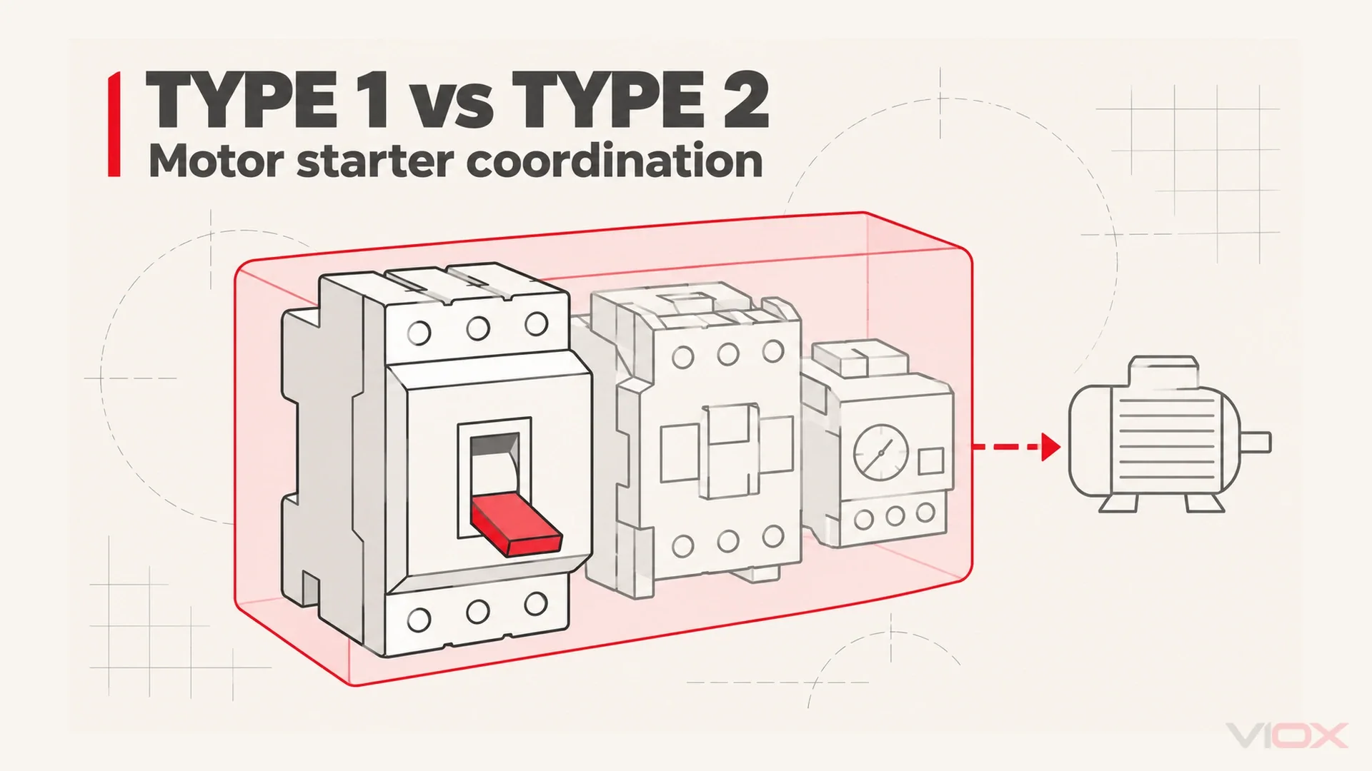
A contactor and separate thermal overload relay do not provide short-circuit interruption by themselves. Their post-fault condition depends on the specified short-circuit protective device (SCPD) and the coordination demonstrated for the complete combination. Type 1 permits damage requiring repair or replacement; Type 2 requires suitability for further use, while recognizing limited, easily separable contact welding under the manufacturer’s instructions. Contactor rated current alone cannot establish either result.
Here, coordination means the starter coordination type in IEC 60947-4-1, not breaker selectivity and coordination. Selectivity concerns which protective device operates; this article concerns what remains serviceable after the fault is cleared.
The title’s “breaker” refers to the front-end protective role. A suitable fuse can also be the SCPD. Neither a breaker nor a contactor earns the whole assembly a coordination type in isolation. If the equipment boundary is unclear, start with contactor versus motor starter.
What Happens Before the Short Circuit Is Cleared?
In a conventional starter circuit, the devices perform different jobs:
- SCPD: interrupts the short circuit and limits the downstream stress according to its actual protective characteristics.
- Contactor: switches the motor during normal operation within its declared duty; it is not a substitute for the SCPD. See what a contactor does.
- Thermal overload relay: detects sustained overload and initiates opening through the control system; its power-circuit elements still carry the motor current. See thermal overload relay operation.
The SCPD clears the fault on a millisecond timescale; before it does, fault current has already passed through the contactor and overload relay.
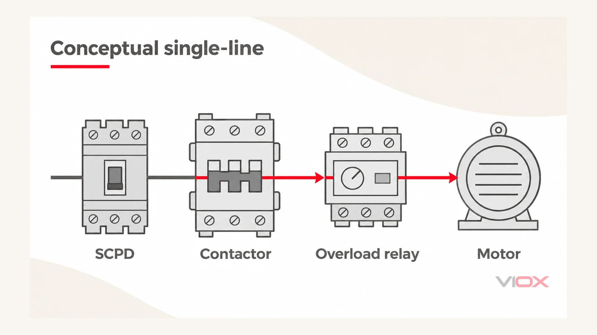
That current produces heating in the conducting path and electrodynamic forces in the contact assembly. Contact pressure can be overcome, contact surfaces can separate and arc, and local heating can cause contact welding. The relay’s current-carrying elements also face thermal and mechanical stress.
A successful interruption therefore answers only part of the engineering question. The protective device may have cleared the circuit while the contactor or overload relay no longer meets its service requirements. Coordination defines the accepted post-test outcome for the specified combination.
Type 1 vs Type 2 Coordination Under IEC 60947-4-1
IEC 60947-4-1 is the standard anchor for the contactor and motor-starter coordination types discussed here. The following is a conceptual explanation, not a substitute for the full standard or a declaration for a particular product combination.
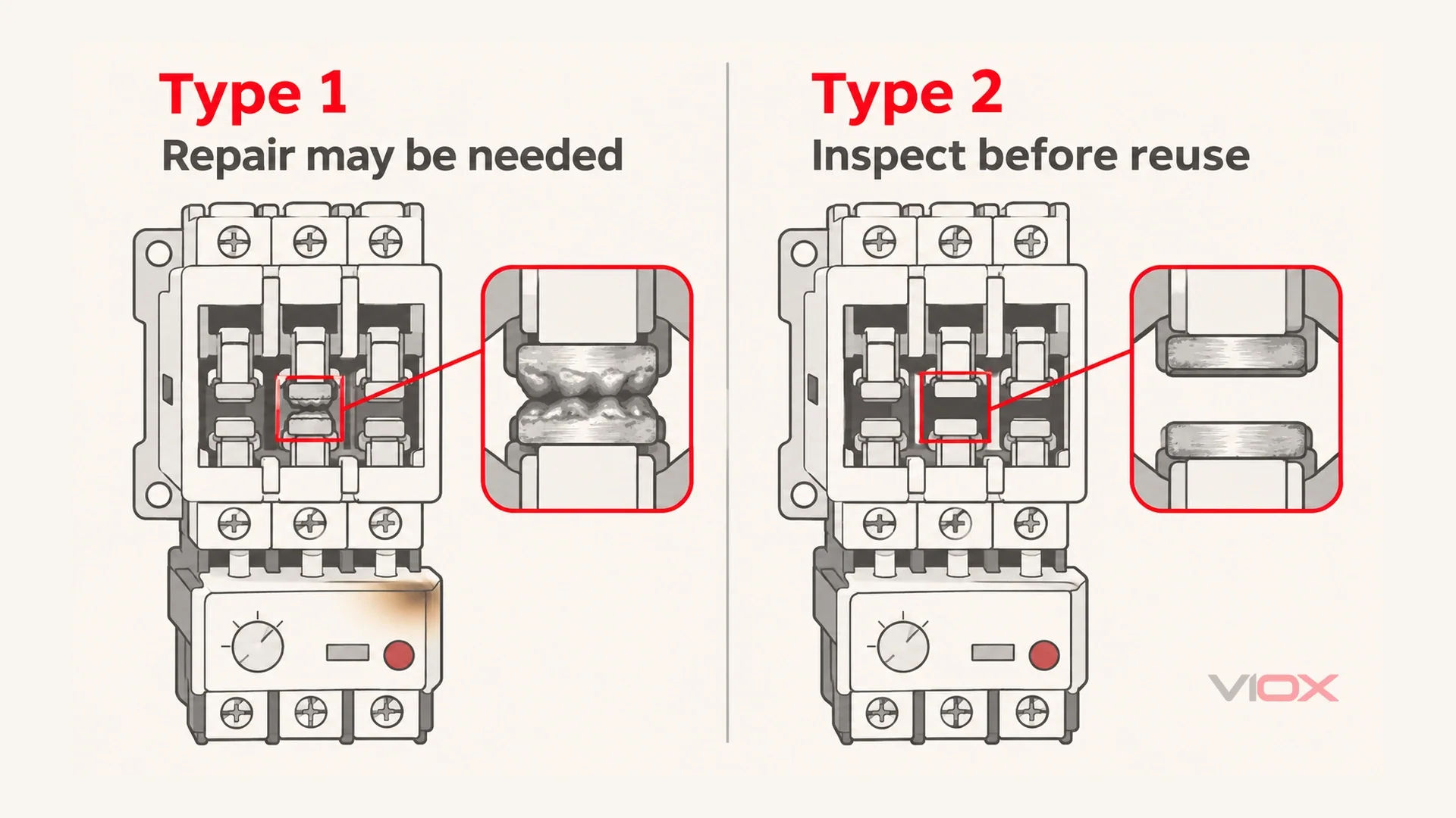
Type 1: repair or replacement can be necessary
Under short-circuit conditions, the contactor or starter must not cause danger to persons or the installation. It may nevertheless be unsuitable for further service without repair or replacement of parts.
Contact welding and damage to the overload relay can therefore be consistent with Type 1 performance. This is permission for a bounded damage outcome under the test criteria, not permission for injury, hazardous exposed parts or damage to the surrounding installation.
Type 1 does not mean “the starter must fail.” It means continued service without repair is not the promised outcome. The actual condition still needs assessment after a fault.
Type 2: suitability for further use is required
Type 2 retains the no-danger requirement and adds suitability for further use after the short-circuit event. The possibility of contact welding is recognized, but permitted welding must be readily separable without significant deformation, following the manufacturer’s maintenance instructions. Damage to the overload relay is not an accepted outcome, and its overload-protection characteristics must be retained.
This is a more demanding recovery requirement, not a guarantee that the contacts can never weld. It also does not authorize immediate re-energization. The fault must be corrected, the equipment isolated and inspected, and the manufacturer’s required checks completed before return to service.
| Post-fault question | Type 1 coordination | Type 2 coordination |
|---|---|---|
| Can the starter remain in service? | Repair or replacement may be needed before further service. | It must remain suitable for further use under the verified conditions. |
| What about main contacts? | Welding or damage can require replacement. | Limited welding is permissible only when readily separable under the manufacturer’s conditions. |
| What about the overload relay? | Damage may be permissible within the test’s safety requirements. | The relay must remain undamaged and retain its overload-protection characteristics. |
| How is operation restored? | Assess, repair or replace as necessary, then verify the installation. | Correct the fault and complete the specified inspection and maintenance before release. |
| What do both require? | No danger to persons or the installation. | No danger to persons or the installation. |
What Actually Protects the Contactor? The SCPD
The SCPD determines how the short-circuit current is interrupted and what stress reaches the downstream devices. For comparable fault conditions, stronger current limitation and reduced clearing exposure can reduce the thermal and electrodynamic duty imposed on the starter.
Let-through energy, often expressed as I²t, describes part of the thermal exposure. Peak let-through current matters to mechanical stress. Neither quantity, considered alone, demonstrates the complete post-fault performance required for Type 2 coordination.
This explains a counterintuitive selection result: manufacturer-published coordination tables can require different contactor sizes for the same motor when the front-end SCPD changes, potentially several frame sizes apart. The motor’s normal demand has not changed; the verified short-circuit stress and the combination’s required outcome have.
Likewise, a breaker that remains serviceable while the contactor contacts weld is not, by itself, evidence of poor contactor quality. That condition may be consistent with the declared Type 1 result. Check the actual coordination claim, installation conditions and damage before deciding whether the event met the specification. Type 1 is not a blanket explanation for every failure.
Why a Coordination Table Cannot Be Calculated or Generalized
A starter coordination table summarizes tested combinations and their declared conditions. It is not a formula that converts a contactor’s rated current into a Type 2 claim. Verification concerns the SCPD, contactor, overload protection and applicable installation arrangement together.
The conditional short-circuit current, commonly identified as Iq in coordination information, belongs to those specified conditions. Read the manufacturer’s exact terminology and table notes. It is not an independent short-circuit interrupting rating of the contactor, nor can the breaker’s own breaking capacity replace it.
Three restrictions follow:
- A changed component needs renewed verification. Replacing any member of the combination invalidates reliance on the original entry unless the manufacturer explicitly includes that alternative. A different breaker in the same brand is still a different protective characteristic unless covered.
- Voltage and fault duty must be covered. The declared voltage and Iq must cover the installation conditions. If the prospective short-circuit current exceeds the declared Iq, that entry does not establish the required result. Do not assume an unlisted voltage or extrapolate beyond the published conditions.
- Individual compliance does not prove combination performance. A breaker, contactor and relay can each satisfy their own requirements without forming a verified Type 2 starter. An unsupported mixed-brand assembly cannot inherit a rating by adding together its component certificates.
Calculations and protective-device curves can support engineering assessment. They cannot replace the combination evidence needed to declare a coordination type. The table’s accessories, settings, mounting and connection conditions also matter; keeping only its headline device names is insufficient.
How to Select a Verified Combination
Establish the appropriate starter architecture using the motor starter types guide, then apply the short-circuit coordination checks below.
Step 1: establish prospective fault current and circuit voltage
Obtain the prospective short-circuit current at the installation point from the applicable system study or verified design information. Record the operating voltage as well. Do not substitute a motor nameplate current or the breaker’s marked interrupting capacity for the site’s available fault current.
Step 2: choose the required recovery outcome
Where interruption and repair would have serious operational consequences, specify Type 2 and a documented inspection-and-restoration process. Where planned repair after a fault is acceptable, Type 1 may meet the requirement.
The decision follows the consequence of losing the load, rather than a circuit name. Type 2 improves the specified starter recovery outcome; it does not guarantee uninterrupted production, a healthy motor or the elimination of the original fault.
Step 3: select the complete entry from one manufacturer’s table
Use one manufacturer’s published coordination table as the authority for the complete listed combination. Identify the exact SCPD, contactor, overload relay and coordination type. Check the voltage, declared Iq, settings and every applicable note against the installation.
Do not mix separate tables or assemble a new row from similarly rated devices. A shared brand name is not sufficient either: the exact combination must be covered. Retain the document revision with the project record so a later replacement can be checked against the same basis.
Step 4: recheck normal motor duty separately
Confirm that the overload relay’s setting range covers the motor’s full-load current and that the contactor’s applicable AC-3 rating meets the normal switching duty. Coordination does not replace those checks.
For the normal-duty sizing process, use motor starter sizing. That guide addresses the components needed for normal operation; this article addresses the verified condition after a short circuit.
Step 5: resolve missing evidence before declaring a type
Ask the manufacturer for the proposed combination’s coordination table or supporting test evidence. State the voltage, prospective fault current, required type, component identities and installation arrangement. A request for “a bigger contactor” does not identify the missing evidence.
Alternative paths include an already verified fuse-protected combination or a documented MPCB-based combination starter; neither architecture automatically proves Type 2. With a fuse-protected arrangement, replace an operated fuse-link as instructed after fault clearance and complete the starter checks. See thermal overload relay versus MPCB for the functional distinction.
Control and protective switching devices (CPS), covered separately by IEC 60947-6-2, are another equipment category whose declared performance must be checked rather than assumed equivalent to a discrete starter.
Until the required evidence is available, record the coordination type as unverified. Do not replace a missing test record with a calculated claim.
Five Common Coordination Mistakes
- Selecting the contactor only from motor current. This addresses part of normal duty but leaves the short-circuit outcome unspecified.
- Increasing the contactor by one size and calling it Type 2. Additional material or a larger frame does not demonstrate the required combination performance.
- Treating every welded contact under Type 1 as a quality complaint. Compare the observed result with the declared conditions before assigning a cause or responsibility.
- Using the wrong voltage or Iq entry. A valid row for another condition does not cover the installation merely because the device names look familiar.
- Combining three manufacturers’ devices and asserting Type 2. Component compliance and nominal ratings do not provide evidence for that unverified assembly.
Frequently Asked Questions
Does Type 2 coordination mean the contacts never weld?
No. Limited welding is recognized if the contacts can be readily separated under the manufacturer’s specified conditions without significant deformation. The starter must remain suitable for further use after the required checks.
Can Type 1 equipment be switched straight back on after a short circuit?
No such permission follows from Type 1. Isolate the equipment, correct the fault and assess the starter. Repair or replacement may be required before inspection and authorized return to service.
Why cannot a coordination table be transferred across brands?
Its evidence applies to the specified devices and conditions. Changing a component creates a combination that the original entry does not cover unless the manufacturer expressly includes it; individual device compliance is insufficient.
Can I calculate Type 2 coordination when no table is available?
Calculations can inform an assessment, but they cannot establish the tested post-fault outcome. Obtain the manufacturer’s combination evidence or select a different arrangement with documented performance.
What changes when a fuse is the SCPD?
The specified fuse and its protective characteristics become part of the verified combination. A fuse-protected starter still needs the appropriate table; after fault clearance, replace the operated fuse-link as instructed, as well as completing the starter checks.
Choose for the verified post-fault outcome, not just the contactor’s normal current: when reviewing AC contactors and thermal overload relays, request the manufacturer’s coordination table and select the complete documented combination.