On this page
A fuse holder is not selected by current rating or physical fit alone. Choose the fuse-link and fuse system first, then verify that the holder accepts the exact fuse dimensions and contact format, is rated for the system voltage and AC/DC duty, carries the circuit current under the actual thermal conditions, matches the mounting and conductor arrangement, and provides the required touch and environmental protection.
A basic fuse holder is also not automatically a load-break switch or an isolator. If personnel must operate the device under load or use it as a defined isolation point, specify equipment with that function and the corresponding rating.
Fuse Holder Types at a Glance
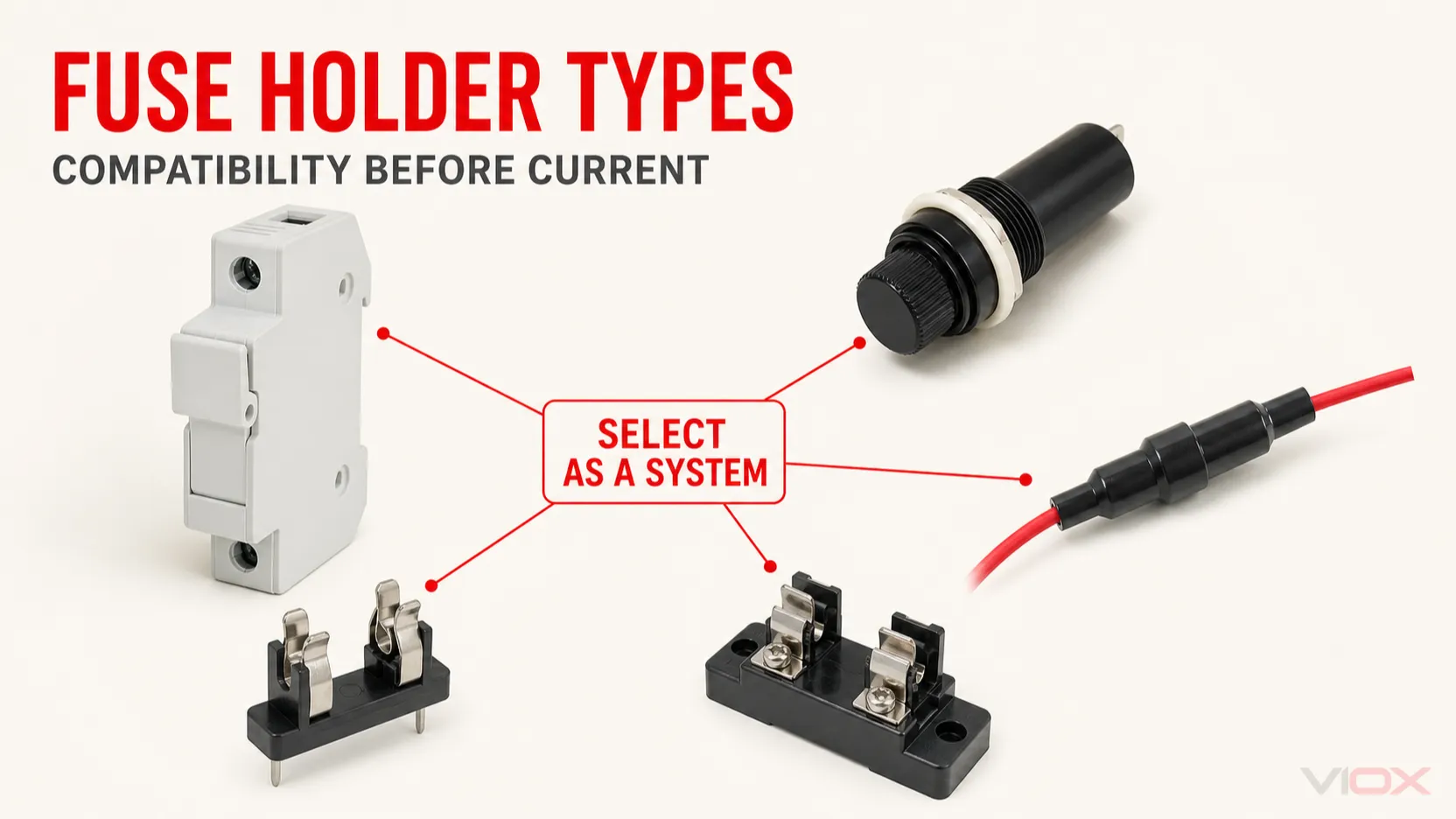
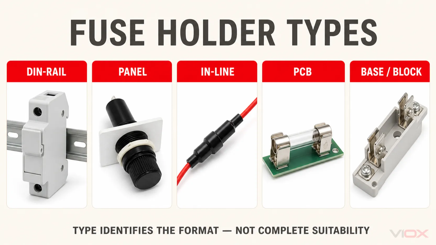
The most useful way to classify fuse holders is by how they are mounted and serviced.
| Fuse holder type | Best suited to | Main advantage | Critical checks |
|---|---|---|---|
| DIN-rail modular holder | Control panels, distribution boards, PV and industrial cabinets | Modular installation and front access | Fuse format, poles, AC/DC rating, terminal capacity, heat rise, touch safety |
| Panel-mount holder | Equipment with a replaceable fuse accessible from an enclosure wall | Fuse replacement without opening the equipment | Panel cutout, rear terminal protection, cap/carrier retention, IP rating |
| In-line holder | Cable harnesses, localized protection, mobile and retrofit circuits | No PCB or panel space required | Wire size, termination method, strain relief, sealing, fuse format |
| PCB holder or fuse clips | Power supplies, controllers and electronic assemblies | Compact, direct board integration | Footprint, solder process, creepage/clearance, heat around the fuse |
| Fuse base or fuse block | Industrial power distribution and higher-current fuse systems | Robust mounting and conductor termination | Exact fuse system, contact arrangement, conductor size, barriers and safe service method |
This table identifies the mechanical family only. It does not prove that a holder is suitable for a particular circuit.
What a Fuse Holder Does
A fuse holder provides the mechanical support, electrical contacts, terminals and, where applicable, a carrier or cover for a replaceable fuse-link. During normal operation, the complete current path includes the conductors, terminals, holder contacts and fuse-link. Every connection contributes resistance and heat.
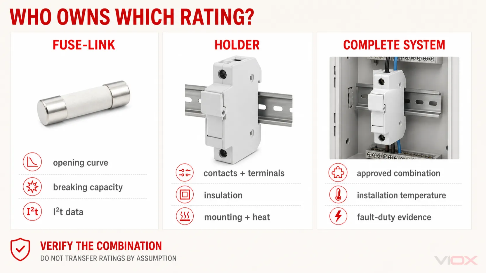
When the fuse-link operates, it interrupts the overcurrent. The holder must remain suitable for the electrical, thermal and mechanical stresses assigned to it, but the holder does not replace the fuse-link’s time-current characteristic, utilization category, breaking-capacity evidence or energy-limiting data.
For a deeper explanation of the current path and components, see How Does a Fuse Holder Work?.
Fuse Holder, Fuse Block, Fuse Carrier and Fuse Base
These terms are not perfectly uniform across every market or manufacturer:
- Fuse holder is the broad term for an assembly that accepts and connects a fuse-link.
- Fuse base is the fixed portion mounted to a panel, rail or structure.
- Fuse carrier is the removable part that holds the fuse-link in some systems.
- Fuse block commonly describes an open or enclosed base with one or more fuse positions, but it is not universally limited to multiple fuses.
- Fuse clips are open contacts that retain a cartridge fuse, often on a printed circuit board (PCB).
The fuse-link is the replaceable protective element. For the terminology boundary, read Fuse vs Fuse Link: What Is the Difference?.
A Holder Is Not Necessarily a Switch-Disconnector
Removing a carrier or pulling a fuse can expose personnel and equipment to an arc or energized parts if the circuit is still carrying current. A holder may be finger-safe or withdrawable yet still lack a load-break rating.
If the application requires routine switching, visible isolation, interlocking or lockout/tagout, verify a defined disconnecting function rather than inferring it from appearance. The decision is covered in Fuse Holder vs Fuse Switch Disconnector.
Five Main Types of Fuse Holders
1. DIN-Rail Modular Fuse Holders
DIN-rail holders are common in industrial control panels, distribution assemblies, automation cabinets and photovoltaic (PV) combiner boxes. Their modular form supports consistent panel layout, and many designs provide front access, multi-pole configurations or status indication.
They are not interchangeable simply because they occupy the same DIN-rail width. Check:
- exact fuse-link dimensions and contact system;
- rated operational voltage and explicit AC or DC suitability;
- number of poles and whether all required conductors are protected or disconnected;
- terminal conductor range, preparation and tightening instructions;
- permissible power dissipation or temperature-rise conditions;
- touch protection with the carrier inserted and, where specified, removed;
- indication circuit behavior and leakage, if an indicator is fitted.
For PV applications, confirm that the fuse-link, holder and assembly are intended for the DC system voltage and prospective fault conditions. A generic AC modular holder is not made suitable for PV merely by installing a PV fuse-link.
2. Panel-Mount Fuse Holders
Panel-mount holders pass through an enclosure wall and typically allow a cartridge fuse to be replaced from the front. They are useful in instruments, power supplies, machinery and equipment that should remain closed during normal fuse replacement.
Selection depends on more than the cartridge size. Verify the permitted panel thickness and cutout, cap or carrier design, rear terminal guards, accessibility of live parts, mounting orientation and the environmental rating of the complete installed assembly. An IP rating stated for a holder may depend on the correct gasket, cap and panel installation.
3. In-Line Fuse Holders
An in-line holder is installed directly in a conductor or wiring harness. It is useful when protection must be located close to a source or load and no rail, panel opening or PCB is available.
The cable interface is often the limiting issue. Match the conductor cross-section, insulation diameter, crimp or splice method, strain relief, flexing duty and sealing requirement. A waterproof-looking cap does not establish an ingress-protection rating; use the manufacturer’s tested rating and installation instructions.
Locate the holder where it can be inspected and replaced without pulling on the cable. In battery and DC systems, place overcurrent protection according to the applicable installation rules and the source’s fault-current capability.
4. PCB Holders and Open Fuse Clips
PCB fuse holders include enclosed carriers, open clips, through-hole parts and surface-mount designs. They minimize wiring but transfer thermal, spacing and assembly decisions to the board design.
The board designer must consider:
- fuse footprint and retention;
- copper area and trace current capacity;
- creepage and clearance at the system voltage;
- heat from the fuse-link, contacts and nearby components;
- soldering process compatibility;
- accessibility and protection against accidental contact;
- vibration and mechanical loading during fuse replacement.
Open clips make inspection easy but expose the fuse and contacts. They are normally suitable only where access is controlled by the equipment enclosure.
5. Fuse Bases and Blocks for Industrial Power Distribution
Industrial fuse systems may use a fixed base, separate carrier, knife-blade contacts or cylindrical fuse clips. They are selected as a coordinated mechanical and electrical system, not as a generic holder for any fuse with a similar current marking.
NH knife-blade and cylindrical fuse systems differ in contact geometry, size, servicing method and application range. Use NH Fuse vs Cylindrical Fuse when deciding between those formats.
For higher-current systems, verify conductor connection, barriers, phase spacing, installation orientation, available accessories, safe replacement method and the documentation for the complete fuse system. Do not assume that a large open fuse base may be operated under load.
How to Select a Fuse Holder: Eight Engineering Checks
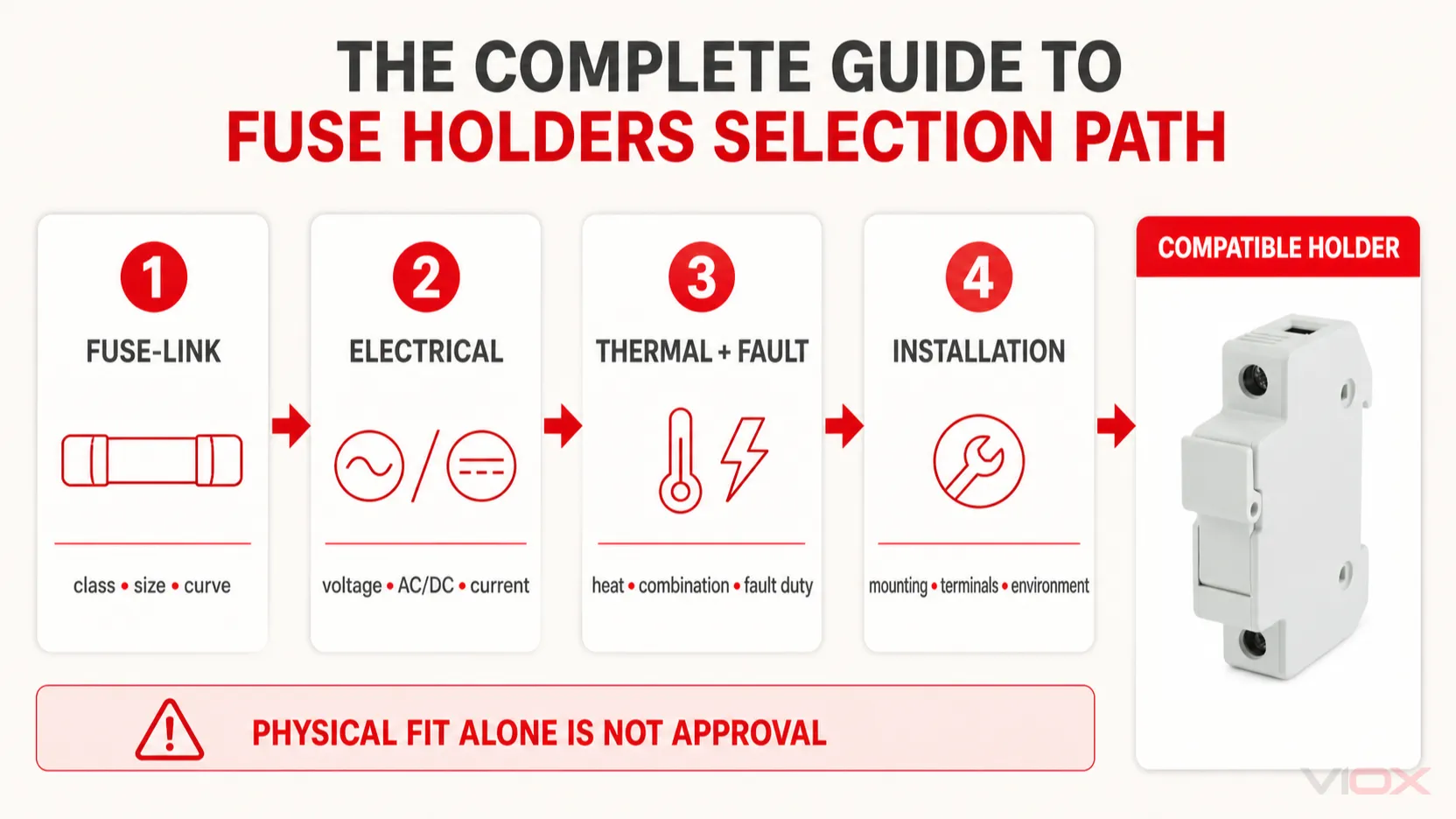
Step 1: Select the Fuse-Link and Fuse System First
Start with the protection study. Determine the required fuse utilization category or class, time-current behavior, rated voltage, rated current, breaking capacity and any required current-limiting or I²t performance. Then identify the exact fuse size and contact format.
The holder cannot correct an incorrectly selected fuse-link. Conversely, a correct fuse-link can still overheat or become unsafe in an incompatible holder.
Record at least:
- fuse standard and category or class;
- manufacturer series or standardized fuse system;
- body dimensions and terminal/contact format;
- fuse-link rated current and voltage;
- power dissipation data where provided;
- required accessories, striker or indication interface.
Step 2: Verify Physical Compatibility
The fuse must seat fully, contact the intended surfaces and be retained with the designed contact pressure. Similar body dimensions do not guarantee compatibility.
Check the datasheet for:
- accepted fuse-link designation and size;
- cylindrical diameter and length, or blade/tag geometry;
- rejection features that prevent the wrong fuse class or rating;
- carrier, cap and adapter part numbers;
- approved combinations rather than visual similarity.
Adapters and reducers should be used only when they are part of a documented system. Improvised metal spacers or modified contacts can increase resistance, weaken retention and defeat rejection features.
Step 3: Match Voltage and AC/DC Duty
The holder’s rated voltage must be at least the circuit voltage and must apply to the actual current type. Also check the manufacturer’s conditions of acceptability, insulation coordination and installation spacing.
Do not apply a vague safety margin or assume that a high AC marking automatically covers the same DC voltage. DC current does not have a natural current zero every half-cycle, and the complete fuse system must be documented for the intended DC duty.
The holder voltage marking alone also does not prove that the final panel has adequate creepage, clearance or enclosure spacing.
Step 4: Coordinate Circuit Current, Fuse Current and Holder Heating
Three different currents must not be confused:
- the normal circuit current;
- the fuse-link rated current chosen from the load and time-current study;
- the fuse-holder maximum current rating under stated conditions.
The fuse-link may be intentionally rated above normal circuit current to tolerate inrush. That does not permit the circuit current or thermal loading to exceed the holder’s limits.
Holder heating depends on contact resistance, terminal resistance, fuse-link power dissipation, conductor size, enclosure temperature, airflow, grouping and installation orientation. A rating established with a standardized test link may not reproduce the heat generated by the selected production fuse-link.
Use the manufacturer’s temperature-rise, power-dissipation and derating information for the exact combination. There is no responsible universal percentage that applies to every holder.
Step 5: Check Fault-Current and Complete-System Documentation
The prospective short-circuit current at the installation point must be within the capability of the specified protection system. The fuse-link’s breaking capacity is not a free-standing rating for every holder that it can physically enter.
Depending on the market and product category, documentation may state a short-circuit current rating, conditions of acceptability, tested fuse combinations or restrictions on enclosure and conductor arrangement. Evaluate the exact fuse-link/holder combination and the final equipment standard.
Do not describe the holder as “current limiting” unless the documentation assigns that behavior to the complete combination. Current limitation is primarily established by the fuse-link’s performance under the relevant test conditions.
Step 6: Match Mounting, Poles and Terminals
Choose the physical type from the equipment architecture:
- DIN rail for modular panel construction;
- panel mount for external service access;
- in-line for harness or localized protection;
- PCB for board-level protection;
- industrial base/block for larger fuse systems.
Then verify pole count, rail or panel dimensions, conductor entry direction, conductor material, terminal range, stripping length, ferrule or lug requirements and manufacturer tightening instructions.
The terminal must accept the actual conductor without trimming strands, doubling conductors without approval or placing insulation inside the contact zone.
Step 7: Define Access, Indication and Switching Requirements
Ask who will replace the fuse, whether energized parts can be reached, and whether the device will ever be operated while current is flowing.
Relevant features include:
- finger-safe or dead-front construction;
- carrier retention and tool requirements;
- fuse-status indication;
- auxiliary contacts or remote signaling;
- lockable operating mechanism;
- load-break or isolation rating, when genuinely required.
An indicator may use a small sensing current across an open fuse. Confirm its voltage range and whether leakage is acceptable for the connected load or control input.
Step 8: Verify the Environment
Define the real environment rather than selecting an indoor holder by catalog appearance. Consider:
- ambient temperature inside the operating enclosure;
- airflow and grouping with adjacent heat sources;
- dust, condensation, washdown or immersion;
- UV exposure and outdoor aging;
- salt, chemicals and corrosive gases;
- vibration, shock and cable movement;
- altitude where it affects insulation or cooling.
Use a documented ingress-protection rating only for the complete installed condition to which that rating applies. If the holder relies on the panel or outer enclosure for protection, include that boundary in the specification.
How to Read Fuse Holder Ratings
| Datasheet field | What it tells you | What it does not prove |
|---|---|---|
| Accepted fuse type/size | Physical and system compatibility | Correct fuse selection for the load |
| Rated voltage | Maximum application voltage under stated conditions | Suitability for both AC and DC unless both are stated |
| Rated current | Holder current limit under defined test conditions | Acceptable temperature rise in every enclosure |
| Power acceptance/dissipation | Thermal compatibility with the fuse-link | Complete panel cooling performance |
| Short-circuit rating or conditions | Fault-duty boundary for documented combinations | Universal use with any fuse that fits |
| Terminal range | Permitted conductor sizes and forms | Permission to use multiple conductors or unlisted lugs |
| IP rating | Tested ingress protection in a defined configuration | Protection if seals, caps or mounting conditions change |
| Pole count | Number of current paths in the assembly | Which conductors must be fused or switched in a given system |
| Indicator rating | Operating range of a status indicator | Zero leakage or compatibility with every PLC input |
| Standard/certification reference | Evaluation framework for that product | Compliance of the complete panel or machine |
Treat catalog data as a set of conditions, not a list of independent numbers. If the datasheet does not identify the fuse combination, test basis or installation conditions needed for your application, request the manufacturer’s technical file before specification.
Application Decisions
Industrial Control Panel
A DIN-rail modular holder is usually the practical starting point for branch control circuits because it integrates with terminal blocks and modular equipment. Selection still requires the exact cartridge size, circuit voltage, fault-current documentation, terminal range, panel temperature and touch-safety requirement.
If operators need to isolate a branch by opening the fuse device, specify a fuse switch-disconnector with the required operational rating rather than treating a pull-out holder as a switch.
PV Combiner Box
PV strings require a fuse-link and holder explicitly suitable for the maximum DC system voltage and environmental conditions. Confirm polarity-independent or polarity-specific behavior where applicable, conductor temperature, enclosure heating, outdoor protection and service procedure.
Protection and disconnect sizing depend on the array architecture and applicable installation rules. See How to Size Fuses and Disconnects in PV Combiner Boxes for that calculation task.
Power Supply or Electronic Equipment
PCB clips or panel-mount miniature holders are common. The main risks are insufficient spacing, board heating, incorrect cartridge size and unsafe user access. IEC 60127-6:2023 specifically covers holders for miniature fuse-links within its stated scope; it should not be used as a generic standard for industrial fuse systems covered elsewhere.
Wiring Harness or Mobile Equipment
An in-line holder can place protection close to the source without a panel. Match the blade or cartridge format, conductor cross-section, crimp tooling, sealing, strain relief, temperature and vibration duty. A holder hanging from unsupported wires is a mechanical failure waiting to develop.
Industrial Feeder or High-Current Distribution
Use the standardized fuse system and its documented base or block. Evaluate busbar or cable terminations, barriers, phase spacing, authorized-person access and the method for safe fuse replacement. The holder should be treated as part of the power-distribution assembly, not as an isolated accessory.
Common Fuse Holder Selection Mistakes
Selecting by Ampere Marking Alone
The same current marking can appear on products with different fuse formats, voltage duties, terminals, thermal conditions and standards. Current is only one input.
Assuming That a Fuse Which Fits Is Compatible
Physical insertion does not prove contact pressure, rejection-system compliance, power-dissipation compatibility or fault-duty suitability.
Using the Fuse Holder as a Routine Switch
A removable carrier is not evidence of load-break capability. De-energize according to the equipment instructions unless the product is explicitly rated for the intended switching duty.
Ignoring Enclosure Temperature
The air inside a compact panel can be much hotter than the room. Adjacent power devices, grouped holders and limited airflow can raise terminal and contact temperatures even when the circuit current appears acceptable.
Treating AC and DC Ratings as Interchangeable
Use the exact AC or DC marking and the approved fuse combination. Do not transfer an AC rating to a DC system by assumption.
Reusing Heat-Damaged Components
Discoloration, softened plastic, weak fuse retention, pitted contacts or burnt insulation indicate that the current path has been compromised. Replacing only the fuse-link does not repair the holder or terminal.
Inspection and Replacement Triggers
Inspection must be performed under an electrically safe work condition and according to the equipment manufacturer’s procedure. Look for:
- discoloration, odor, deformation or melted material;
- loose, corroded or contaminated contacts;
- weak carrier retention or mechanical damage;
- damaged seals, caps or touch guards;
- conductor insulation pulled into the terminal or exposed strands;
- abnormal temperature difference compared with equivalent loaded poles;
- repeated fuse operation without a confirmed circuit fault.
Do not clean, bend or retension contacts unless the manufacturer permits that service action. Replace the holder when heat or mechanical damage has altered the contact system or insulation. After replacement, investigate the load, fuse selection, conductor preparation, terminal torque and enclosure temperature so the failure is not repeated.
Fuse Holder RFQ Checklist
Send the following information when requesting a fuse holder quotation or technical review:
- Applicable IEC, UL or equipment standard.
- Exact fuse-link manufacturer, series, size, class/category and rated current.
- System voltage, AC/DC, frequency where relevant and grounding arrangement.
- Normal circuit current, load type and inrush profile.
- Prospective short-circuit current at the installation point.
- Mounting type, pole count and available panel or PCB space.
- Conductor material, cross-section, quantity and termination type.
- Maximum enclosure ambient temperature, grouping and airflow.
- Required IP, UV, corrosion, vibration or altitude conditions.
- Touch-safety, indication, auxiliary-contact, switching or isolation requirements.
- Required certification documents, test reports and approved fuse combinations.
VIOX supplies low-voltage fuses and fuse-holder solutions for industrial and electrical-distribution applications. Review the VIOX fuse product range or send the completed checklist to [email protected] for a model-level review. Final selection must be verified against the relevant datasheet and equipment standard.
Frequently Asked Questions
What are the main types of fuse holders?
The main mounting types are DIN-rail modular, panel-mount, in-line, PCB/open-clip and industrial fuse base or block designs. Within each group, the accepted fuse system, voltage, AC/DC duty, current, terminals and environmental protection still have to be verified.
Should the fuse or the fuse holder be selected first?
Select the fuse-link from the protection requirements first, then select a holder approved for that exact fuse system and suitable for the circuit and installation. In some designs the available holder can constrain the fuse choice, so both must be checked before the design is frozen.
Can a fuse holder have a lower current rating than the fuse?
The normal circuit current must not exceed the holder’s permitted current under the stated conditions. A fuse-link can sometimes have a higher ampere rating than the normal load to tolerate inrush, but the combination requires a thermal check using the exact fuse power dissipation and holder guidance. Physical compatibility alone is insufficient.
Can an AC fuse holder be used for DC?
Only when the manufacturer explicitly rates the holder and the selected fuse combination for the required DC voltage and application. Do not infer a DC rating from an AC marking.
Is a fuse holder a disconnect switch?
Not automatically. Use it as a switching or isolation device only when the product has the required load-break or disconnecting rating and the installation follows its instructions. Otherwise, de-energize the circuit before removing the carrier or fuse-link.
What causes a fuse holder to overheat?
Common causes include loose or contaminated contacts, incorrect conductor preparation, insufficient terminal torque, a damaged carrier, excessive circuit current, high fuse-link power dissipation, grouping and high enclosure temperature. The fault must be corrected before the holder is returned to service.