On this page
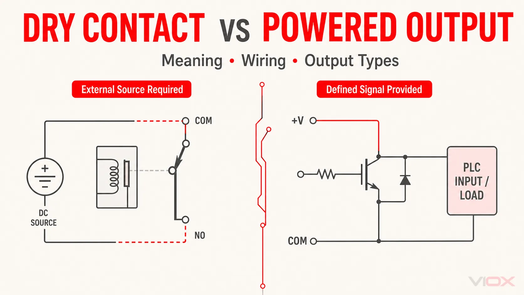
A dry contact is an unpowered switching path. It opens or closes a circuit, but the device does not supply the voltage on the contact terminals; the monitored or controlled circuit needs an external source. A wet contact, as the term is commonly used in control wiring, is a powered output that presents a switched voltage or current referenced to the device supply or common.
Do not identify either type from wire count alone. Identify the output element in the datasheet—relay, transistor, triac, or solid-state switch—then trace the voltage source, output common, load, and return path. “Voltage-free” also does not mean that a dry contact can switch any voltage. Its AC/DC voltage, current, load type, minimum load, and insulation ratings still apply.
Terminology boundary: “Wet contact” is informal and can be ambiguous. Some documents use wet contact for a powered output; others discuss mercury-wetted relays or contact wetting current. In specifications and RFQs, write powered output, sourcing transistor output, sinking transistor output, or relay dry contact whenever possible.
Dry Contact vs Wet Contact at a Glance
| Comparison point | Dry contact | Powered or “wet” output |
|---|---|---|
| What the terminal does | Opens or closes a conductive path | Switches an internally or externally fed electronic output referenced to a supply/common |
| Does the output supply a voltage by itself? | No | Normally presents a specified powered signal when active |
| Typical implementation | Electromechanical relay contact, reed contact, microswitch, or isolated contact output | PNP/NPN transistor, open-collector/open-drain stage, triac, or another powered semiconductor output |
| External circuit source | Required | Device and output architecture determine the source; a field supply may still be required at a module common |
| Polarity | Mechanical contact is normally non-polar, subject to its ratings | Often polarity- and common-dependent |
| Off-state leakage | Ideally negligible for a mechanical open contact; verify accessories and module circuitry | Semiconductor outputs normally specify leakage current |
| Isolation | Possible, but only the datasheet proves the isolation boundary and rating | May be isolated or non-isolated; powered does not automatically mean non-isolated |
| Voltage flexibility | The switched circuit chooses the voltage, within the contact ratings | Restricted to the output’s stated voltage range and topology |
| Key datasheet fields | Contact form, AC/DC switching ratings, load type, minimum applicable load, common grouping, dielectric data | Output type, source/sink logic, voltage range, current, leakage, voltage drop, common grouping, short-circuit protection |
The practical decision is not which type is universally better. Use the interface that matches the receiving input or load, then verify every rating that controls the complete circuit.
The Circuit Boundary Is the Real Difference
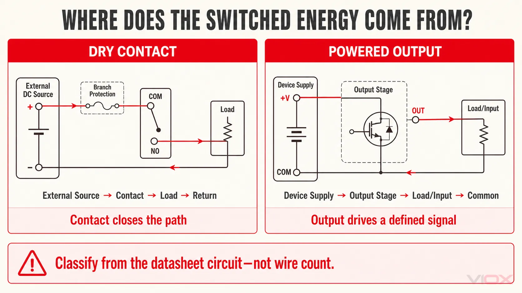
The word contact can hide where the switched energy comes from. Draw the boundary around the output device and ask one question: does the output terminal merely close a path, or does it drive the path to a defined electrical potential?
Dry contact: the external circuit supplies the energy
A relay output with common (COM), normally open (NO), and normally closed (NC) terminals is a typical dry-contact interface. The control electronics energize the relay coil, but the contact side is a separate switching path. Schneider Electric, for example, describes relay terminals in its System 450 controls as dry contacts that do not supply power to the controlled system and directs users to the electrical ratings before wiring.
The basic current path is:
external source → fuse/protection → COM → closed NO contact → load/input → returnBefore the external source is connected, the contact pair has no internally generated output voltage. After installation, however, the terminals may carry the external circuit voltage. A dry contact is therefore not necessarily safe to touch, extra-low voltage, or de-energized.
Powered output: the output establishes a signal potential
A PNP sensor output is a common powered-output example. The sensor receives DC power and, when active, switches its output toward the positive supply. An NPN sensor instead switches its output toward the return or 0 V side. PLC transistor outputs follow similar sourcing or sinking logic, although module commons and protection arrangements vary.
The signal still needs a complete loop. “Powered output” does not mean that field wiring needs no supply or return. It means the output is electrically tied to a defined source/common architecture rather than behaving as an independent mechanical contact.
How to Identify a Dry Contact or Powered Output Reliably
Use the circuit diagram and output specifications. Terminal count can suggest what to inspect, but it cannot prove the output type: two-wire electronic sensors exist, four-wire sensors may have complementary transistor outputs, and PLC modules are available with relay, transistor, and triac outputs.
1. Find the output technology
Look for one of these explicit descriptions:
- relay output, volt-free contact, potential-free contact, or dry contact;
- PNP/sourcing transistor output;
- NPN/sinking transistor output;
- open collector or open drain;
- triac output;
- solid-state relay (SSR) or MOSFET relay output.
Siemens’ S7-200 SMART system documentation is a useful example of why the technology matters: its output specifications distinguish solid-state MOSFET outputs from relay dry-contact outputs and give them different voltage ranges, current limits, leakage behavior, and on-state characteristics.
2. Read the internal schematic, not just the label
| Datasheet clue | Likely interpretation | What still needs verification |
|---|---|---|
| COM, NO, and NC beside a relay-contact symbol | Changeover or single-pole relay contact | Contact voltage/current, common isolation, load type, minimum load |
| Two contact terminals shown electrically separate from the coil or electronics | Potential-free switching path | Dielectric rating and whether other channels share a common |
| PNP, sourcing, or arrow toward the output from +V | Positive-side transistor output | Compatible sinking input, voltage range, current, leakage |
| NPN, sinking, or output transistor to 0 V | Negative-side transistor output | Compatible sourcing input, voltage range, current, leakage |
| Q, OUT, or DO with a module COM/+V terminal | Could be relay or semiconductor | Internal circuit drawing is required; “COM” alone proves nothing |
| Off-state leakage or on-state voltage-drop specification | Usually a semiconductor output | Whether the receiving load can tolerate those values |
| Minimum applicable load or contact failure-rate reference | Mechanical relay or switch contact | Suitability for the actual signal current and environment |
3. Trace source, switch, load, and return
Mark four points on the drawing:
- Where does the circuit voltage originate?
- Which element opens or closes the current path?
- What receives the current?
- How does current return to the source?
If any point is missing, the circuit is not ready for wiring. This simple path check catches the two most common interface errors: expecting a dry contact to generate voltage and connecting a powered output to an incompatible common.
4. Use measurements only within a safe test plan
With the circuit isolated and verified de-energized, a mechanical dry contact can usually be checked for open/closed continuity between its specified terminals. Never use resistance or continuity mode on an energized circuit.
Voltage testing of an energized control circuit should be performed only by a qualified person using the correct instrument, category rating, personal protective equipment, and procedure. A voltage observed at a dry-contact terminal normally comes from the external circuit; it does not reclassify the output as a powered output.
Dry Contact Wiring Diagrams: Three Common Interfaces
Terminal names and input common arrangements differ by manufacturer. Treat the following as circuit-path models, then match them to the actual device schematic.
1. Dry contact to a 24 VDC PLC digital input
+24 VDC ── branch protection ── dry NO contact ── PLC digital input
  0 VDC ───────────────────────────────────────── PLC input COM
When the contact closes, the external 24 VDC source drives current through the PLC input circuit and back through its common. If the input LED does not turn on even though the contact closes, verify the input common, return path, input voltage range, and channel configuration.
Some input modules provide their own sensing or wetting source for a contact input; others expect the panel designer to supply it. The module wiring diagram decides which arrangement applies.
2. PLC or controller relay output driving an external load
source +/line ── branch protection ── relay COM
relay NO ── load or interposing-relay coil ── source return/neutral
The PLC logic energizes the internal relay, but the field circuit supplies the load energy. Select the contact using the actual AC or DC load type—not merely the steady-state current. Solenoids, contactor coils, lamps, and capacitive inputs can impose inrush or turn-off stress. Use the load manufacturer’s recommended suppression and verify that the suppression method is compatible with AC/DC polarity and required release time.
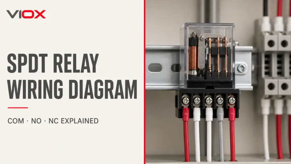
For a detailed contact arrangement, see the VIOX SPDT relay wiring diagram. For a PLC output that cannot safely drive the final load, use the decision process in direct drive vs interposing relays.
3. PNP powered sensor to a compatible PLC input
+24 VDC ───────── sensor +V
  0 VDC ───────── sensor 0 V
sensor PNP OUT ── PLC digital input
  0 VDC ───────── PLC input COM
When active, the PNP output sources positive voltage/current to a compatible sinking input. An NPN output normally switches the signal toward 0 V and requires a compatible sourcing input arrangement. Because manufacturer terminology and common wiring vary, confirm the input schematic rather than relying only on the PNP/NPN label.
The VIOX NPN vs PNP proximity sensor guide covers that separate sourcing/sinking decision in more depth.
PLC Output Types: Not Every Output Is a Dry Contact
The phrase “PLC digital output” describes its logic function, not its hardware. The hardware determines whether the output behaves as a dry contact or a powered electronic switch.
| PLC or controller output | Dry contact? | Typical circuit behavior | Engineering checks |
|---|---|---|---|
| Electromechanical relay output | Usually, when the contact set is specified as potential-free | COM switches to NO or NC; external circuit supplies load power | AC/DC contact ratings, resistive vs inductive load, common grouping, mechanical/electrical life, minimum load |
| DC transistor output | No | Sources or sinks DC through a semiconductor | Polarity, compatible input/load, voltage range, current, leakage, on-state voltage, protection |
| AC triac output | No | Switches AC electronically and may require minimum load/holding current | AC-only boundary, off-state leakage, load current, zero-cross behavior where specified |
| SSR or MOSFET output | Do not assume | May be isolated and may emulate a contact, but remains a semiconductor path | Permitted AC/DC direction, on-resistance or voltage drop, leakage, thermal limits, short-circuit behavior |
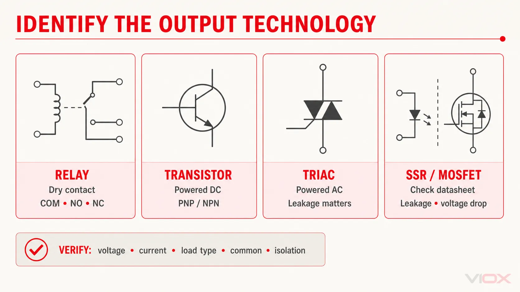
An isolated semiconductor output can separate logic from the field circuit without becoming a mechanical dry contact. Conversely, a relay symbol does not prove that every channel is isolated from every other channel; several outputs may share a common. Check the channel-to-channel and field-to-logic insulation specifications.
For the broader technology tradeoff, see electromechanical relay vs solid-state relay.
When to Choose Each Interface
| Operating condition | Prefer dry contact | Prefer powered output | Consider powered output plus interposing relay |
|---|---|---|---|
| Receiving circuit chooses its own voltage | Yes, within contact ratings | Only if the voltage/common match | Useful when the controller output voltage differs from the load circuit |
| Need to switch both AC and DC across different applications | Possible only when both ratings are specified | Normally tied to one technology and voltage range | Often the safer modular architecture |
| High switching frequency or long cycle requirement | Mechanical wear may be limiting | Transistor/SSR often fits better | Use when fast control must interface with a separate load circuit |
| Very small sensing current | Check minimum applicable load and contact material | Check leakage and receiving-input threshold | A signal relay or suitable interface module may improve reliability |
| Load has high inrush or inductive turn-off energy | Contact utilization and suppression are critical | Semiconductor surge and clamp limits are critical | Lets the PLC switch a coil while rated contacts switch the field circuit |
| Receiving input cannot tolerate off-state leakage | Mechanical dry contact may be advantageous | Leakage must be checked | Interposing relay can provide a clearer open circuit where justified |
| Polarity-independent switching is needed | Mechanical contacts may fit | Many semiconductor outputs are polar | Use a properly rated relay interface |
A common industrial architecture uses both types: a PLC transistor output energizes an interposing relay coil, and the relay’s dry contacts switch or signal a separate circuit. This adds a component, but it can solve voltage mismatch, common-reference, serviceability, and load-duty problems when the ratings support the design.
“Dry” Does Not Override the Electrical Ratings
Before connecting any dry contact, verify all of the following:
- Maximum switching voltage: check AC and DC separately. A DC arc does not benefit from a natural current zero crossing, so a contact may have a much lower DC switching capability than its AC rating.
- Switching current and power: steady-state current alone may not represent inrush, lamp, capacitive, motor, or solenoid duty.
- Load type or utilization category: a resistive rating cannot automatically be applied to an inductive coil.
- Minimum applicable load: a power relay that works reliably at higher current may not be suitable for a very small PLC input or instrumentation signal.
- Contact form and normal state: verify COM/NO/NC and the defined de-energized condition.
- Common grouping and insulation: determine which channels share a common and what separation is actually rated.
- Protection and suppression: coordinate branch protection and use suitable flyback, diode-plus-zener, RC, varistor, or manufacturer-specified suppression for the load and release-time requirement.
- Failure behavior: decide what the receiving system should see after loss of control power, broken wiring, welded contact, or failed semiconductor.
Omron’s relay guidance emphasizes that contact ratings depend on applied voltage and load type, and that minimum-load reliability depends on contact material, arrangement, environment, and actual operating conditions. For inductive switching, the VIOX guide to time relay contacts on inductive loads explains why a simple ampere comparison is insufficient.
Wet Contact Is Not the Same as Wetting Voltage
The query wetting voltage refers to contact reliability, not to whether an output is powered.
Mechanical contact surfaces can develop oxide or contamination films. At very small loads, the switched electrical energy may be insufficient to disrupt the film, so contact resistance becomes unstable. Relay manufacturers commonly express the boundary as a minimum applicable load, a reference failure level, or a load-dependent operating area rather than one universal wetting voltage.
Keep these terms separate:
- dry contact / potential-free output: an interface that does not supply its own switched potential;
- powered or wet output: an output that drives a defined electrical signal;
- wetting current or wetting voltage: the current or voltage condition needed to maintain reliable conduction through a mechanical contact surface;
- dry circuit: in some relay literature, a circuit operating at very low energy, possibly below the effective contact-cleaning level.
A dry-contact output can therefore switch a circuit above its specified minimum applicable load. The words dry contact and dry circuit do not describe the same design decision.
Fault-Isolation Table
| Symptom | Likely boundary error | Verification | Corrective direction |
|---|---|---|---|
| Relay output changes state, but the PLC input remains off | External sensing supply, input common, or return path is missing | With power isolated, verify contact continuity; under an authorized live test, trace source-to-input voltage against the module diagram | Complete the external loop and connect the correct input common |
| Output terminal has no voltage when the relay turns on | The relay output is a dry contact, not a source | Check whether the datasheet calls it relay/dry/volt-free and locate COM/NO/NC | Add the correctly rated external source and branch protection |
| Sensor LED changes, but PLC input does not | PNP/NPN source-sink mismatch or wrong common | Compare the sensor output circuit with the PLC input circuit | Match sourcing output to sinking input, or sinking output to sourcing input |
| Load remains faintly energized when output is off | Semiconductor leakage current exceeds the load’s off threshold | Compare off-state leakage with the load or input reset current | Use a compatible load/interface or an approved bleed/interposing solution |
| Relay works with a larger test load but is unreliable on a small signal | Minimum applicable load or contact-film issue | Check the relay’s minimum-load and contact-material data; do not infer reliability from continuity alone | Select a signal relay/contact suited to the actual load or use a compatible interface |
| Contact fails after switching a coil or valve | Inductive turn-off stress or inrush exceeds the contact duty | Review load current waveform, AC/DC rating, utilization/load category, and suppression | Apply suitable suppression or an appropriately rated interposing device |
| Several channels behave unexpectedly after one common is rewired | Output channels share a common or supply group | Inspect the module’s internal common-group diagram | Rewire by group and preserve the specified isolation boundaries |
Pre-Energization Interface Checklist
Before applying power, confirm:
- The datasheet identifies the output as relay, transistor, triac, SSR, or another defined technology.
- The complete source–switch–load–return path is visible on the drawing.
- PLC input and sensor output use compatible sourcing/sinking logic.
- External supply voltage and polarity match every device in the loop.
- Contact or output ratings cover AC/DC type, steady current, inrush, inductive duty, and switching frequency.
- Minimum applicable load and off-state leakage are compatible with the receiving device.
- Common groups and insulation boundaries are understood rather than assumed.
- Branch protection and load suppression follow the device and load documentation.
- Continuity tests are performed only on isolated, verified de-energized circuits.
- The final circuit is verified against the exact manufacturer wiring diagram and applicable project requirements.
Frequently Asked Questions
What is a dry contact?
A dry contact is an unpowered switching interface. It opens or closes a conductive path but does not generate the voltage used by the switched circuit. An external source, load or input, and return path are required to make a complete operating circuit.
Is a dry contact always at zero volts?
No. It has no internally supplied contact voltage before the field circuit is connected. Once wired, the contact terminals can carry the external circuit voltage, including a hazardous voltage if the ratings and design permit it. Isolate the circuit before continuity testing.
Can a dry contact switch both AC and DC?
Only when the datasheet provides suitable ratings for both. AC and DC switching capabilities can differ substantially, especially with inductive loads. Verify voltage, current, load type, inrush, and suppression rather than relying on the dry-contact label.
Is every PLC output a dry contact?
No. A PLC may use relay dry contacts, DC sourcing or sinking transistors, AC triacs, or other solid-state outputs. The module code, internal schematic, terminal arrangement, and electrical specifications determine the output type.
What is the difference between a wet contact and a powered output?
In control-wiring discussions, the terms are often used for the same general idea: the output presents a switched electrical potential referenced to the device supply or common. Because wet contact has other meanings, powered output, PNP output, NPN output, or triac output is more precise.
Is wetting voltage the same as wet-contact voltage?
No. Wetting voltage or wetting current concerns the minimum electrical condition needed for reliable mechanical-contact conduction through surface films. It is separate from whether an interface is a dry contact or a powered output. Use the relay manufacturer’s minimum applicable load data rather than assuming a universal value.
How do you test a dry contact?
First isolate the circuit and verify that it is de-energized. Then use continuity or resistance mode across the specified COM–NO or COM–NC terminals while commanding the output through its states. Energized voltage tests require a qualified person, an appropriate instrument, and the device’s wiring procedure.