On this page
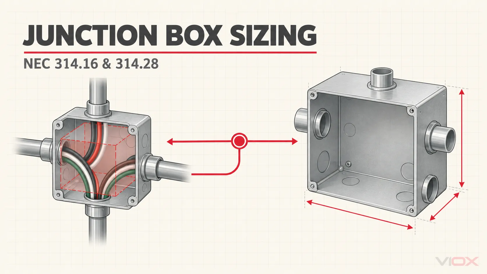
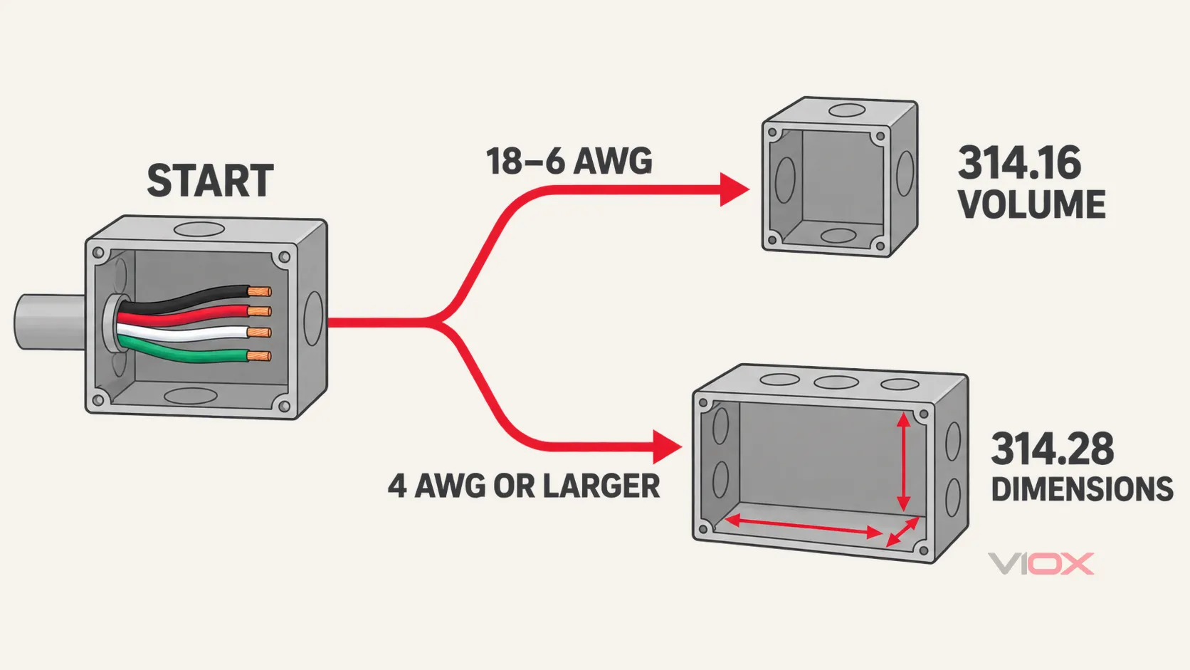
Use two different sizing paths. For boxes containing common 18 through 6 AWG conductors, NEC 314.16 determines the minimum volume from conductors, grounding conductors, clamps, fittings, and device yokes. For pull or junction boxes containing 4 AWG or larger insulated conductors in a raceway or cable run, NEC 314.28 determines minimum dimensions from raceway size and pull geometry. There is no single standard junction-box size that fits every installation.
| What is inside the box? | Primary sizing path | Result you calculate |
|---|---|---|
| Conductors covered by the 18–6 AWG volume allowances | NEC 314.16 box fill | Minimum internal volume, usually in cubic inches |
| 4 AWG or larger insulated conductors in raceway or cable runs | NEC 314.28 pull/junction-box sizing | Minimum box dimension for each pull direction |
| A mix of conditions or equipment terminals | Apply every relevant rule | Use the most restrictive resulting requirement |
This guide uses the 2023 NEC treatment for its box-fill examples because grounding-conductor allowances differ across code cycles. Before using any result for design, permitting, or inspection, verify the NEC edition adopted by the authority having jurisdiction (AHJ), local amendments, the box marking, and the product listing. NFPA maintains access to multiple editions of NFPA 70, the National Electrical Code, so the latest published edition is not automatically the edition enforced at a project location.
NEC 314.16 Box-Fill Calculation
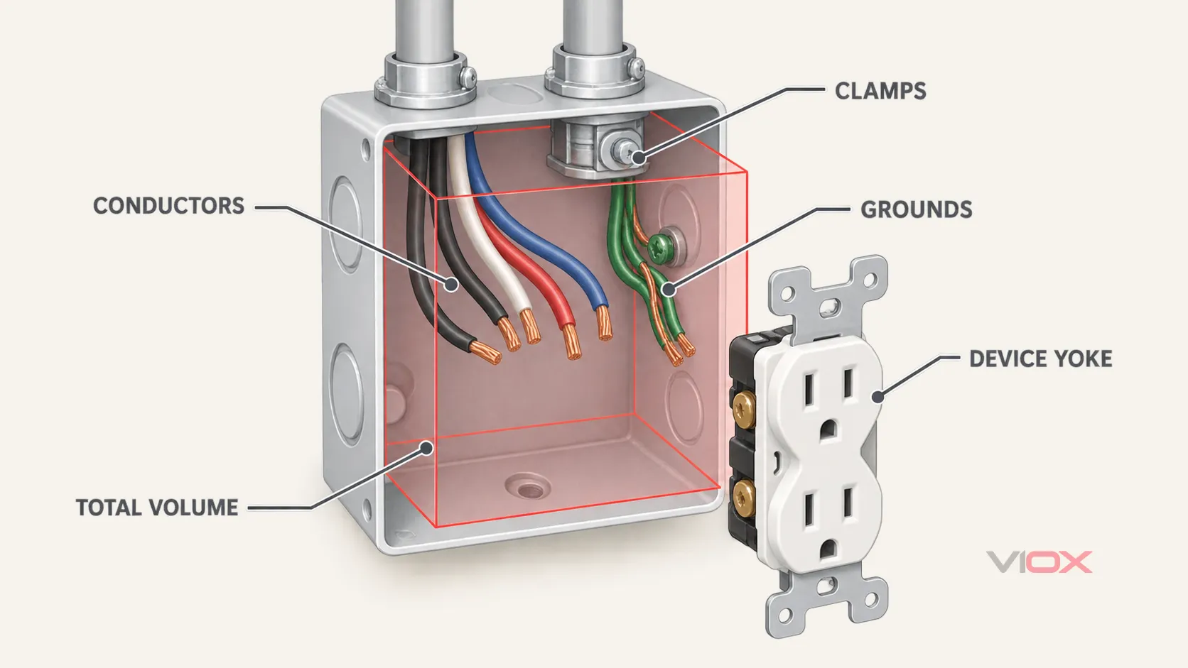
NEC 314.16 is a volume calculation. The required box volume is the sum of the allowances for the insulated conductors, equipment grounding conductors, internal clamps, support fittings, and device yokes in the box.
The working formula is:
Required box volume = conductor fill + clamp fill + support-fitting fill + device/equipment fill + equipment-grounding-conductor fill
Do not reduce the calculation to “number of wires × one value” unless every counted item has the same allowance and the box contains no devices or internal fittings.
Step 1: Record Every Insulated Conductor
For each conductor size, identify how many conductors must be counted:
- A conductor that originates outside the box and is spliced or terminated inside normally counts once.
- An unbroken conductor that passes through the box normally counts once.
- A conductor entirely contained within the box generally does not receive a conductor-fill allowance under the basic conductor rule.
- Long loops or coils can require additional allowances; check the exact language in the adopted NEC edition rather than treating every internal loop as a pigtail.
Mixed conductor sizes retain their individual volume allowances. Four 14 AWG conductors and two 12 AWG conductors are not calculated as six identical conductors.
Step 2: Add Internal Clamp and Support-Fitting Fill
One or more internal cable clamps together generally add one volume allowance based on the largest conductor present in the box. A connector whose clamping mechanism is outside the box does not use the same internal-clamp allowance.
Internal support fittings such as fixture studs or hickeys also require an allowance under the applicable rule. Identify what is actually inside the box; do not add an allowance merely because a cable connector is visible from outside.
Step 3: Add Device-Yoke Fill
Each yoke or strap containing a switch, receptacle, or other device normally requires a double volume allowance based on the largest conductor connected to that yoke. A wider device occupying more than one gang can require additional allowances under the adopted edition.
This is why an empty splice box and a device box with the same insulated conductor count may need different volumes.
Step 4: Count Equipment Grounding Conductors by NEC Edition
Grounding-conductor fill is edition-sensitive. Under the 2023 NEC approach used in the examples below:
- up to four equipment grounding conductors entering the box use one volume allowance based on the largest entering equipment grounding conductor;
- each additional entering equipment grounding conductor or applicable bonding jumper adds one-quarter of that largest-conductor allowance.
The older shortcut “all grounds together count as one” can understate the required volume when more than four grounding conductors enter the box. NFPA’s public development material for 314.16(B)(5) equipment grounding conductor fill documents the 2023-edition approach. Use the wording in the edition adopted for the project; do not apply this example across every NEC cycle.
Step 5: Convert Each Allowance to Volume
The following values are the common conductor-volume allowances shown in NEC Table 314.16(B). NFPA’s public NEC development material also shows the 314.16(B) allowance table and component rules.
| Conductor size | Volume per allowance | Metric volume |
|---|---|---|
| 18 AWG | 1.50 in³ | 24.6 cm³ |
| 16 AWG | 1.75 in³ | 28.7 cm³ |
| 14 AWG | 2.00 in³ | 32.8 cm³ |
| 12 AWG | 2.25 in³ | 36.9 cm³ |
| 10 AWG | 2.50 in³ | 41.0 cm³ |
| 8 AWG | 3.00 in³ | 49.2 cm³ |
| 6 AWG | 5.00 in³ | 81.9 cm³ |
For mixed sizes, calculate each group separately. Clamps and support fittings use the largest conductor present under their applicable rule; a device yoke uses the largest conductor connected to that device.
Worked Box-Fill Example: Two 12/2 Cables and One Receptacle
Assume a device box contains:
- two 12/2 cables, producing four insulated 12 AWG conductors;
- one receptacle on a single yoke, connected with 12 AWG conductors;
- internal cable clamps;
- two 12 AWG equipment grounding conductors entering the box;
- no additional support fitting.
Using the 2023 NEC approach:
| Component | Allowance count | Allowance basis | Required volume |
|---|---|---|---|
| Four insulated conductors | 4 | 2.25 in³ | 9.00 in³ |
| Internal clamps | 1 | 2.25 in³ | 2.25 in³ |
| Receptacle yoke | 2 | 2.25 in³ | 4.50 in³ |
| Two equipment grounding conductors | 1 | 2.25 in³ | 2.25 in³ |
| Total | 8 | 18.00 in³ |
The minimum calculated volume is 18.00 cubic inches. The next step is not to assume that every single-gang box provides 18 in³. Verify the volume marked on the actual box or use the applicable code table for the box’s exact dimensions and construction. If the selected box is marked 18.0 in³, it meets the numerical minimum in this example, but a larger listed box may make conductor folding, device installation, and future service easier.
Mixed-Size Calculation Rule
Suppose the insulated-conductor portion instead contains four 14 AWG conductors and two 12 AWG conductors:
- 4 × 2.00 in³ = 8.00 in³
- 2 × 2.25 in³ = 4.50 in³
The insulated-conductor subtotal is 12.50 in³. Do not multiply all six conductors by 2.25 in³. Only the allowances for clamps, support fittings, device yokes, and grounding conductors use their specified largest-conductor basis.
Why There Is No Universal “Standard Junction Box Size”
Standardized box dimensions and listed volumes exist, but a description such as single-gang, 4-inch square, or 100 × 100 mm does not by itself prove that a box has enough usable volume for a particular installation.
Usable volume can change with:
- box depth and construction;
- integral clamps or internal projections;
- extension rings or covers with a declared volume;
- device yokes and fittings;
- conductor sizes and quantities;
- the applicable national code and product listing.
For NEC box fill, compare the calculated requirement with the volume marked by the manufacturer or the exact entry in the applicable NEC table. Millimeter dimensions from a product catalog describe physical size; they do not replace the code calculation.
NEC 314.28 Pull- and Junction-Box Sizing
NEC 314.28 changes the sizing problem from internal volume to physical pull dimensions. It applies to pull and junction boxes and conduit bodies used with 4 AWG or larger insulated conductors under its stated scope. The result depends on whether the conductors make a straight pull, angle pull, U-pull, or splice arrangement.
The NFPA material for 314.28 states the 8× straight-pull rule and the dimensional approach for larger conductors. Calculate each applicable wall and pull direction; a single formula does not automatically establish length, height, and depth.
Straight Pull: 8× the Largest Raceway
A straight pull enters one wall and leaves the opposite wall without changing direction.
Minimum distance in the pull direction = 8 × trade size of the largest raceway
If the largest raceway in a straight pull is trade size 2:
8 × 2 in = 16 in
The box therefore needs at least 16 inches in that pull direction. This result does not determine the other box dimensions or override conductor-bending, terminal, listing, or installation requirements that may also apply.
Angle Pull, U-Pull, or Splice: 6× Plus the Other Raceways
For an angle pull, U-pull, or applicable splice arrangement, calculate from each wall and raceway row involved:
Minimum wall-to-opposite-wall distance = 6 × largest raceway in the row + sum of the trade sizes of the other raceways in that row on the same wall
Repeat the calculation for every relevant row and wall. The largest result controls that box dimension.
Where two raceway entries contain the same conductor run, their spacing must also satisfy the applicable minimum based on six times the trade size of the larger raceway. This entry-to-entry requirement is separate from the wall-to-opposite-wall calculation.
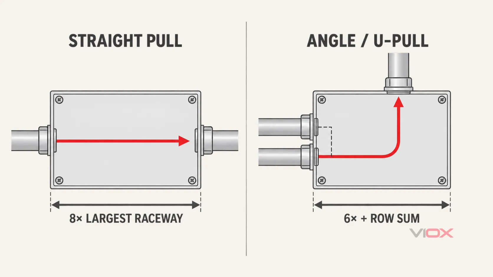
Worked Straight-Pull Example
Two trade-size 2 raceways enter opposite walls and carry 4 AWG or larger insulated conductors in a straight pull.
- Identify the largest raceway: 2 inches.
- Apply the straight-pull multiplier: 8 × 2 inches.
- Minimum box length in the pull direction: 16 inches.
Record the result as a controlled dimension, not as a complete box size:
| Direction checked | Pull type | Calculation | Minimum dimension |
|---|---|---|---|
| Left wall to right wall | Straight | 8 × 2 in | 16 in |
The height and depth still require verification from the full layout, conductors, fittings, and enclosure specification.
Worked Combination-Pull Example
Assume the following raceways are in the same plane:
- left wall: one trade-size 3 raceway and one trade-size 2 raceway in the same row;
- right wall: one trade-size 2 raceway;
- top wall: one trade-size 3 raceway;
- the 2-inch raceways form a straight pull from left to right;
- the 3-inch raceways form an angle pull from the left wall to the top wall.
Horizontal Dimension
Check both conditions affecting the left-to-right dimension.
Straight pull:
8 × 2 in = 16 in
Angle pull calculated from the left wall:
(6 × 3 in) + 2 in = 20 in
The larger result controls, so the minimum horizontal dimension is 20 inches.
Vertical Dimension
Calculate from the top wall, which has one trade-size 3 raceway in the applicable row:
6 × 3 in = 18 in
The minimum vertical dimension is 18 inches.
For the two 3-inch raceways carrying the same conductor run, also verify at least 18 inches between their entries using the applicable 6× spacing rule.
The calculated face dimensions for this simplified layout are therefore at least 20 × 18 inches. Depth and any additional requirements remain project-specific. If the raceways are not in the assumed row or plane, redraw the layout and recalculate each wall rather than reusing this answer.
Junction Box Sizing Worksheet
Use this worksheet before selecting an enclosure.
Path A: NEC 314.16 Volume
| Input | Project value |
|---|---|
| Adopted NEC edition and local amendments | |
| Insulated conductor quantity by AWG size | |
| Pass-through conductors or long loops | |
| Internal cable clamps | |
| Internal support fittings | |
| Device yokes and largest connected conductor | |
| Entering equipment grounding conductors by size | |
| Required volume subtotal for each item | |
| Total required volume | |
| Box marked/listed volume | |
| Pass: box volume ≥ required volume |
Path B: NEC 314.28 Dimensions
| Input | Project value |
|---|---|
| Adopted NEC edition and local amendments | |
| Largest conductor size | |
| Raceway trade size at every entry | |
| Pull type for every conductor run | |
| Straight-pull result for each axis | |
| Angle/U-pull result for each wall and row | |
| Same-conductor raceway-entry spacing | |
| Largest controlling length | |
| Largest controlling height | |
| Required depth and other equipment constraints | |
| Selected box meets every controlled dimension |
Final Verification Before Selection
- Confirm whether the enclosure is functioning as a junction box, pull box, tap box, device box, or more than one of these. The VIOX guide to junction boxes, pull boxes, and tap boxes explains that functional boundary.
- Verify the NEC edition adopted locally; do not mix grounding-conductor rules from different editions.
- Check the actual box marking, listing, dimensions, and manufacturer instructions.
- For 314.16, retain the component-by-component volume calculation.
- For 314.28, retain a wall-by-wall drawing showing raceway trade sizes and conductor paths.
- Apply accessibility, support, cover, entry, and bonding requirements separately. See the broader NEC junction-box requirements guide for those topics.
- Ask the AHJ or project electrical designer to resolve ambiguous layouts before ordering or installation.
After the calculation is complete, compare the required dimensions, material, entry configuration, and environmental rating with the available VIOX junction box manufacturing options. A product selection should document how the marked or declared enclosure data satisfies the calculated requirement; appearance or nominal face size is not enough.
Safety and code note: This article is an engineering reference, not a substitute for the adopted NEC, local amendments, product listings, project specifications, or AHJ interpretation. De-energize and verify electrical equipment before inspection or modification, and use qualified personnel for code-regulated work.