このページについて
SSRのデータシートには、規定の試験条件下における最大電圧および電流が記載されています。制御盤には、デバイスの信頼性を左右する一般的な条件が加わります。それには、モータ始動電流、コンデンサ充電パルス、筐体内にこもる熱、近接配置された電力機器、および公称負荷定格には現れない過渡現象などが含まれます。.
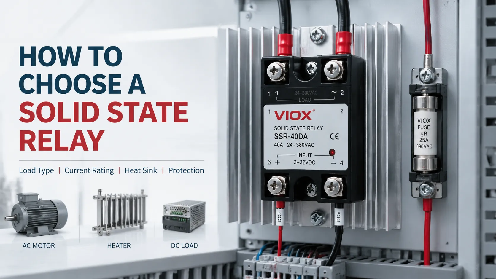
そのため、ソリッドステートリレー(SSR)の選定は、単なるカタログ番号の照合ではありません。信頼性の高い選定を行うには、以下の4つの技術的な問いに答える必要があります。
| 決定 | 何を確立すべきか |
|---|---|
| 1. SSRは電気的に適合しているか? | ACまたはDC出力、制御入力範囲、極性、電圧、周波数、相配置、およびスイッチングモード |
| 2. 負荷に耐えられるか? | 連続RMS電流、突入電流の大きさおよび持続時間、力率、スイッチング周波数、および過渡電圧 |
| 3. 設置場所で放熱は可能か? | 導通損失、盤内周囲温度、ディレーティング曲線、熱インターフェース、ヒートシンク、グループ化、および通風 |
| 4. 故障時には何が起こるか? | 漏れ電流、半導体ヒューズの協調、サージ抑制、過熱応答、および短絡故障後の安全なシャットダウン |
これら4つの決定事項を順に従ってください。負荷データや熱データが不足している場合に、汎用的な電流倍率を適用して補完しないでください。.
本ガイドは、産業用制御盤またはOEMアプリケーションを想定しています。製品定格、配線、保護協調、および熱設計は、正確なSSRデータシートおよび適用される機器規格に基づいて検証する必要があります。.
要点
- アン AC出力SSRは通常、DCをスイッチングできません, 。これは、トライアックまたはサイリスタ出力が電流のゼロクロスを利用してオフになるためです。DC出力SSRは通常MOSFETを使用しており、DCの極性と電圧に合わせて選択する必要があります。.
- 印刷されているSSRの電流値は条件付きの最大値であり、パネルで使用可能な電流を保証するものではありません。許容電流は、周囲温度の上昇やヒートシンクの性能低下に伴い、急激に減少する可能性があります。.
- 抵抗負荷電流のみでは、モーター、変圧器、ランプ、ソレノイド、または容量性負荷には不十分です。これらの始動電流やサージ持続時間が、選定の基準となることが一般的です。.
- ヒートシンクの選定は、以下に基づいて行う必要があります。 電力損失および接合部温度, 「負荷電流の2倍を使用する」といった一般的なルールに基づくべきではありません。“
- オフ状態は、回路の絶縁を意味するものではありません。SSRには残留電流があり、短絡故障する可能性があるため、メンテナンス時の唯一の遮断手段や安全絶縁装置として使用しないでください。.
- 分岐回路遮断器はケーブルを保護できても、半導体を保護できない場合があります。必要な場合は、高速半導体ヒューズとの協調を別途確認する必要があります。.
SSR選定の重要ポイント
| 選定項目 | 決定すべき事項 | 重要な理由 |
|---|---|---|
| 出力タイプ | AC、DC、またはAC/DC対応アーキテクチャ | 不適切な出力デバイスを使用すると、オフにならなかったり、直ちに損傷したりする可能性があります |
| 制御入力 | 入力電圧範囲、電流需要、極性 | 公称24 VのPLC出力は、実際の電圧降下条件下でもSSRを確実に駆動できなければなりません |
| 負荷カテゴリ | ヒーター、モーター、変圧器、ランプ、ソレノイド、LEDドライバー、コンデンサバンク | 各負荷は、それぞれ異なる突入電流、力率、およびスイッチングストレスを発生させます |
| 動作電圧 | 通常、最大、過渡、および周波数 | SSRは、定常電圧と繰り返される外乱の両方に耐えなければならない |
| 連続電流 | 最悪動作点におけるRMS電流 | 熱的選定の開始点を確立する |
| サージ電流 | ピーク値、波形、および持続時間 | 出力チップが始動時および故障時の過渡現象に耐えられるかを決定する |
| スイッチングモード | ゼロクロス、ランダムターンオン、または比例制御 | EMI、突入電流特性、および制御方法に影響します |
| 熱設計 | 電力損失、周囲温度、熱抵抗値、空気流 | 過度なジャンクション温度は、SSRの早期故障の主な原因です |
| オフ状態の動作 | 漏れ電流、dv/dt、最小負荷 | 小さな負荷では、発光、チャタリング、または通電状態が続いているように見えることがあります |
| 保護 | 半導体ヒューズ、MOV、スナバ、TVS、過熱トリップ | 異なるコンポーネントが、それぞれ異なる故障メカニズムに対応します |
基本的な内部構造と動作原理が最初に必要な場合は、以下をお読みください ソリッドステートリレーの理解. 本ページでは、一般的な定義の繰り返しではなく、サイジングと仕様に焦点を当てます。.
1. SSRを選択する前に負荷データを収集する
An SSR cannot be selected correctly from “230 V, 10 A” alone. Build a load profile with at least the following information:
- ACまたはDC電源(周波数および極性を含む)
- 単相または三相回路
- 公称電圧だけでなく、最大通常供給電圧
- 負荷電力または測定された定常状態のRMS電流
- 力率および該当する場合は効率
- 始動、充電、磁化、または冷フィラメント突入電流
- サージ持続時間および開閉頻度
- デューティサイクルと1時間あたりの予想起動回数
- 筐体内部の局所周囲温度
- 設置方向、換気、および隣接する熱源からの離隔距離
- 必要な制御方式:単純なオン/オフ、バースト制御、位相制御、または高速サイクル
- SSRが短絡故障した場合の結末
既存の機器については、電力ラベルのみに頼るよりも、測定された電流および突入電流の波形の方が通常は有用です。新規設計の場合は、一般的な乗数に頼るのではなく、負荷メーカーの最大電流および始動電流のデータを取得してください。.
通常負荷電流の推定
単相負荷の場合:
単相負荷電流の計算式
Iload = P ÷ (V × PF × η)
どこでだ:
- Iload: 負荷電流 (A)
- P: 電力 (W)
- V: 電圧 (V)
- PF: 力率
- η: 効率
平衡三相負荷の場合:
三相負荷電流の計算式
Iload = P ÷ (√3 × VLL × PF × η)
どこでだ:
- Iload: 負荷電流 (A)
- P: 電力 (W)
- VLL: 線間電圧 (V)
- PF: 力率
- η: 効率
抵抗加熱器の場合、力率と効率は多くの場合1に近くなります。モーターの場合は、銘板に記載されている電流値があればそれを使用してください。記載されている電力が機械的出力である場合は、効率を考慮する必要があります。.
2. 適切な出力技術の選択: AC SSRまたはDC SSR
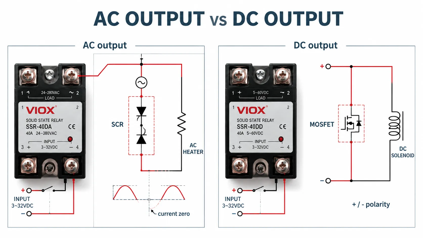
負荷電源が出力段を決定します。コントローラ電圧は決定しません。.
例えば、次のように記述されるリレーの場合: DC-to-AC 一般的に3-32 V DCの制御信号を受け入れますが、AC負荷を切り替えます。最初の用語は入力を、2番目の用語は出力を表します。.
| SSR出力 | 一般的な半導体 | 適切な負荷電源 | 重要な制限事項 |
|---|---|---|---|
| AC出力 | トライアックまたは逆並列接続されたSCR | AC負荷 | 負荷電流がゼロを通過する際に通常オフになります。一般的なDCスイッチングには適していません |
| DC出力 | MOSFET、特殊な設計ではIGBTを使用する場合もある | DC負荷 | 出力が明示的に双方向である場合を除き、極性に注意してください |
| 双方向DC出力 | バック・ツー・バック接続されたMOSFET | 逆阻止が必要なDC | 直列デバイスにより導通損失が増加する可能性がある |
| 三相AC出力 | 3極の制御されたAC出力 | 三相AC負荷 | すべての極について、熱的挙動および欠相挙動を評価しなければならない |
入力の説明から出力の互換性を推測してはならない。完全な型式、端子図、および出力仕様を確認すること。.
AC SSRでDCをスイッチングできるか?
通常はできません。トライアックやシリコン制御整流素子(SCR)は、電流が保持電流を上回っている間はオン状態を維持します。DCには自然な電流のゼロクロス点がないため、入力信号を除去した後もデバイスがオンのままになる可能性があります。.
DC SSRでACをスイッチングできますか?
出力が双方向電流用に特別に設計されている場合にのみ可能です。一般的な極性付きMOSFET出力は、AC SSRの代用にはなりません。.
3. PLC、コントローラ、またはセンサに制御入力を適合させる
一般的なSSR入力の表記である 3-32 V DC には、LEDと電流制限回路が含まれています。その広範なラベル表記だけでは、すべてのコントローラとの互換性が保証されるわけではありません。.
確認する:
- 保証ターンオン電圧および保証ターンオフ電圧
- 全電圧範囲における入力電流
- 入力極性
- コントローラ出力タイプ:ソース型、シンク型、リレー、トライアック、またはトランジスタ
- PLCのチャネルごとおよびコモングループごとの利用可能な出力電流
- 「オフ」時のコントローラからの残留電流または漏れ電流“
- 長い制御配線における電圧降下
- チャネル間および回路間に必要な絶縁
AC入力SSRについては、入力周波数、ピックアップ範囲、復帰電圧、および入力電流を確認してください。AC出力PLCや2線式センサは、感度の高いSSR入力をアクティブに保つのに十分な電流を漏らす可能性があります。適切に設計されたブリード回路またはインターフェースリレーが必要になる場合があります。.
4. 運転電流だけでなく負荷タイプで選定する
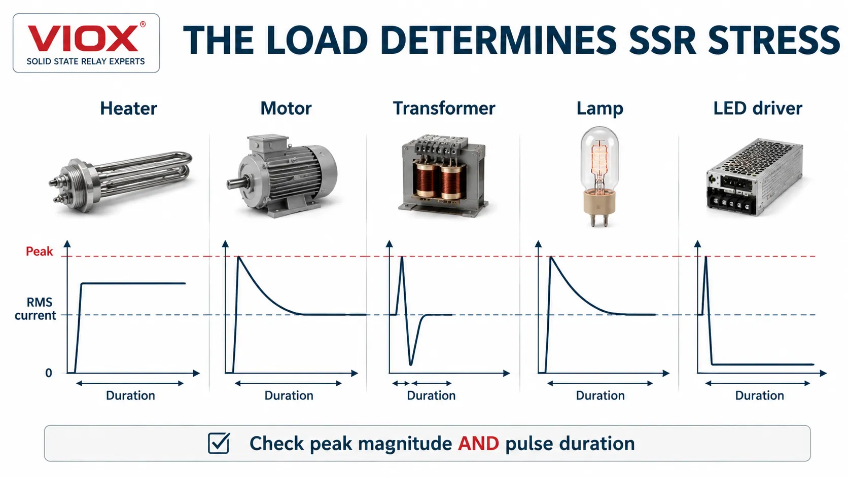
同じ10 Aの運転電流であっても、負荷によってかかるストレスは大きく異なります。.
| 負荷の種類 | 主な電気的ストレス | 選択の焦点 | 一般的なスイッチング手法 |
|---|---|---|---|
| 抵抗ヒーター | 連続電流と盤内発熱 | 実効電流、デューティサイクル、ヒートシンク | ゼロクロスは、オン/オフ制御やバースト制御で一般的に使用されます |
| モーターまたはコンプレッサー | 始動電流および拘束電流、頻繁なサイクル | モーター定格データ、始動時間、ストール保護、熱的余裕 | SSRメーカーのモーター負荷に関するガイダンスに従うこと |
| 変圧器 | 励磁突入電流は、スイッチング角および残留磁気に依存する | 変圧器固有のサージ曲線およびスイッチング方式 | 専用の定格ソリューションを使用すること。ゼロクロス制御が自動的に最適であると想定してはならない |
| ソレノイドまたはバルブ | 誘導遮断電圧 | サージ抑制および開放時間の要件 | コイルに適合したACまたはDC出力。適切な抑制回路を追加すること |
| 白熱灯または赤外線ランプ | 冷フィラメント突入電流 | 冷抵抗および繰り返しサージ耐量 | ゼロクロス制御はノイズを低減することが多いが、アプリケーションデータに従うこと |
| LEDドライバまたは容量性入力 | コンデンサ充電パルス、高い波高率、小さな定常電流 | ピーク電流、パルス持続時間、最小負荷、漏れ電流 | 容量性負荷のデータを使用してください。銘板のワット数だけでは不十分です。 |
抵抗加熱負荷
加熱負荷は通常、最も単純なSSRアプリケーションですが、長期間にわたって高いデューティサイクルで動作する可能性があります。このため、始動電流よりも導通損失と筐体温度が重要になります。最大ホット状態電流と、想定される最悪の供給電圧を使用してください。.
モーターおよびコンプレッサー
モーター用SSRのサイズを全負荷電流だけで決定しないでください。始動電流、加速時間、1時間あたりの始動回数、拘束回転子保護、欠相、および逆転や制動が必要かどうかを確認してください。汎用SSRのアンペア定格は、モーター利用定格と同等ではありません。.
ソフトスタート、電流制限、または制御された加速を必要とするアプリケーションでは、単純なオン/オフ制御のSSRよりも、半導体モーターコントローラーまたはソフトスターターの方が適切な場合があります。IEC 60947-4-2は、その適用範囲内で半導体モーターコントローラー、スターター、およびソフトスターターを規定しています。.
トランスフォーマー
トランスの励磁突入電流は、投入角、残留磁束、電源インピーダンス、およびトランスの設計に強く影響されます。電圧ゼロで正確に投入すると、一部のトランスアプリケーションでは深刻な磁束非対称が生じる可能性があります。トランス負荷に関する明確なガイダンスと、検証済みのサージ電流エンベロープを備えたSSRまたはコントローラーを選択してください。.
LEDドライバおよび容量性負荷
LED電源は、起動後にはわずか数分の1アンペアしか消費しない場合がありますが、起動時にはその数倍の短い充電パルスが発生することがあります。ドライバの突入電流の大きさとパルス幅を、SSRの繰り返しおよび非繰り返しサージデータと比較してください。また、オフ状態の漏れ電流が入力コンデンサを充電し、点滅の原因となる可能性があるため、併せて確認してください。.
5. 出力電圧および過渡マージンの確認
SSRの出力電圧定格は、開放された出力端子間に発生し得る最高の定常状態電圧を超えている必要があります。また、ラインの乱れ、誘導性スイッチング、および繰り返される過渡現象に耐えうるものでなければなりません。.
レビュー:
- 公称および最大連続供給電圧
- AC RMS定格とピーク阻止電圧の比較
- 直流最大動作電圧
- 繰り返しピークオフ状態電圧
- 静的および転流dv/dt
- サージ環境および上流側の保護
- 制御回路と負荷回路間の絶縁定格
すべてのSSR技術に対して一律の電圧マージン率を適用しないでください。メーカーのアプリケーション曲線を使用し、選択した金属酸化物バリスタ(MOV)、過渡電圧抑制(TVS)デバイス、またはSPDとSSRを調整してください。.
6. ディレーティング曲線からSSRの電流を決定する
SSRに印字されている電流値は、通常、規定の熱条件下で設定されています。これらの条件には、特定のケース温度、ヒートシンク、空気の流れ、取り付け方向、または周囲温度が含まれる場合があります。したがって、「40 A」のSSRであっても、密閉された高温の制御盤内では40 Aを連続して流すことができない可能性があります。.
正確なデータシートの曲線から許容電流係数を使用してください:
SSR定格電流選定式
ISSR,定格 ≥ Iload ÷ Fallowable
どこでだ:
- Iload:最大連続負荷電流
- Fallowable:許容電流係数
次の場合:
- I_{load}は最大連続RMS負荷電流です。;
- F_{allowable}は、実際の周囲環境および取り付け条件下における銘板電流の有効利用率です。.
データシートで設計条件における公称定格の50%しか許容されていない場合、18 Aの連続負荷に対しては、サージおよび負荷カテゴリの確認を行う前に、少なくとも36 Aの定格を持つSSRが必要です。これは普遍的な50%のディレーティングルールではなく、メーカーの曲線図を適用する方法の一例です。.
電流の選別だけで選定が完了するわけではありません。候補となる製品は、サージ電流、熱、スイッチング周波数、および保護協調の確認を通過する必要があります。.
ソリッドステートリレーの選定およびヒートシンク計算ツール
VIOXソリッドステートリレー選定およびヒートシンク計算ツールを使用して、必要なSSRの電流定格、導通損失、ヒートシンクの熱抵抗、接合部温度、サージマージン、オフ状態漏れ電流、および半導体ヒューズの予備的なI^2t協調を推定してください。.
実際の出力技術、負荷タイプ、システム電圧、電力または測定電流、力率、デューティサイクル、周囲温度、および候補となるSSRのデータシートから得られる熱パラメータを入力してください。.
[ここにVIOXソリッドステートリレー選定およびヒートシンク計算ツールを挿入]
予備選定のみ: この結果は、メーカーの正確なディレーティング曲線、負荷カテゴリ定格、サージ電流曲線、取り付け手順、熱インターフェース要件、または承認された半導体ヒューズ協調表に代わるものではありません。.
完全版のソリッドステートリレー選定およびヒートシンク計算ツールを開く
7. ゼロクロス型とランダムターンオン型SSRの比較
この選択は主にAC出力SSRに適用されます。.
ゼロクロススイッチング
ゼロクロスSSRは、AC電圧がゼロ付近になるまで待機してからオンになります。抵抗加熱やバースト制御において、任意の位相角でスイッチングする場合と比較して伝導妨害および放射妨害を低減できるため、広く使用されています。.
常に最適であるとは限りません。変圧器の励磁特性、モーターの始動、および特殊な制御方法については、用途に応じた検討が必要です。.
ランダムターンオンスイッチング
ランダムターンオンSSRは、入力指令と半導体の条件が許す限り、即座に導通を開始します。これは位相角電力制御や、コントローラーが点弧角を選択する必要がある用途で必須となります。.
| の応用 | 一般的な開始点 | 承認前の確認事項 |
|---|---|---|
| 抵抗ヒーター、単純なオン/オフ | ゼロクロス | サイクル周期、熱負荷、EMI要件 |
| ヒーター、位相制御 | ランダムターンオン | コントローラーの互換性、高調波、EMCフィルタリング |
| 変圧器 | 用途別SSR/コントローラー | 励磁突入電流、残留磁気、点弧方式 |
| モーター/コンプレッサー | モーター定格SSR | 始動/停止電流、スイッチングモード、1時間あたりの始動回数 |
| DC負荷 | DC出力SSR | ゼロクロスという用語は適用されません |
8. 単相SSRと三相SSRの比較
単相SSRは1つの制御電流経路を切り替えます。三相システムでは以下を使用する場合があります:
- 1つの統合型三相SSR;
- 3台の単相SSRをまとめて制御する場合、または
- 適用される設計で許可されている3線式回路において、2極を制御する場合。.
統合ユニットは取り付けと協調制御を簡素化しますが、その合計発熱量はかなりのものになる可能性があります。SSRを個別に配置すれば熱を分散でき交換も容易になりますが、設計においては同時指令、欠相検出、不均一な冷却、および共有ヒートシンクの温度管理を行う必要があります。.
モーターの場合、3台の独立した汎用SSRを完全なモーター始動器として扱わないでください。過負荷保護、短絡保護、欠相時の動作、再始動ロジック、および絶縁には、依然として協調のとれた設計が必要です。.
9. SSRの電力損失とヒートシンク要件の計算
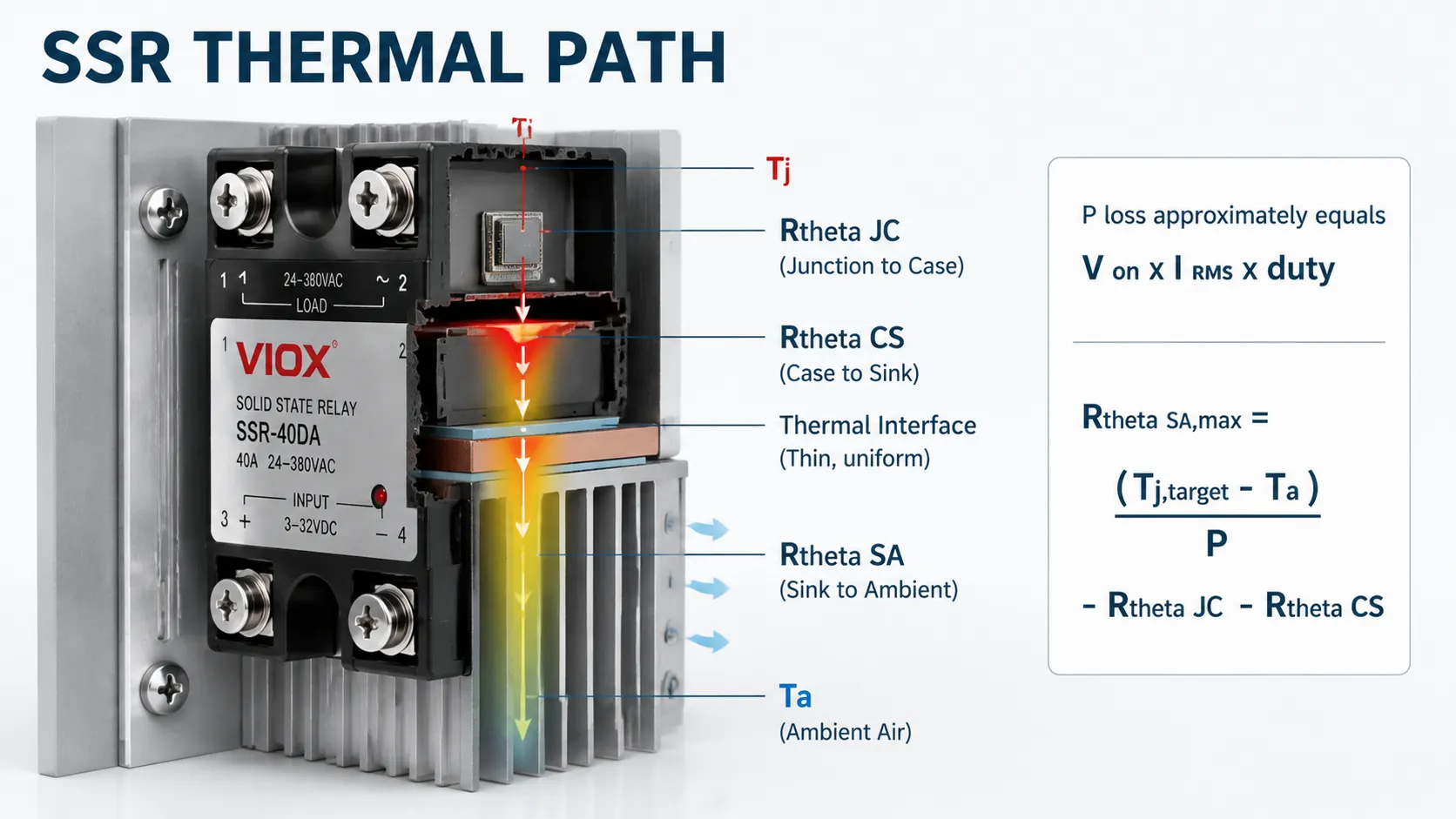
AC SSRの導通損失
オン状態電圧降下を用いた予備計算を行う場合:
AC SSRの導通損失計算式
Ppole ≈ VON × IRMS × D
どこでだ:
- VON: オン状態電圧降下
- IRMS: 実効電流
- D: デューティ比
ここでDはオンデューティ比です。メーカーが電力損失曲線を提供している場合は、電圧降下が完全に一定ではないため、その曲線を使用してください。.
DC MOSFET SSRの導通損失
MOSFET出力の場合:
DC MOSFET SSR損失計算式
Ppole ≈ IRMS² × RDS(on) × D
どこでだ:
- RDS(on): MOSFETオン抵抗
- D: デューティ比
低温時の代表値だけでなく、想定されるジャンクション温度におけるR_{DS(on)}を使用してください。MOSFETの抵抗値は一般的に温度上昇とともに増加します。.
ヒートシンクの熱抵抗
1つのヒートシンクに1つのSSRを取り付ける場合:
ヒートシンクの熱抵抗計算式
RθSA,max = (TJ,target − TA) ÷ P − RθJC − RθCS
どこでだ:
- TJ,target: 目標ジャンクション温度
- TA: 周囲温度
- P: SSR電力損失
次の場合:
- T_{J,target}は設計上のジャンクション温度制限であり、絶対最大定格未満に維持されます。;
- T_Aはヒートシンク周辺の局所的な空気温度です。;
- PはSSR電力損失です。;
- R_{\theta JC}はジャンクション・ケース間の熱抵抗です。;
- R_{\theta CS}はケース・シンク間の熱抵抗です。;
- R_{\theta SA}は、1ワットあたりの摂氏で表される、必要なヒートシンクから周囲への熱抵抗です。.
R_{\theta SA}が低いほど、ヒートシンクの効率が高いことを意味します。.
計算例
AC SSRが18 Aを連続して流し、オン状態電圧降下が1.6 Vであり、周囲温度が45 ℃に達する場所に設置されていると仮定します。.
P = 1.6 \times 18 = 28.8\ W
設計上の接合部温度を100 ℃、R_{\theta JC}=0.5 ℃/W、R_{\theta CS}=0.2 ℃/Wとした場合:
R_{\theta SA,max} = \frac{100-45}{28.8} – 0.5 – 0.2 \approx 1.21\ ^\circ C/W
選択するヒートシンクは、以下を提供する必要があります 1.21 ℃/W以下 実際の向き、筐体の通気、高度、および取り付け条件に基づきます。この例は説明用です。正確なSSRの損失データと熱抵抗を使用してください。.
1つのヒートシンクに複数のSSRを配置する場合
複数のモジュールでヒートシンクを共有する場合、各モジュールが独自のジャンクション・ケース間熱抵抗を保持しつつ、合計の熱によってシンク温度が上昇します:
SSRのジャンクション温度計算式
TJ = TA + Ptotal × RθSA + Pmodule × (RθJC + RθCS)
どこでだ:
- TJ:ジャンクション温度
- TA: 周囲温度
各SSRがヒートシンク全体を占有しているかのように計算しないでください。.
10. パネル温度、グループ化、および取り付けを考慮する
室温は設計上の周囲温度ではありません。パネルが熱平衡に達した後、SSRおよびヒートシンク入口付近の空気温度を測定または推定してください。.
SSRの温度を過小評価する一般的な原因は以下の通りです:
- 日光にさらされる密閉型エンクロージャ;;
- 自然対流が妨げられる場所に取り付けられたヒートシンク;;
- 近接してグループ化された複数のSSR、電磁接触器、または電源装置;;
- 上方への気流経路を形成できない水平フィン;;
- 高地、ダストフィルター、または強制空冷性能の低下;;
- 過剰または不適切に塗布されたサーマルコンパウンド、;
- 不均一な取り付け圧力、またはヒートシンク表面の歪み。.
SSRメーカーのトルク、平面度、サーマルパッド、および取り付けに関する指示に従ってください。サーマルコンパウンドは多ければ良いというものではありません。界面材料は、厚い絶縁層を形成することなく、微細な隙間を埋めるものであるべきです。.
一体型ヒートシンクか、それとも分離型ヒートシンクか?
DINレール一体型ヒートシンクを備えたSSRは、部品点数と組み立て時間を削減できます。一方、分離型ヒートシンクは、より大きな損失、共有熱負荷、空気流、および交換への対応において、設計者により大きな自由度を与えます。どちらの構造が本質的に優れているということはありません。.
| 構成 | 主な利点 | 主な制限事項 | 最適な評価方法 |
|---|---|---|---|
| 一体型ヒートシンク | コンパクトな組み立てと簡素化された設置 | 固定された冷却能力とDINレールゾーン内の過密化の可能性 | 実際の盤内周囲温度および間隔における許容電流を確認すること |
| 個別ヒートシンク | 熱抵抗、サイズ、および気流の選択肢が広い | 取り付け作業の増加とインターフェース品質への依存度の高まり | 完全な熱経路を計算し、ケース温度を検証すること |
| 共有ヒートシンク | 複数のSSRの盤内スペースを削減可能 | 各モジュールからの熱が共通のヒートシンク温度を上昇させます。 | 総熱損失と各モジュールの個別の接合部経路を合計して使用してください。 |
負荷電流のみに基づいてこれらのオプションを選択しないでください。同一の筐体条件下における接合部温度の余裕を比較してください。.
11. オフ状態の漏れ電流と最小負荷の理解
SSRは機械的なエアギャップのような動作はしません。オフ時には、その出力半導体および内部スナバ回路に微小な電流が流れます。.
この漏れ電流は以下のような原因となります:
- LEDランプの点灯や点滅;
- 高インピーダンスメーターにおける「ゴースト」電圧の表示;
- 小型ソレノイドが唸り音を立てたり、解放に失敗したりする原因となります。;
- 電子電源装置が周期的に充電および再起動を繰り返す原因となります。;
- トラブルシューティング中に負荷が通電状態であるように見える原因となります。.
SSRの最大オフ状態漏れ電流を、負荷の解放電流および最小動作電流と比較してください。メーカーが承認したブリード抵抗器を使用することで一部の小負荷の問題は解決できる可能性がありますが、発熱が増加するため、連続電圧および安全な放電に対して定格を満たす必要があります。外部RCスナバも漏れ電流を増加させる可能性があります。.
メンテナンス前には必ず絶縁を行い、電圧が存在しないことを確認してください。SSRのオフ指令は安全な絶縁方法ではありません。.
12. SSR周辺の保護の調整
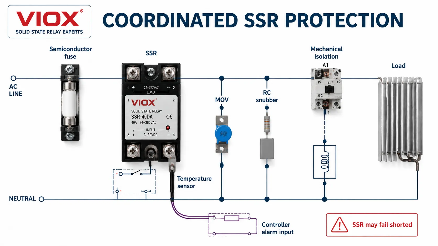
単一の保護コンポーネントですべてのSSRへのストレスに対処することはできません。.
| 保護対策 | 主な目的 | 選定時の注意 |
|---|---|---|
| 分岐回路遮断器または一般ヒューズ | ケーブルおよび回路保護 | 半導体接合部を保護するには動作が遅すぎる可能性がある |
| 高速半導体用ヒューズ | SSRを流れる故障エネルギーを制限する | SSRメーカーの協調表を使用するか、有効かつ共通の試験基準に基づいて比較すること |
| MOV | 繰り返し発生する過電圧または偶発的な過電圧をクランプする | MCOV、クランプ電圧、エネルギー、経年劣化、および追随電流を調整する |
| RCスナバ | AC誘導回路におけるdv/dtおよびリンギングを制限する | オフ状態の漏れ電流と熱を追加する |
| フライバックダイオード | DCコイルの誘導キックを抑制する | コイルの開放を遅らせるため、極性を正しくする必要がある |
| TVSダイオード | DC過渡電圧をより高い電圧でクランプする | フライバックダイオードよりも負荷の開放は速いが、ストレスは高い |
| サーマルスイッチまたはセンサー | ヒートシンクの過熱を検出します | 重要な熱経路を代表する場所に配置してください |
| 機械式電磁接触器/遮断器 | 絶縁または冗長シャットダウンを提供します | シーケンスおよび故障時の責務に合わせて調整する必要があります |
半導体ヒューズの協調
MCCBまたはMCBは、故障を遮断することはできますが、SSRを破壊するのに十分なエネルギーを通過させてしまう可能性があります。半導体保護が必要な場合は、SSRメーカーが推奨する超高速ヒューズを使用してください。.
予備的なパルスエネルギー比較には、以下を使用できます:
パルスエネルギーの推定
I²t ≈ Ipeak² × tpulse
どこでだ:
- Ipeak: ピーク電流
- tpulse: パルス持続時間
ただし、ヒューズの全遮断I^2tとSSRの耐量I^2tは、波形、持続時間、初期温度、システム電圧、および試験条件が適合している場合にのみ意味を持ちます。承認された協調表は、個別のカタログ番号の比較よりも強力な根拠となります。.
MOVおよびスナバの選定
MOVの最大連続動作電圧は、通常の最高線間電圧を上回る必要があり、その保護レベルはSSRの関連する過渡耐量を下回る必要があります。繰り返される過渡現象、電源インピーダンス、およびMOVの寿命末期の挙動も重要です。.
RCスナバは、過大なdv/dtや誘導性リンギングが誤点弧やデバイスへのストレスを招く恐れがある場合に有効です。オフ状態電流を増加させるため、自動的に追加するのではなく、回路の一部として設計する必要があります。.
固定されたトリップポイントだけでなく、温度の傾向を使用すること。
連続運転される機器や重要度の高い機器では、ヒートシンク温度センサーは緊急停止以上の役割を果たします。温度の傾向を負荷電流や盤内周囲温度と合わせて監視することで、SSRがトリップ閾値に達する前に、空気経路の閉塞、ファンの故障、ヒートシンクの汚れ、熱インターフェースの緩み、またはデューティサイクルの増加を明らかにできます。.
ヒートシンク温度の上昇は、SSR自体が故障している証拠ではありません。同様の負荷および周囲条件下での測定値を比較し、熱経路全体を調査してください。制御入力のみに接続されたサーマルスイッチでは、SSRが短絡故障した後に負荷を遮断することはできません。リスクアセスメントにより確実な遮断が求められる場合は、別途機械的な開閉装置または絶縁装置が必要です。.
13. 一般的なSSR故障モードに対する設計
パワー半導体はしばしば 短絡, 故障を起こします。特に過熱、サージ電流、過電圧、または不十分な故障エネルギー制限の後に発生しやすくなります。制御入力がオフであっても、負荷が通電状態のままになる可能性があります。.
| 症状 | 推定原因 | エンジニアリング上の対応 |
|---|---|---|
| 負荷が完全にオンのままになる | 出力半導体が短絡故障、配線のバイパス | 電源を遮断し、メーカーの試験方法に従って出力抵抗を確認し、SSRを交換し、熱およびサージの原因を調査する |
| 負荷がオンにならない | 出力の開放、入力駆動不足、ヒューズ溶断、負荷の故障 | 制御入力、出力電圧、ヒューズの導通、および負荷電流を安全に測定する |
| 冷間時は動作するが、熱間時に故障する | ヒートシンクの不備、接触不良、周囲温度の過昇、入力の余裕不足 | 熱安定化後のケース/ヒートシンク温度および電流を記録する |
| ヒューズの誤動作 | 負荷突入電流の過小評価、不適切なヒューズ、繰り返されるサージ | 突入電流波形をキャプチャし、ヒューズとSSRの協調を確認する |
| 誤点弧 | 過大なdv/dt、制御ノイズ、配線結合 | 配線経路、サプレッション、シールド、および入力ノイズマージンを改善する |
| オフ時に小型負荷が発光またはチャタリングする | 漏れ電流またはスナバ電流 | 負荷開放特性に対して最大漏れ電流を確認してください。承認されたブリード回路または異なる出力アーキテクチャを使用してください。 |
通電が継続することで火災、動作、圧力、またはプロセスの危険が生じる可能性がある場所では、安全状態の維持を1台のSSRに依存しないでください。リスクアセスメントの要求に従い、適切な機械的遮断器または安全定格アーキテクチャ、独立した過熱保護、および故障監視を使用してください。.
14. SSR調達仕様書
「40 A SSR、24 V入力」のような購入記述だけでは不十分です。サプライヤーおよび盤製作会社が実際の用途を評価できる仕様書を使用してください。.
| 仕様項目 | 要求または提供すべき情報 |
|---|---|
| の応用 | 負荷機器、開閉目的、デューティサイクル、1時間あたりの起動回数/サイクル数 |
| 入力 | 公称値/範囲、入力電流、ピックアップ/ドロップアウトレベル、極性、PLC出力タイプ |
| 出力技術 | ACトライアック/SCR、DC MOSFET、双方向DC、または統合型三相 |
| 負荷電源 | 公称電圧および最大電圧、周波数、相配置 |
| 負荷データ | RMS電流、力率、効率、突入波形、サージ持続時間 |
| スイッチングモード | ゼロクロス、ランダムターンオン、または比例制御器の互換性 |
| 電流容量 | 指定された周囲温度および取り付け条件における連続電流 |
| 熱データ | 電力損失曲線、V_{ON} または R_{DS(on)}、R_{\theta JC}、インターフェース要件、ディレーティング曲線 |
| オフ状態データ | 漏れ電流、最小負荷、阻止電圧、静的および転流 dv/dt |
| サージデータ | ピーク電流、波形、パルス持続時間、繰り返し制限、I^2t 基準 |
| 保護 | 認定半導体ヒューズ、MOV/スナバガイダンス、過熱保護オプション |
| メカニカル | パッケージ、端子、取り付け、ヒートシンク、トルク、タッチ保護 |
| ドキュメンテーション | データシート改訂、試験報告書、トレーサビリティ、適用認証エビデンス |
15. OEMおよび盤プロジェクト向けサプライヤー監査チェックリスト
SSRファミリーを承認する前に、サプライヤーに以下を提出させてください:
- 正確な取り付け配置における電流対周囲温度のディレーティング曲線;
- 意図する電流範囲全体における電力損失データ;
- ジャンクション・ケース間の熱抵抗およびインターフェースに関する指示;
- 波形および持続時間が明記されたサージ電流曲線;
- 推奨される高速ヒューズモデル、または文書化された協調手法;
- 動作温度における最大漏れ電流および最小負荷;
- dv/dtおよび過渡電圧データ、;
- 端子トルクおよび導体の要件、;
- ロット追跡可能性および変更管理プロセス、;
- 統計的工程管理が使用されるオフ状態漏れ電流、オン状態電圧降下、阻止電圧、入力ピックアップなどの重要特性に関する製造ロットデータ、;
- 主張される認証または規格適合の証拠、;
- 実際の組み立てにおける温度上昇、突入電流、漏れ電流、および故障応答の検証用サンプル。.
大量のOEM調達において、統計的能力データは、パラメータが単に仕様限界に合格しているだけでなく、一貫して制御されているかどうかを判断するのに役立ちます。サプライヤーがCpkなどの工程能力指数を報告する場合は、測定された特性、サンプルサイズ、管理限界、試験温度、およびロット期間を確認してください。その文脈のないCpk値は、SSRの信頼性を示す意味のある証拠にはなりません。.
IEC 62314:2022は、その適用範囲内にある全か無かのソリッドステートリレーの要件を規定しています。非モーター負荷用のAC半導体コントローラおよび電磁接触器はIEC 60947-4-3に該当し、半導体モーターコントローラおよびスタータはIEC 60947-4-2で扱われます。適用される製品および組み立て要件は、SSRがどのように供給および統合されるかによって異なります。コンポーネントの認証のみでは、完成したパネルを認証することにはなりません。.
16. SSR選定における一般的な誤り
銘板の電流値をそのまま使用可能なパネル電流として扱うこと
修正するには、正確なディレーティング曲線を使用し、最悪の周囲温度条件下でジャンクション温度を確認する必要があります。.
負荷の突入電流を無視すること
突入電流の波形を測定または入手してください。パルス持続時間のないピーク電流値だけでは不十分です。.
ゼロクロスが常に優れていると想定すること
ゼロクロスは多くの抵抗加熱用途において強力なデフォルト設定ですが、トランス、モーター、または位相制御に対する普遍的なルールではありません。.
SSRの定格電流でヒートシンクを選定すること
実際の半導体損失と完全な熱経路を計算してください。同じ電流定格を持つ2つのSSRであっても、電圧降下や熱的要件が異なる場合があります。.
SSRを保護するために汎用回路遮断器に頼ること
導体の保護と半導体接合部の保護は、別々の協調タスクです。.
「オフ」を絶縁状態として扱うこと
残留電流と短絡故障を考慮してください。安全な絶縁とリスクに応じた遮断経路を確保してください。.
回路の動作を確認せずにEMRを交換すること
SSRは残留電流、発熱、故障モード、電圧降下、および過渡特性を変化させます。技術の選択で迷っている場合は、以下を確認してください。 電磁リレーとソリッドステートリレーの比較 設計を最終決定する前に。.
よくある質問
SSRの定格電流は、大きいほど常に安全と言えますか?
必ずしもそうとは限りません。電流クラスが高いほど、通常はチップ面積や熱的余裕が大きくなりますが、その利点は内部設計、ヒートシンク、周囲温度、端子、サージ定格、および保護機能に依存します。過剰なサイズ選定では、不適切な出力技術や不十分な熱的実装を補うことはできません。.
2台のSSRを並列接続して電流を分担させることはできますか?
メーカーが明示的にサポートしていない限り、一般的なSSRの出力を並列接続しないでください。オン状態の電圧、温度、配線インピーダンスのわずかな違いにより、一方のデバイスに過大な電流が流れ、熱暴走を引き起こす可能性があります。適切に定格選定されたSSRを1台使用するか、メーカーが承認した並列アセンブリを使用してください。.
複数のSSRで1つのヒートシンクを共有できますか?
電気的クリアランス、絶縁、取り付け手順、および合計の熱計算が許容範囲内であれば可能です。モジュールの総損失を使用してヒートシンク温度を計算し、各SSR固有のジャンクション・ケース間およびケース・ヒートシンク間の温度上昇を加算してください。.
SSRがオフのときに負荷側で電圧が測定されるのはなぜですか?
半導体または内部スナバを介したオフ状態の漏れ電流により、特に高インピーダンスのデジタルメーターを使用した場合、メーターの読み値が発生することがあります。それが無害なゴースト電圧なのか、負荷を動作させるのに十分な電流なのかを判断してください。制御コマンドに基づいて回路が安全に触れられると決して判断しないでください。.
AC負荷に対してゼロクロスSSRが常に最適ですか?
いいえ。抵抗加熱器のスイッチングやバースト制御には一般的に推奨されますが、位相角制御にはランダムターンオンが必要です。変圧器やモーターの用途では、スイッチング角によって突入電流や電磁的ストレスが変化するため、負荷に応じたガイダンスが必要です。.
回路にすでに回路遮断器がある場合、なぜ半導体ヒューズを使用するのですか?
回路遮断器は主に配線を保護し、回路の故障を除去するためのものです。標準的な回路遮断器が開放される前に、半導体接合部が損傷する可能性があります。協調のとれた超高速ヒューズは、通過エネルギーをSSRが耐えられるレベルまで制限します。.
SSRにとってどの程度の温度が過熱となりますか?
信頼できる接触温度のルールはありません。メーカーの最大ケース温度または接合部温度を使用し、動作マージンを確保できる低い目標値で設計してください。パネルが定常状態に達した後、局所的な周囲温度、ケース温度、ヒートシンク温度、および電流を検証してください。.
最終選定ルール
信頼性の高いSSRは、カタログの電流値から選ぶのではなく、負荷から逆算して選定します。まずACまたはDCの出力技術と制御入力を一致させます。次に、負荷の突入電流、データシートのディレーティング、スイッチング方式、導通損失、接合部温度、漏れ電流特性、過渡保護、および故障応答に対してデバイスを評価してください。.
最適な調達記録とは、単に「SSR, 40 A」と記すことではありません。実際の負荷、周囲温度、ヒートシンク、サージプロファイル、保護装置、および出力が短絡故障した場合の安全な応答を示す動作点を文書化することです。.
技術リファレンス
- IEC 62314:2022 – 半導体リレー
- IEC 60947-4-2:2020+AMD1:2024 – 半導体モータコントローラ、スタータおよびソフトスタータ
- IEC 60947-4-3:2020 – 非モータ負荷用AC半導体コントローラおよび電磁接触器