ໃນໜ້ານີ້
ແຜ່ນຂໍ້ມູນ SSR ຈະບອກໃຫ້ທ່ານຮູ້ເຖິງແຮງດັນ ແລະ ກະແສໄຟຟ້າສູງສຸດພາຍໃຕ້ເງື່ອນໄຂການທົດສອບທີ່ກຳນົດໄວ້. ແຜງຄວບຄຸມຈະເພີ່ມເງື່ອນໄຂທີ່ມັກຈະເປັນຕົວຕັດສິນວ່າອຸປະກອນນັ້ນມີຄວາມໜ້າເຊື່ອຖືຫຼືບໍ່ ເຊັ່ນ: ກະແສໄຟຟ້າໃນຂະນະເລີ່ມຕົ້ນຂອງມໍເຕີ, ກະແສໄຟຟ້າກະຕຸ້ນໃນການສາກໄຟຂອງຄາປາຊິເຕີ, ຄວາມຮ້ອນທີ່ສະສົມຢູ່ພາຍໃນຕູ້ຄວບຄຸມ, ອຸປະກອນໄຟຟ້າທີ່ຕິດຕັ້ງຢູ່ໃກ້ກັນ, ແລະ ແຮງດັນກະຊາກທີ່ບໍ່ເຄີຍປາກົດຢູ່ໃນການຈັດອັນດັບໂຫຼດປົກກະຕິ.
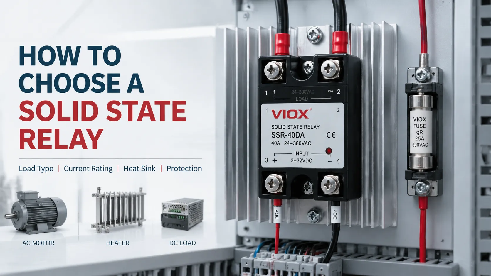
ນັ້ນຄືເຫດຜົນທີ່ວ່າການເລືອກໂຊລິດສະເຕດຣີເລ (SSR) ບໍ່ແມ່ນພຽງແຕ່ການເລືອກຕາມໝາຍເລກໃນລາຍການສິນຄ້າ. ການເລືອກທີ່ໜ້າເຊື່ອຖືຕ້ອງຕອບຄຳຖາມທາງວິສະວະກຳສີ່ຂໍ້:
| ການຕັດສິນໃຈ | ສິ່ງທີ່ຕ້ອງໄດ້ຮັບການກຳນົດ |
|---|---|
| 1. SSR ມີຄວາມເຂົ້າກັນໄດ້ທາງໄຟຟ້າຫຼືບໍ່? | ຜົນຜະລິດ AC ຫຼື DC, ຊ່ວງການປ້ອນຂໍ້ມູນຄວບຄຸມ, ຂົ້ວໄຟຟ້າ, ແຮງດັນ, ຄວາມຖີ່, ການຈັດລຽງເຟສ, ແລະ ຮູບແບບການສະຫຼັບ |
| 2. ມັນສາມາດທົນຕໍ່ໂຫຼດໄດ້ຫຼືບໍ່? | ກະແສ RMS ຕໍ່ເນື່ອງ, ຂະໜາດ ແລະ ໄລຍະເວລາຂອງກະແສໄຟຟ້າກະຊາກ (inrush), ຕົວປະກອບກຳລັງ (power factor), ຄວາມຖີ່ໃນການສະຫຼັບ, ແລະ ແຮງດັນຊົ່ວຄາວ |
| 3. ການຕິດຕັ້ງສາມາດລະບາຍຄວາມຮ້ອນອອກໄດ້ຫຼືບໍ່? | ການສູນເສຍຈາກການນຳຄວາມຮ້ອນ, ອຸນຫະພູມອາກາດລ້ອມຮອບຕູ້ຄວບຄຸມ, ເສັ້ນສະແດງການຫຼຸດຄ່າພິກັດ (derating curve), ຮອຍຕໍ່ລະບາຍຄວາມຮ້ອນ, ແຜ່ນລະບາຍຄວາມຮ້ອນ, ການຈັດກຸ່ມ, ແລະ ການໄຫຼວຽນຂອງອາກາດ |
| 4. ຈະເກີດຫຍັງຂຶ້ນໃນລະຫວ່າງທີ່ເກີດຄວາມຜິດພາດ? | ກະແສຮົ່ວໄຫຼ, ການປະສານງານລະຫວ່າງອຸປະກອນເຄິ່ງຕົວນຳກັບຟິວ, ການປ້ອງກັນກະແສເກີນຊົ່ວຄາວ, ການຕອບສະໜອງຕໍ່ອຸນຫະພູມເກີນ, ແລະ ການປິດລະບົບຢ່າງປອດໄພຫຼັງຈາກເກີດຄວາມຜິດພາດແບບວົງຈອນສັ້ນທີ່ຜົນຜະລິດ |
ໃຫ້ປະຕິບັດຕາມການຕັດສິນໃຈທັງສີ່ຂໍ້ນັ້ນຕາມລຳດັບ. ຢ່າຊົດເຊີຍຂໍ້ມູນໂຫຼດ ຫຼື ຂໍ້ມູນຄວາມຮ້ອນທີ່ຂາດຫາຍໄປໂດຍການໃຊ້ຕົວຄູນກະແສໄຟຟ້າແບບທົ່ວໄປ.
ຄູ່ມືນີ້ສົມມຸດວ່າເປັນການນຳໃຊ້ໃນຕູ້ຄວບຄຸມອຸດສາຫະກຳ ຫຼື OEM. ຄ່າພິກັດຂອງຜະລິດຕະພັນ, ການເດີນສາຍໄຟ, ການປະສານງານດ້ານການປ້ອງກັນ, ແລະ ການອອກແບບລະບົບຄວາມຮ້ອນຈະຕ້ອງໄດ້ຮັບການກວດສອບກັບແຜ່ນຂໍ້ມູນ SSR ທີ່ແນ່ນອນ ແລະ ມາດຕະຖານອຸປະກອນທີ່ກ່ຽວຂ້ອງ.
Key Takeaways
- ອັນ SSR ຜົນຜະລິດ AC ໂດຍປົກກະຕິບໍ່ສາມາດສະຫຼັບ DC ໄດ້, ເນື່ອງຈາກຜົນຜະລິດແບບ triac ຫຼື thyristor ຕ້ອງອາໄສການຂ້າມສູນຂອງກະແສໄຟຟ້າເພື່ອປິດການເຮັດວຽກ. SSR ຜົນຜະລິດ DC ໂດຍປົກກະຕິຈະໃຊ້ MOSFET ແລະ ຕ້ອງຖືກເລືອກໃຫ້ເໝາະສົມກັບຂົ້ວໄຟຟ້າ DC ແລະ ແຮງດັນໄຟຟ້າ.
- ກະແສໄຟຟ້າຂອງ SSR ທີ່ພິມໄວ້ແມ່ນຄ່າສູງສຸດຕາມເງື່ອນໄຂ ບໍ່ແມ່ນກະແສໄຟຟ້າທີ່ຮັບປະກັນວ່າສາມາດໃຊ້ງານໄດ້ໃນແຜງຄວບຄຸມ. ກະແສໄຟຟ້າທີ່ອະນຸຍາດໃຫ້ໃຊ້ໄດ້ອາດຫຼຸດລົງຢ່າງວ່ອງໄວເມື່ອອຸນຫະພູມອາກາດລ້ອມຮອບສູງຂຶ້ນ ຫຼື ປະສິດທິພາບຂອງແຜ່ນລະບາຍຄວາມຮ້ອນຫຼຸດລົງ.
- ກະແສໄຟຟ້າຂອງໂຫຼດປະເພດຄວາມຕ້ານທານພຽງຢ່າງດຽວບໍ່ພຽງພໍສຳລັບໂຫຼດປະເພດມໍເຕີ, ໝໍ້ແປງ, ຫຼອດໄຟ, ໂຊລີນອຍ ຫຼື ໂຫຼດປະເພດຄາປາຊີເຕີ. ກະແສໄຟຟ້າຂະນະເລີ່ມຕົ້ນ ແລະ ໄລຍະເວລາຂອງກະແສໄຟຟ້າກະຊາກມັກຈະເປັນຕົວຄວບຄຸມການເລືອກອຸປະກອນ.
- ການເລືອກແຜ່ນລະບາຍຄວາມຮ້ອນຄວນອີງໃສ່ ການສູນເສຍພະລັງງານ ແລະ ອຸນຫະພູມຈຸດຕໍ່ເຊື່ອມ, ບໍ່ແມ່ນກົດທົ່ວໄປເຊັ່ນ “ໃຫ້ໃຊ້ກະແສໄຟຟ້າສອງເທົ່າຂອງໂຫຼດ.”
- ສະຖານະປິດ (Off-state) ບໍ່ໄດ້ໝາຍເຖິງການຕັດວົງຈອນແບບເປີດວົງຈອນ. SSR ມີກະແສໄຟຟ້າຮົ່ວໄຫຼ ແລະ ສາມາດເກີດການລັດວົງຈອນໄດ້, ດັ່ງນັ້ນຈຶ່ງບໍ່ຄວນໃຊ້ເປັນອຸປະກອນຕັດການເຊື່ອມຕໍ່ເພື່ອບຳລຸງຮັກສາ ຫຼື ອຸປະກອນຕັດແຍກເພື່ອຄວາມປອດໄພພຽງຢ່າງດຽວ.
- ເບຣກເກີວົງຈອນຍ່ອຍອາດປ້ອງກັນສາຍໄຟໄດ້ໂດຍບໍ່ໄດ້ປ້ອງກັນອຸປະກອນສານກຶ່ງຕົວນຳ. ການປະສານງານຂອງຟິວສ໌ສຳລັບສານກຶ່ງຕົວນຳແບບໄວຕ້ອງໄດ້ຮັບການກວດສອບແຍກຕ່າງຫາກເມື່ອມີຄວາມຈຳເປັນ.
ປະເດັນສຳຄັນໃນການເລືອກ SSR
| ລາຍການທີ່ເລືອກ | ສິ່ງທີ່ຕ້ອງກຳນົດ | ເປັນຫຍັງມັນຈຶ່ງສໍາຄັນ |
|---|---|---|
| ປະເພດຜົນຜະລິດ | ສະຖາປັດຕະຍະກຳແບບ AC, DC, ຫຼື AC/DC | ອຸປະກອນຜົນຜະລິດທີ່ບໍ່ເໝາະສົມອາດຈະບໍ່ປິດການເຮັດວຽກ ຫຼື ອາດຈະເສຍຫາຍໃນທັນທີ |
| ການປ້ອນຂໍ້ມູນຄວບຄຸມ (Control input) | ຊ່ວງແຮງດັນໄຟຟ້າຂາເຂົ້າ, ຄວາມຕ້ອງການກະແສໄຟຟ້າ, ຂົ້ວໄຟຟ້າ | ຜົນຜະລິດ PLC ຂະໜາດ 24 V ທີ່ເປັນຄ່າລະບຸຕ້ອງສາມາດຂັບ SSR ໄດ້ຢ່າງໜ້າເຊື່ອຖືພາຍໃຕ້ເງື່ອນໄຂການຕົກຂອງແຮງດັນໄຟຟ້າຕົວຈິງ |
| ປະເພດຂອງໂຫຼດ (Load category) | ເຄື່ອງທຳຄວາມຮ້ອນ, ມໍເຕີ, ໝໍ້ແປງໄຟຟ້າ, ຫຼອດໄຟ, ໂຊລີນອຍ, ໄດເວີ LED, ທະນາຄານຄາປາຊິເຕີ | ໂຫຼດແຕ່ລະຊະນິດຈະສ້າງກະແສໄຟຟ້າກະຊາກ, ຕົວປະກອບກຳລັງ, ແລະ ຄວາມຄຽດໃນການສະຫຼັບວົງຈອນທີ່ແຕກຕ່າງກັນ |
| ແຮງດັນປະຕິບັດງານ | ປົກກະຕິ, ສູງສຸດ, ຊົ່ວຄາວ, ແລະ ຄວາມຖີ່ | SSR ຕ້ອງທົນທານຕໍ່ທັງແຮງດັນຄົງທີ່ ແລະ ການລົບກວນທີ່ເກີດຂຶ້ນຊ້ຳໆ |
| ກະແສໄຟຟ້າຕໍ່ເນື່ອງ | ກະແສ RMS ທີ່ຈຸດປະຕິບັດງານທີ່ຮ້າຍແຮງທີ່ສຸດ | ກຳນົດຈຸດເລີ່ມຕົ້ນສຳລັບການເລືອກທາງຄວາມຮ້ອນ |
| ກະແສກະຊາກ | ຂະໜາດສູງສຸດ, ຮູບຮ່າງຄື້ນ, ແລະ ໄລຍະເວລາ | ກຳນົດວ່າຊິບຜົນຜະລິດຈະລອດພົ້ນຈາກການເລີ່ມຕົ້ນ ແລະ ຄວາມຜິດປົກກະຕິຊົ່ວຄາວຫຼືບໍ່ |
| ໂໝດການສະຫຼັບ | ການຕັດຕໍ່ໄຟຟ້າເມື່ອແຮງດັນເປັນສູນ (Zero-cross), ການເປີດແບບສຸ່ມ (random turn-on), ຫຼື ການຄວບຄຸມແບບອັດຕາສ່ວນ | ສົ່ງຜົນກະທົບຕໍ່ EMI, ພຶດຕິກຳກະແສໄຟຟ້າກະຊາກ (inrush), ແລະ ວິທີການຄວບຄຸມ |
| ການອອກແບບຄວາມຮ້ອນ | ການສູນເສຍພະລັງງານ, ອຸນຫະພູມອາກາດລ້ອມຮອບ, ຄ່າ R-theta, ການໄຫຼວຽນຂອງອາກາດ | ອຸນຫະພູມຈຸດຕໍ່ (junction temperature) ທີ່ສູງເກີນໄປແມ່ນສາເຫດຫຼັກທີ່ເຮັດໃຫ້ SSR ເສຍຫາຍກ່ອນກຳນົດ |
| ພຶດຕິກຳໃນສະພາວະປິດ (Off-state) | ກະແສໄຟຟ້າຮົ່ວໄຫຼ, dv/dt, ໂຫຼດຂັ້ນຕໍ່າ | ໂຫຼດຂະໜາດນ້ອຍອາດຈະມີແສງສະຫວ່າງ, ສັ່ນ, ຫຼື ເບິ່ງຄືວ່າໄຟຍັງຈ່າຍຢູ່ |
| ການປົກປ້ອງ | ຟິວສ໌ສຳລັບອຸປະກອນກຶ່ງຕົວນຳ (Semiconductor fuse), MOV, ສະນັບເບີ (snubber), TVS, ການຕັດວົງຈອນເມື່ອອຸນຫະພູມສູງເກີນ | ອົງປະກອບທີ່ແຕກຕ່າງກັນຈະແກ້ໄຂກົນໄກການຂັດຂ້ອງທີ່ແຕກຕ່າງກັນ |
ຖ້າທ່ານຕ້ອງການໂຄງສ້າງພາຍໃນພື້ນຖານ ແລະ ຫຼັກການເຮັດວຽກກ່ອນ, ໃຫ້ອ່ານ ຄວາມເຂົ້າໃຈກ່ຽວກັບໂຊລິດສະເຕດຣີເລ (Solid State Relays). ໜ້ານີ້ເນັ້ນໃສ່ການກຳນົດຂະໜາດ ແລະ ຂໍ້ມູນຈຳເພາະ ຫຼາຍກວ່າການເວົ້າຊ້ຳຄຳນິຍາມທົ່ວໄປ.
1. ເກັບກຳຂໍ້ມູນໂຫຼດກ່ອນການເລືອກ SSR
SSR ບໍ່ສາມາດຖືກເລືອກໄດ້ຢ່າງຖືກຕ້ອງຈາກ “230 V, 10 A” ພຽງຢ່າງດຽວ. ໃຫ້ສ້າງໂປຣໄຟລ໌ໂຫຼດທີ່ມີຂໍ້ມູນຢ່າງໜ້ອຍດັ່ງຕໍ່ໄປນີ້:
- ການສະໜອງໄຟ AC ຫຼື DC, ລວມທັງຄວາມຖີ່ ແລະ ຂົ້ວໄຟຟ້າ
- ວົງຈອນເຟສດຽວ ຫຼື ສາມເຟສ
- ແຮງດັນໄຟຟ້າສະໜອງປົກກະຕິສູງສຸດ, ບໍ່ແມ່ນພຽງແຕ່ແຮງດັນໄຟຟ້າລະບຸ
- ກຳລັງໄຟຟ້າຂອງໂຫຼດ ຫຼື ກະແສໄຟຟ້າ RMS ສະພາວະຄົງທີ່ທີ່ວັດແທກໄດ້
- ຕົວປະກອບກຳລັງ (Power factor) ແລະ ປະສິດທິພາບ ໃນກໍລະນີທີ່ກ່ຽວຂ້ອງ
- ກະແສໄຟຟ້າກະຊາກໃນຂະນະເລີ່ມຕົ້ນ, ການສາກ, ການເຮັດໃຫ້ເກີດສະໜາມແມ່ເຫຼັກ, ຫຼື ກະແສໄຟຟ້າໃນຂະນະໄສ້ຫຼອດເຢັນ
- ໄລຍະເວລາຂອງກະແສໄຟຟ້າກະຊາກ ແລະ ຄວາມຖີ່ໃນການສະຫຼັບ
- Duty cycle ແລະ ຈໍານວນການເລີ່ມຕົ້ນທີ່ຄາດໄວ້ຕໍ່ຊົ່ວໂມງ
- ອຸນຫະພູມອາກາດພາຍໃນຕູ້ຄວບຄຸມ
- ທິດທາງການຕິດຕັ້ງ, ການລະບາຍອາກາດ, ແລະ ໄລຍະຫ່າງຈາກແຫຼ່ງຄວາມຮ້ອນທີ່ຢູ່ໃກ້ຄຽງ
- ວິທີການຄວບຄຸມທີ່ຕ້ອງການ: ການເປີດ/ປິດແບບງ່າຍດາຍ, ການຈ່າຍໄຟແບບເປັນຊຸດ (burst firing), ການຄວບຄຸມມຸມເຟສ (phase-angle control), ຫຼື ການສະຫຼັບວົງຈອນຢ່າງໄວວາ
- ຜົນສະທ້ອນຂອງ SSR ທີ່ເກີດການລັດວົງຈອນ
ສຳລັບອຸປະກອນທີ່ມີຢູ່ແລ້ວ, ການວັດແທກກະແສໄຟຟ້າ ແລະ ຮູບຄື້ນຂອງກະແສໄຟຟ້າຂະນະເລີ່ມຕົ້ນ (inrush) ມັກຈະມີປະໂຫຍດຫຼາຍກວ່າການເບິ່ງປ້າຍກຳກັບພະລັງງານພຽງຢ່າງດຽວ. ສຳລັບການອອກແບບໃໝ່, ໃຫ້ຂໍຂໍ້ມູນກະແສໄຟຟ້າສູງສຸດ ແລະ ກະແສໄຟຟ້າຂະນະເລີ່ມຕົ້ນຈາກຜູ້ຜະລິດໂຫຼດ ແທນທີ່ຈະອີງໃສ່ຕົວຄູນທົ່ວໄປ.
ການຄາດຄະເນກະແສໄຟຟ້າໂຫຼດປົກກະຕິ
ສຳລັບໂຫຼດເຟດດຽວ:
ສູດຄິດໄລ່ກະແສໄຟຟ້າໂຫຼດເຟດດຽວ
Iload = P ÷ (V × PF × η)
ບ່ອນທີ່:
- Iload: ກະແສໄຟຟ້າໂຫຼດ (A)
- P: ພະລັງງານ (W)
- V: ແຮງດັນໄຟຟ້າ (V)
- PF: ຕົວປະກອບກຳລັງ (Power factor)
- η: ປະສິດທິພາບ
ສຳລັບໂຫຼດສາມເຟສທີ່ສົມດູນ:
ສູດຄຳນວນກະແສໄຟຟ້າໂຫຼດສາມເຟສ
Iload = P ÷ (√3 × VLL × PF × η)
ບ່ອນທີ່:
- Iload: ກະແສໄຟຟ້າໂຫຼດ (A)
- P: ພະລັງງານ (W)
- VLL: ແຮງດັນໄຟຟ້າລະຫວ່າງສາຍ (V)
- PF: ຕົວປະກອບກຳລັງ (Power factor)
- η: ປະສິດທິພາບ
ສຳລັບເຄື່ອງເຮັດຄວາມຮ້ອນແບບຕ້ານທານ, ຕົວປະກອບກຳລັງ ແລະ ປະສິດທິພາບມັກຈະໃກ້ຄຽງກັບ 1. ສຳລັບມໍເຕີ, ໃຫ້ໃຊ້ຄ່າກະແສໄຟຟ້າທີ່ລະບຸໄວ້ໃນແຜ່ນປ້າຍຊື່ (nameplate) ຖ້າມີ. ຖ້າກຳລັງໄຟຟ້າທີ່ລະບຸໄວ້ເປັນກຳລັງຜົນຜະລິດທາງກົນຈັກ, ຈະຕ້ອງນຳເອົາປະສິດທິພາບມາຄິດໄລ່ຮ່ວມນຳ.
2. ເລືອກເທັກໂນໂລຊີຜົນຜະລິດທີ່ຖືກຕ້ອງ: AC SSR ຫຼື DC SSR
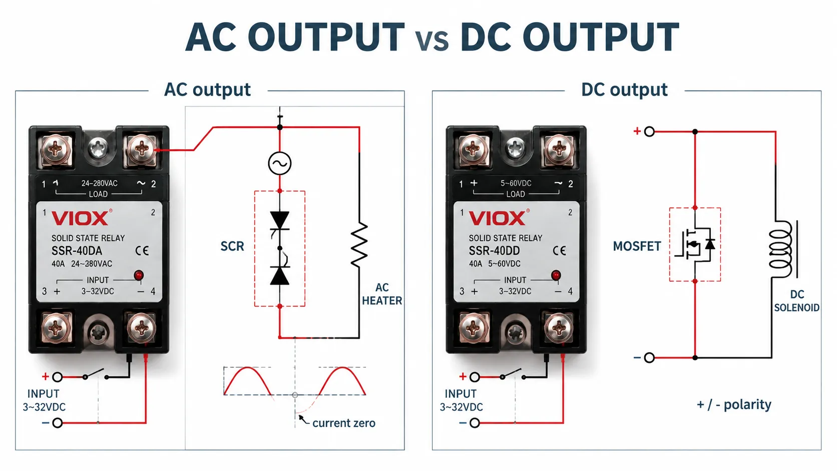
ການສະໜອງໂຫຼດເປັນຕົວການກຳນົດຂັ້ນຕອນຜົນຜະລິດ, ສ່ວນແຮງດັນຂອງຕົວຄວບຄຸມບໍ່ໄດ້ເປັນຕົວການກຳນົດ.
ຕົວຢ່າງເຊັ່ນ, ຣີເລທີ່ຖືກອະທິບາຍວ່າເປັນ DC-to-AC ໂດຍທົ່ວໄປແລ້ວຈະຮັບສັນຍານຄວບຄຸມຂະໜາດ 3-32 V DC ແຕ່ຈະສະຫຼັບໂຫຼດໄຟຟ້າ AC. ຄຳສັບທຳອິດອະທິບາຍເຖິງອິນພຸດ; ຄຳສັບທີສອງອະທິບາຍເຖິງເອົາພຸດ.
| ເອົາພຸດຂອງ SSR | ເຊມິຄອນດັກເຕີທົ່ວໄປ | ການສະໜອງໂຫຼດທີ່ເໝາະສົມ | ຂໍ້ຈຳກັດທີ່ສຳຄັນ |
|---|---|---|---|
| ເອົາພຸດ AC | Triac ຫຼື SCR ທີ່ຕໍ່ຂະໜານແບບປີ້ນກັບ | ໂຫຼດ AC | ປົກກະຕິຈະປິດເມື່ອກະແສໄຟຟ້າຂອງໂຫຼດຜ່ານຈຸດສູນ; ບໍ່ເໝາະສົມສຳລັບການສະຫຼັບໄຟຟ້າ DC ທົ່ວໄປ |
| ໄຟຟ້າກະແສກົງຂາອອກ | MOSFET, ບາງຄັ້ງໃຊ້ IGBT ໃນການອອກແບບສະເພາະ | ໂຫຼດ DC | ໃຫ້ສັງເກດຂົ້ວໄຟຟ້າ ເວັ້ນເສຍແຕ່ວ່າຜົນຜະລິດຈະເປັນແບບສອງທິດທາງຢ່າງຊັດເຈນ |
| ຜົນຜະລິດ DC ແບບສອງທິດທາງ | MOSFET ແບບຕໍ່ຫຼັງຊົນຫຼັງ | DC ໃນກໍລະນີທີ່ຕ້ອງການການປ້ອງກັນການໄຫຼຍ້ອນກັບ | ການສູນເສຍພະລັງງານໃນຂະນະນຳກະແສອາດຈະສູງຂຶ້ນເນື່ອງຈາກອຸປະກອນທີ່ຕໍ່ອະນຸກົມກັນ |
| ຜົນຜະລິດ AC ສາມເຟສ | ຂົ້ວຕໍ່ຜົນຜະລິດ AC ແບບຄວບຄຸມສາມຂົ້ວ | ໂຫຼດ AC ສາມເຟສ | ຕ້ອງມີການປະເມີນພຶດຕິກຳດ້ານຄວາມຮ້ອນ ແລະ ການຂາດເຟສສຳລັບທຸກຂົ້ວຕໍ່ |
ຢ່າໃຊ້ຄຳອະທິບາຍດ້ານອິນພຸດເພື່ອຄາດເດົາຄວາມເຂົ້າກັນໄດ້ຂອງເອົາພຸດ. ໃຫ້ອ່ານການລະບຸ, ແຜນວາດຂົ້ວຕໍ່ ແລະ ຂໍ້ມູນຈຳເພາະຂອງເອົາພຸດໃຫ້ຄົບຖ້ວນ.
AC SSR ສາມາດສະຫຼັບ DC ໄດ້ຫຼືບໍ່?
ໂດຍປົກກະຕິແລ້ວແມ່ນບໍ່. Triac ຫຼື silicon-controlled rectifier (SCR) ຈະຍັງຄົງເຮັດວຽກຢູ່ຕາບໃດທີ່ກະແສໄຟຟ້າຍັງສູງກວ່າກະແສໄຟຟ້າທີ່ຮັກສາສະຖານະ (holding current) ຂອງມັນ. DC ບໍ່ມີຈຸດຕັດສູນຂອງກະແສໄຟຟ້າຕາມທຳມະຊາດ, ດັ່ງນັ້ນອຸປະກອນອາດຈະຍັງຄົງເປີດຢູ່ຫຼັງຈາກທີ່ສັນຍານຂາເຂົ້າຖືກຕັດອອກ.
DC SSR ສາມາດສະຫຼັບ AC ໄດ້ບໍ?
ໄດ້ກໍຕໍ່ເມື່ອຜົນຜະລິດ (output) ຂອງມັນຖືກອອກແບບມາໂດຍສະເພາະສຳລັບກະແສໄຟຟ້າສອງທິດທາງ. MOSFET output ແບບມີຂົ້ວທົ່ວໄປບໍ່ສາມາດໃຊ້ແທນ AC SSR ໄດ້.
3. ຈັບຄູ່ Control Input ໃຫ້ເຂົ້າກັບ PLC, Controller, ຫຼື Sensor
SSR input ທົ່ວໄປທີ່ລະບຸວ່າ 3-32 V DC ລວມມີ LED ແລະວົງຈອນຈຳກັດກະແສໄຟຟ້າ. ປ້າຍກຳກັບທີ່ກວ້າງໆນັ້ນຍັງບໍ່ໄດ້ເປັນການຢືນຢັນເຖິງຄວາມເຂົ້າກັນໄດ້ກັບທຸກ Controller.
ຢືນຢັນ:
- ແຮງດັນໄຟຟ້າຂາເຂົ້າທີ່ຮັບປະກັນການເປີດ ແລະ ແຮງດັນໄຟຟ້າຂາເຂົ້າທີ່ຮັບປະກັນການປິດ
- ກະແສໄຟຟ້າຂາເຂົ້າຕະຫຼອດຊ່ວງແຮງດັນໄຟຟ້າ
- ຂົ້ວໄຟຟ້າຂາເຂົ້າ
- ປະເພດຜົນຜະລິດຂອງຄອນໂທຣເລີ: sourcing, sinking, ຣີເລ, triac, ຫຼື ທຣານຊິດເຕີ
- ກະແສໄຟຟ້າຜົນຜະລິດຂອງ PLC ທີ່ສາມາດໃຊ້ໄດ້ຕໍ່ແຊນເນວ ແລະ ຕໍ່ກຸ່ມ COM
- ກະແສຕົກຄ້າງ ຫຼື ກະແສຮົ່ວໄຫຼຈາກຄອນໂທຣເລີໃນເວລາ “ປິດ”
- ແຮງດັນຕົກໃນສາຍໄຟຄວບຄຸມທີ່ມີຄວາມຍາວ
- ການແຍກວົງຈອນທີ່ຈຳເປັນລະຫວ່າງແຊນເນວ ແລະ ວົງຈອນຕ່າງໆ
ສຳລັບ SSR ທີ່ໃຊ້ໄຟຟ້າ AC ຂາເຂົ້າ, ໃຫ້ກວດສອບຄວາມຖີ່ຂາເຂົ້າ, ຊ່ວງການເຮັດວຽກ (pickup range), ແຮງດັນໃນການປ່ອຍ (release voltage), ແລະ ກະແສໄຟຟ້າຂາເຂົ້າ. PLC ຜົນຜະລິດ AC ຫຼື ເຊັນເຊີສອງສາຍອາດມີກະແສຮົ່ວໄຫຼພຽງພໍທີ່ຈະເຮັດໃຫ້ອິນພຸດຂອງ SSR ທີ່ມີຄວາມລະອຽດອ່ອນຍັງຄົງເຮັດວຽກຢູ່; ອາດຈຳເປັນຕ້ອງມີການອອກແບບວົງຈອນ bleed network ຫຼື ຣີເລອິນເຕີເຟສຢ່າງເໝາະສົມ.
4. ເລືອກຕາມປະເພດໂຫຼດ ບໍ່ແມ່ນພຽງແຕ່ກະແສໄຟຟ້າຂະນະເຮັດວຽກ
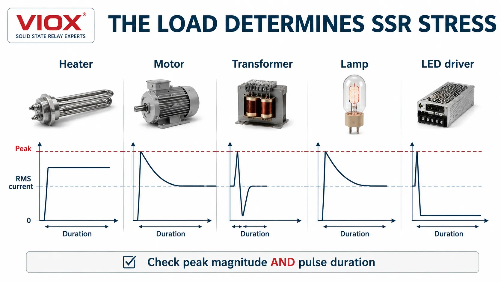
ກະແສໄຟຟ້າຂະນະເຮັດວຽກ 10 A ດຽວກັນ ສາມາດສ້າງຄວາມເຄັ່ງຕຶງທີ່ແຕກຕ່າງກັນຫຼາຍ ຂຶ້ນຢູ່ກັບປະເພດຂອງໂຫຼດ.
| ປະເພດການໂຫຼດ | ຄວາມເຄັ່ງຕຶງທາງໄຟຟ້າຫຼັກ | ຈຸດສຸມການຄັດເລືອກ | ວິທີການສະຫຼັບໄຟຟ້າທົ່ວໄປ |
|---|---|---|---|
| ເຄື່ອງເຮັດຄວາມຮ້ອນແບບຄວາມຕ້ານທານ | ກະແສໄຟຟ້າຕໍ່ເນື່ອງ ແລະ ຄວາມຮ້ອນໃນຕູ້ຄວບຄຸມ | ກະແສ RMS, ຮອບວຽນການເຮັດວຽກ, ແຜ່ນລະບາຍຄວາມຮ້ອນ | Zero-cross ຖືກນຳໃຊ້ທົ່ວໄປສຳລັບການຄວບຄຸມແບບເປີດ/ປິດ ຫຼື ແບບ burst |
| ມໍເຕີ ຫຼື ຄອມເພຣສເຊີ | ກະແສໄຟຟ້າຂະນະເລີ່ມຕົ້ນ ແລະ ກະແສໄຟຟ້າຂະນະໂຣເຕີຖືກລັອກ, ການເຮັດວຽກເປັນຮອບວຽນຖີ່ | ຂໍ້ມູນພິກັດມໍເຕີ, ໄລຍະເວລາການເລີ່ມຕົ້ນ, ການປ້ອງກັນການຢຸດສະງັກ, ຂອບເຂດຄວາມຮ້ອນ | ປະຕິບັດຕາມຄຳແນະນຳກ່ຽວກັບໂຫຼດມໍເຕີຂອງຜູ້ຜະລິດ SSR |
| ໝໍ້ແປງໄຟຟ້າ | ກະແສໄຟຟ້າກະຊາກໃນການສ້າງສະໜາມແມ່ເຫຼັກຂຶ້ນກັບມຸມການສະຫຼັບ ແລະ ຄ່າສະໜາມແມ່ເຫຼັກຕົກຄ້າງ | ເສັ້ນໂຄ້ງກະແສກະຊາກສະເພາະຂອງໝໍ້ແປງ ແລະ ວິທີການສະຫຼັບ | ໃຊ້ວິທີແກ້ໄຂທີ່ຖືກອອກແບບມາໂດຍສະເພາະ; ຢ່າຄາດເດົາວ່າການສະຫຼັບທີ່ຈຸດຂ້າມສູນ (zero-cross) ຈະດີທີ່ສຸດສະເໝີໄປ |
| ໂຊລີນອຍ ຫຼື ວາວ | ແຮງດັນໄຟຟ້າໃນການຕັດວົງຈອນແບບອິນດັກທີຟ | ການປ້ອງກັນໄຟກະຊາກ ແລະ ຂໍ້ກຳນົດດ້ານເວລາໃນການປ່ອຍ | ຜົນຜະລິດ AC ຫຼື DC ທີ່ຈັບຄູ່ກັບຄອຍ; ໃຫ້ເພີ່ມອຸປະກອນປ້ອງກັນໄຟກະຊາກທີ່ເໝາະສົມ |
| ຫຼອດໄຟໄສ້ ຫຼື ຫຼອດໄຟອິນຟາເຣດ | ກະແສໄຟຟ້າກະຊາກຂະນະໄສ້ຫຼອດເຢັນ | ຄວາມຕ້ານທານຂະນະເຢັນ ແລະ ຄວາມສາມາດໃນການຮອງຮັບໄຟກະຊາກຊ້ຳໆ | ການຕັດວົງຈອນທີ່ຈຸດສູນ (Zero-cross) ມັກຈະຊ່ວຍຫຼຸດຜ່ອນການລົບກວນ, ຂຶ້ນຢູ່ກັບຂໍ້ມູນການນຳໃຊ້ |
| ໄດຣເວີ LED ຫຼື ອິນພຸດແບບຄາປາຊີທີຟ | ກຳມະຈອນການສາກໄຟຂອງຄາປາຊິເຕີ, ຄ່າສູງສຸດ (crest factor) ສູງ, ກະແສໄຟຟ້າຄົງທີ່ຂະໜາດນ້ອຍ | ກະແສໄຟຟ້າສູງສຸດ, ໄລຍະເວລາຂອງກຳມະຈອນ, ໂຫຼດຂັ້ນຕໍ່າ, ການຮົ່ວໄຫຼ | ໃຫ້ໃຊ້ຂໍ້ມູນໂຫຼດແບບຄາປາຊິທີຟ; ພຽງແຕ່ຄ່າວັດ (watts) ທີ່ລະບຸໄວ້ໃນແຜ່ນປ້າຍຊື່ນັ້ນບໍ່ພຽງພໍ |
ໂຫຼດຄວາມຮ້ອນຕ້ານທານ
ໂຫຼດຄວາມຮ້ອນມັກຈະເປັນການນຳໃຊ້ SSR ທີ່ງ່າຍທີ່ສຸດ, ແຕ່ພວກມັນສາມາດເຮັດວຽກຢູ່ທີ່ຮອບວຽນການເຮັດວຽກ (duty cycle) ສູງເປັນເວລາດົນນານ. ສິ່ງນີ້ເຮັດໃຫ້ການສູນເສຍຈາກການນຳໄຟຟ້າ ແລະ ອຸນຫະພູມຂອງຕູ້ໃສ່ອຸປະກອນມີຄວາມສຳຄັນຫຼາຍກວ່າກະແສໄຟຟ້າຂະນະເລີ່ມຕົ້ນ. ໃຫ້ໃຊ້ກະແສໄຟຟ້າສູງສຸດໃນສະພາວະຮ້ອນ ແລະ ແຮງດັນໄຟຟ້າສະໜອງທີ່ຮ້າຍແຮງທີ່ສຸດທີ່ອາດຈະເກີດຂຶ້ນໄດ້.
ມໍເຕີ ແລະ ຄອມເພຣສເຊີ
ຢ່າກຳນົດຂະໜາດ SSR ຂອງມໍເຕີໂດຍອີງໃສ່ກະແສໄຟຟ້າໂຫຼດເຕັມພຽງຢ່າງດຽວ. ໃຫ້ກວດສອບກະແສໄຟຟ້າຂະນະເລີ່ມຕົ້ນ, ເວລາໃນການເລັ່ງຄວາມໄວ, ຈຳນວນຄັ້ງໃນການເລີ່ມຕົ້ນຕໍ່ຊົ່ວໂມງ, ການປ້ອງກັນມໍເຕີຄ້າງ (stalled-rotor), ການຂາດຫາຍໄປຂອງເຟສ, ແລະ ວ່າມີຄວາມຈຳເປັນຕ້ອງມີການກັບທິດທາງ ຫຼື ການເບຣກຫຼືບໍ່. ຄ່າກະແສໄຟຟ້າ (amp rating) ຂອງ SSR ອະເນກປະສົງບໍ່ໄດ້ທຽບເທົ່າກັບຄ່າການນຳໃຊ້ສຳລັບມໍເຕີ.
ສຳລັບການນຳໃຊ້ທີ່ຕ້ອງການການເລີ່ມຕົ້ນແບບນຸ່ມນວນ (soft starting), ການຈຳກັດກະແສໄຟຟ້າ, ຫຼື ການເລັ່ງຄວາມໄວແບບຄວບຄຸມ, ຕົວຄວບຄຸມມໍເຕີແບບສານກິ່ງນຳ (semiconductor) ຫຼື ຊອບສະຕາດເຕີ (soft starter) ອາດຈະເໝາະສົມກວ່າ SSR ແບບເປີດ-ປິດທຳມະດາ. ມາດຕະຖານ IEC 60947-4-2 ກວມເອົາຕົວຄວບຄຸມມໍເຕີແບບສານກິ່ງນຳ, ສະຕາດເຕີ, ແລະ ຊອບສະຕາດເຕີ ພາຍໃນຂອບເຂດຂອງມັນ.
ໝໍ້ແປງ
ກະແສໄຟຟ້າກະຊາກໃນຂະນະເລີ່ມຕົ້ນ (inrush) ຂອງໝໍ້ແປງໄຟຟ້າໄດ້ຮັບຜົນກະທົບຢ່າງຫຼວງຫຼາຍຈາກມຸມການປິດວົງຈອນ, ຟລັກສ໌ຕົກຄ້າງ, ອິມພີແດນສ໌ຂອງແຫຼ່ງຈ່າຍ, ແລະ ການອອກແບບໝໍ້ແປງ. ການປິດວົງຈອນໃນຈຸດທີ່ແຮງດັນໄຟຟ້າເປັນສູນພໍດີສາມາດເຮັດໃຫ້ເກີດຄວາມບໍ່ສົມດຸນຂອງຟລັກສ໌ຢ່າງຮຸນແຮງໃນບາງການນຳໃຊ້ໝໍ້ແປງ. ໃຫ້ເລືອກ SSR ຫຼື ຕົວຄວບຄຸມທີ່ມີຄຳແນະນຳກ່ຽວກັບໂຫຼດໝໍ້ແປງທີ່ຊັດເຈນ ແລະ ມີຂອບເຂດຂອງກະແສໄຟຟ້າກະຊາກທີ່ໄດ້ຮັບການຢັ້ງຢືນ.
ໄດຣເວີ LED ແລະ ໂຫຼດປະຈຸໄຟຟ້າ
ແຫຼ່ງຈ່າຍໄຟ LED ອາດຈະດຶງກະແສໄຟຟ້າພຽງແຕ່ສ່ວນໜຶ່ງຂອງແອມແປຫຼັງຈາກເລີ່ມຕົ້ນເຮັດວຽກ ແຕ່ຈະສ້າງກຳມະຈອນການສາກໄຟສັ້ນໆທີ່ສູງກວ່ານັ້ນຫຼາຍເທົ່າ. ໃຫ້ປຽບທຽບຂະໜາດກະແສໄຟຟ້າກະຊາກ (inrush) ແລະ ຄວາມກວ້າງຂອງກຳມະຈອນຂອງໄດຣເວີ ກັບຂໍ້ມູນກະແສໄຟຟ້າກະຊາກແບບຊ້ຳໆ ແລະ ບໍ່ຊ້ຳໆຂອງ SSR. ນອກຈາກນີ້ ໃຫ້ກວດສອບການຮົ່ວໄຫຼໃນສະຖານະປິດ ເພາະມັນສາມາດສາກໄຟໃສ່ຕົວເກັບປະຈຸຂາເຂົ້າ ແລະ ເຮັດໃຫ້ເກີດການກະພິບໄດ້.
5. ກວດສອບແຮງດັນໄຟຟ້າຂາອອກ ແລະ ຄ່າຂອບເຂດຄວາມປອດໄພຂອງແຮງດັນຊົ່ວຄາວ
ຄ່າພິກັດແຮງດັນໄຟຟ້າຂາອອກຂອງ SSR ຕ້ອງສູງກວ່າແຮງດັນໄຟຟ້າສະຖຽນສູງສຸດທີ່ອາດຈະເກີດຂຶ້ນໃນຂະນະທີ່ຂາອອກເປີດວົງຈອນຢູ່. ມັນຍັງຕ້ອງສາມາດທົນຕໍ່ການລົບກວນຂອງສາຍສົ່ງ, ການສະຫຼັບໂຫຼດອິນດັກທີຟ ແລະ ແຮງດັນຊົ່ວຄາວທີ່ເກີດຂຶ້ນຊ້ຳໆໄດ້.
ທົບທວນ:
- ແຮງດັນໄຟຟ້າສະໜອງແບບຕໍ່ເນື່ອງທີ່ເປັນຄ່າລະບຸ ແລະ ຄ່າສູງສຸດ
- ຄ່າພິກັດ AC RMS ທຽບກັບແຮງດັນໄຟຟ້າບລັອກສູງສຸດ (peak blocking voltage)
- ແຮງດັນໄຟຟ້າປະຕິບັດການສູງສຸດຂອງ DC
- ແຮງດັນໄຟຟ້າໃນສະຖານະປິດສູງສຸດແບບຊ້ຳໆ
- dv/dt ແບບສະຖິດ ແລະ ແບບສະຫຼັບ
- ສະພາບແວດລ້ອມຂອງກະແສໄຟຟ້າກະຊາກ ແລະ ການປ້ອງກັນຕົ້ນທາງ
- ຄ່າພິກັດການສນວນລະຫວ່າງວົງຈອນຄວບຄຸມ ແລະ ວົງຈອນໂຫຼດ
ຢ່າໃຊ້ເປີເຊັນຂອບເຂດແຮງດັນດຽວກັນກັບທຸກເທັກໂນໂລຢີ SSR. ໃຫ້ໃຊ້ເສັ້ນໂຄ້ງການນຳໃຊ້ຂອງຜູ້ຜະລິດ ແລະ ປະສານງານ SSR ກັບອຸປະກອນ metal-oxide varistor (MOV), ອຸປະກອນ transient-voltage-suppression (TVS) ຫຼື ອຸປະກອນປ້ອງກັນໄຟຟ້າກະຊາກ (SPD) ທີ່ເລືອກໄວ້.
6. ການກຳນົດຂະໜາດກະແສໄຟຟ້າຂອງ SSR ຈາກເສັ້ນໂຄ້ງການຫຼຸດຄ່າພິກັດ (Derating Curve)
ກະແສໄຟຟ້າທີ່ພິມໄວ້ເທິງ SSR ໂດຍປົກກະຕິຈະຖືກກຳນົດພາຍໃຕ້ເງື່ອນໄຂຄວາມຮ້ອນທີ່ລະບຸໄວ້. ເງື່ອນໄຂເຫຼົ່ານັ້ນອາດລວມເຖິງອຸນຫະພູມຂອງຕົວເຄື່ອງ, ແຜ່ນລະບາຍຄວາມຮ້ອນ, ການໄຫຼວຽນຂອງອາກາດ, ທິດທາງການຕິດຕັ້ງ ຫຼື ອຸນຫະພູມອາກາດໂດຍອ້ອມ. ດັ່ງນັ້ນ, SSR ຂະໜາດ “40 A” ອາດຈະບໍ່ສາມາດນຳກະແສໄຟຟ້າໄດ້ 40 A ຢ່າງຕໍ່ເນື່ອງພາຍໃນຕູ້ຄວບຄຸມທີ່ປິດສະໜິດ ແລະ ມີຄວາມຮ້ອນ.
ໃຊ້ປັດໄຈກະແສໄຟຟ້າທີ່ອະນຸຍາດຈາກເສັ້ນໂຄ້ງໃນແຜ່ນຂໍ້ມູນທີ່ກ່ຽວຂ້ອງ:
ສູດການເລືອກຄ່າພິກັດກະແສໄຟຟ້າຂອງ SSR
ISSR,rated ≥ Iload ÷ Fallowable
ບ່ອນທີ່:
- Iload: ກະແສໂຫຼດຕໍ່ເນື່ອງສູງສຸດ
- Fallowable: ຕົວຄູນກະແສທີ່ອະນຸຍາດ
ບ່ອນທີ່:
- I_{load} ແມ່ນກະແສໂຫຼດ RMS ຕໍ່ເນື່ອງສູງສຸດ;
- F_{allowable} ແມ່ນສ່ວນແບ່ງທີ່ໃຊ້ງານໄດ້ຂອງກະແສໄຟຟ້າຕາມປ້າຍຊື່ ພາຍໃຕ້ສະພາບແວດລ້ອມ ແລະ ການຕິດຕັ້ງຕົວຈິງ.
ຖ້າແຜ່ນຂໍ້ມູນອະນຸຍາດໃຫ້ໃຊ້ພຽງແຕ່ 50% ຂອງຄ່າພິກັດນາມມະບັນຍັດໃນສະພາບການອອກແບບ, ໂຫຼດຕໍ່ເນື່ອງ 18 A ຈະຕ້ອງການ SSR ທີ່ມີຄ່າພິກັດຢ່າງໜ້ອຍ 36 A ກ່ອນການກວດສອບກະແສກະຊາກ (surge) ແລະ ປະເພດໂຫຼດ. ນີ້ບໍ່ແມ່ນກົດການຫຼຸດຄ່າພິກັດ (derating) 50% ແບບທົ່ວໄປ; ມັນເປັນພຽງຕົວຢ່າງຂອງວິທີການນຳໃຊ້ເສັ້ນໂຄ້ງຂອງຜູ້ຜະລິດ.
ການກັ່ນຕອງກະແສໄຟຟ້າຍັງບໍ່ທັນເຮັດໃຫ້ການເລືອກອຸປະກອນສົມບູນ. ອຸປະກອນທີ່ເລືອກໄວ້ຍັງຕ້ອງຜ່ານການກວດສອບກະແສກະຊາກ, ຄວາມຮ້ອນ, ຄວາມຖີ່ໃນການສະຫຼັບ, ແລະ ການປະສານງານດ້ານການປ້ອງກັນ.
ການເລືອກຣີເລສະຖານະແຂງ (Solid State Relay) ແລະ ເຄື່ອງຄິດໄລ່ແຜ່ນລະບາຍຄວາມຮ້ອນ
ໃຊ້ເຄື່ອງຄິດໄລ່ການເລືອກ Solid State Relay ແລະ Heatsink ຂອງ VIOX ເພື່ອປະເມີນຄ່າກະແສໄຟຟ້າ SSR ທີ່ຕ້ອງການ, ການສູນເສຍຈາກການນຳກະແສ, ຄວາມຕ້ານທານຄວາມຮ້ອນຂອງ Heatsink, ອຸນຫະພູມຈຸດຕໍ່, ຂອບເຂດກະແສກະຊາກ, ກະແສຮົ່ວໄຫຼໃນສະພາວະປິດ, ແລະ ການປະສານງານ I^2t ຂອງຟິວສ໌ສານກິ່ງຕົວນຳເບື້ອງຕົ້ນ.
ໃສ່ເທັກໂນໂລຍີຜົນຜະລິດຕົວຈິງ, ປະເພດໂຫຼດ, ແຮງດັນໄຟຟ້າຂອງລະບົບ, ກຳລັງໄຟຟ້າ ຫຼື ກະແສໄຟຟ້າທີ່ວັດແທກໄດ້, ຕົວປະກອບກຳລັງໄຟຟ້າ, ຮອບວຽນການເຮັດວຽກ, ອຸນຫະພູມສະພາບແວດລ້ອມ, ແລະ ພາຣາມິເຕີຄວາມຮ້ອນຈາກແຜ່ນຂໍ້ມູນ SSR ທີ່ເລືອກໄວ້.
[ໃສ່ເຄື່ອງຄິດໄລ່ການເລືອກ Solid State Relay ແລະ Heatsink ຂອງ VIOX ທີ່ນີ້]
ເປັນການເລືອກເບື້ອງຕົ້ນເທົ່ານັ້ນ: ຜົນລັພດັ່ງກ່າວບໍ່ສາມາດທົດແທນເສັ້ນໂຄ້ງການຫຼຸດຄ່າພິກັດ (derating curve) ຂອງຜູ້ຜະລິດ, ຄ່າພິກັດຕາມປະເພດໂຫຼດ, ເສັ້ນໂຄ້ງກະແສກະຊາກ, ຄຳແນະນຳໃນການຕິດຕັ້ງ, ຂໍ້ກຳນົດດ້ານການຖ່າຍເທຄວາມຮ້ອນ, ຫຼື ຕາຕະລາງການປະສານງານຟິວສ໌ສານກິ່ງຕົວນຳທີ່ໄດ້ຮັບການອະນຸມັດ.
ເປີດເຄື່ອງຄິດໄລ່ການເລືອກ Solid State Relay ແລະ Heatsink ສະບັບເຕັມ
7. Zero-Cross ທຽບກັບ Random Turn-On SSR
ທາງເລືອກນີ້ໃຊ້ໄດ້ກັບ SSR ທີ່ມີຜົນຜະລິດເປັນ AC ເປັນຫຼັກ.
ການສະຫຼັບແບບຂ້າມສູນ (Zero-cross switching)
SSR ແບບ zero-cross ຈະລໍຖ້າຈົນກວ່າແຮງດັນໄຟຟ້າ AC ຈະໃກ້ຮອດສູນກ່ອນທີ່ຈະເປີດ. ມັນຖືກນຳໃຊ້ຢ່າງກວ້າງຂວາງສຳລັບການເຮັດຄວາມຮ້ອນແບບຕ້ານທານ ແລະ ການຄວບຄຸມແບບ burst-fire ເນື່ອງຈາກມັນສາມາດຫຼຸດຜ່ອນການລົບກວນທີ່ນຳພາ ແລະ ແຜ່ກະຈາຍໄດ້ເມື່ອທຽບກັບການສະຫຼັບແບບ arbitrary-angle.
ມັນບໍ່ແມ່ນທາງເລືອກທີ່ດີທີ່ສຸດໃນທຸກກໍລະນີ. ພຶດຕິກຳການສະໜາມແມ່ເຫຼັກຂອງໝໍ້ແປງ, ການສະຕາດມໍເຕີ, ແລະວິທີການຄວບຄຸມແບບພິເສດ ຈຳເປັນຕ້ອງມີການພິຈາລະນາສະເພາະຕາມການນຳໃຊ້.
ການສະຫຼັບແບບ Random turn-on
SSR ແບບເປີດການເຮັດວຽກແບບສຸ່ມ (Random turn-on) ຈະເລີ່ມນຳກະແສທັນທີທີ່ຄຳສັ່ງຂາເຂົ້າ ແລະ ເງື່ອນໄຂຂອງສານກຶ່ງຕົວນຳອະນຸຍາດ. ມັນມີຄວາມຈຳເປັນສຳລັບການຄວບຄຸມກຳລັງໄຟຟ້າແບບປັບມຸມເຟດ ແລະ ການນຳໃຊ້ທີ່ຕົວຄວບຄຸມຕ້ອງເລືອກມຸມໃນການຈຸດຊະນວນ (firing angle).
| ຄໍາຮ້ອງສະຫມັກ | ຈຸດເລີ່ມຕົ້ນປົກກະຕິ | ກວດສອບກ່ອນການອະນຸມັດ |
|---|---|---|
| ເຄື່ອງເຮັດຄວາມຮ້ອນແບບຕ້ານທານ, ເປີດ/ປິດແບບງ່າຍດາຍ | ການຕັດຜ່ານສູນ (Zero-cross) | ຮອບວຽນການເຮັດວຽກ, ໂຫຼດຄວາມຮ້ອນ, ຂໍ້ກຳນົດດ້ານ EMI |
| ເຄື່ອງເຮັດຄວາມຮ້ອນ, ການຄວບຄຸມມຸມເຟສ (phase-angle control) | ການເປີດແບບສຸ່ມ (Random turn-on) | ຄວາມເຂົ້າກັນໄດ້ຂອງຕົວຄວບຄຸມ, ຮາໂມນິກ, ການກັ່ນຕອງ EMC |
| ໝໍ້ແປງໄຟຟ້າ | SSR/ຕົວຄວບຄຸມທີ່ກຳນົດຈຸດປະສົງການໃຊ້ງານ | ກະແສໄຫຼເຂົ້າໃນຂະນະສະໜາມແມ່ເຫຼັກອີ່ມຕົວ (Magnetizing inrush), ຄວາມເປັນແມ່ເຫຼັກຕົກຄ້າງ, ກົນລະຍຸດການຈຸດຊະນວນ |
| ມໍເຕີ/ຄອມເພຣສເຊີ | SSR ທີ່ຮອງຮັບມໍເຕີ | ກະແສໄຟຟ້າຂະນະເລີ່ມຕົ້ນ/ຂະນະຢຸດສະງັກ, ຮູບແບບການສະຫຼັບ, ຈຳນວນຄັ້ງການເລີ່ມຕົ້ນຕໍ່ຊົ່ວໂມງ |
| ໂຫຼດ DC | SSR ຜົນຜະລິດ DC | ຄຳສັບ Zero-cross ບໍ່ສາມາດນຳໃຊ້ໄດ້ |
8. SSR ເຟສດຽວ ທຽບກັບ ສາມເຟສ
SSR ເຟສດຽວຈະສະຫຼັບເສັ້ນທາງກະແສໄຟຟ້າທີ່ຄວບຄຸມໜຶ່ງເສັ້ນທາງ. ລະບົບສາມເຟສອາດຈະໃຊ້:
- SSR ສາມເຟສແບບປະສົມປະສານໜຶ່ງຕົວ;
- SSR ແບບເຟສດຽວສາມຕົວທີ່ຄວບຄຸມຮ່ວມກັນ; ຫຼື
- ຂົ້ວຕໍ່ທີ່ຄວບຄຸມສອງຕົວໃນວົງຈອນສາມສາຍ ເຊິ່ງການອອກແບບທີ່ກ່ຽວຂ້ອງອະນຸຍາດໃຫ້ເຮັດໄດ້.
ໜ່ວຍລວມຊ່ວຍໃຫ້ການຕິດຕັ້ງ ແລະ ການຄວບຄຸມທີ່ປະສານກັນງ່າຍຂຶ້ນ ແຕ່ຄວາມຮ້ອນລວມຂອງມັນອາດຈະມີຫຼາຍ. SSR ແຍກຕ່າງຫາກສາມາດກະຈາຍຄວາມຮ້ອນ ແລະ ເຮັດໃຫ້ການປ່ຽນແທນງ່າຍຂຶ້ນ ແຕ່ການອອກແບບຕ້ອງຈັດການກັບຄຳສັ່ງພ້ອມກັນ, ການກວດຫາການສູນເສຍເຟສ, ການລະບາຍຄວາມຮ້ອນທີ່ບໍ່ເທົ່າກັນ ແລະ ອຸນຫະພູມຂອງແຜ່ນລະບາຍຄວາມຮ້ອນທີ່ໃຊ້ຮ່ວມກັນ.
ສຳລັບມໍເຕີ, ຢ່າຖືວ່າ SSR ອະເນກປະສົງສາມຕົວທີ່ເປັນອິດສະຫຼະເປັນສະຕາດເຕີມໍເຕີທີ່ສົມບູນ. ການປ້ອງກັນໂຫຼດເກີນ, ການປ້ອງກັນວົງຈອນສັ້ນ, ພຶດຕິກຳການສູນເສຍເຟສ, ຕັກກະການເລີ່ມຕົ້ນໃໝ່ ແລະ ການແຍກວົງຈອນ ຍັງຄົງຕ້ອງການການອອກແບບທີ່ປະສານກັນ.
9. ຄຳນວນການສູນເສຍພະລັງງານຂອງ SSR ແລະ ຄວາມຕ້ອງການແຜ່ນລະບາຍຄວາມຮ້ອນ
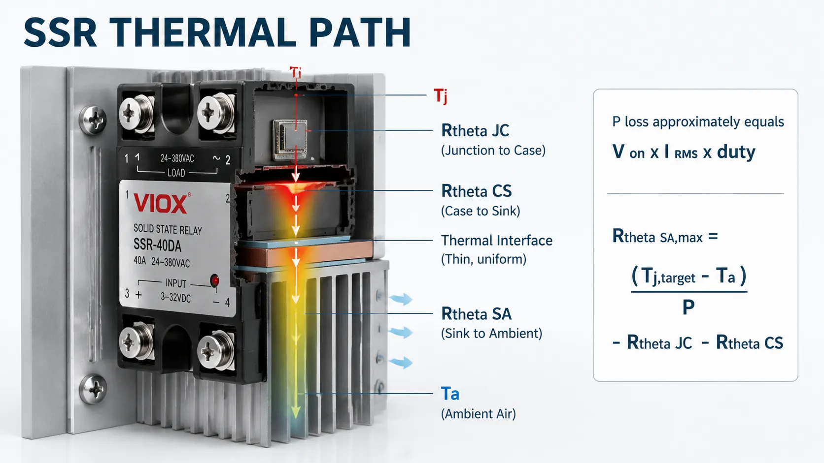
ການສູນເສຍການນຳໄຟຟ້າຂອງ AC SSR
ສຳລັບການປະເມີນເບື້ອງຕົ້ນໂດຍໃຊ້ແຮງດັນຕົກໃນສະພາວະເປີດ:
ສູດການສູນເສຍການນຳໄຟຟ້າຂອງ AC SSR
Ppole ≈ VON × IRMS × D
ບ່ອນທີ່:
- VON: ແຮງດັນຕົກຄ່ອມໃນສະພາວະເປີດ
- IRMS: ກະແສໄຟຟ້າ RMS
- D: ອັດຕາສ່ວນໜ້າທີ່ (Duty ratio)
ໂດຍທີ່ D ແມ່ນອັດຕາສ່ວນໜ້າທີ່ໃນການເຮັດວຽກ. ຖ້າຜູ້ຜະລິດມີເສັ້ນສະແດງການສູນເສຍພະລັງງານໃຫ້, ໃຫ້ໃຊ້ເສັ້ນສະແດງນັ້ນ ເນື່ອງຈາກແຮງດັນຕົກຄ່ອມບໍ່ໄດ້ຄົງທີ່ຢ່າງສົມບູນ.
ການສູນເສຍການນຳໄຟຟ້າຂອງ DC MOSFET SSR
ສຳລັບຜົນຜະລິດ MOSFET:
ສູດການສູນເສຍພະລັງງານຂອງ DC MOSFET SSR
Ppole ≈ IRMS² × RDS(on) × D
ບ່ອນທີ່:
- RDS(on): ຄວາມຕ້ານທານໃນສະພາະເປີດຂອງ MOSFET
- D: ອັດຕາສ່ວນໜ້າທີ່ (Duty ratio)
ໃຫ້ໃຊ້ຄ່າ R_{DS(on)} ທີ່ອຸນຫະພູມຈຸດຕໍ່ເຊື່ອມ (junction temperature) ທີ່ຄາດໄວ້ ບໍ່ແມ່ນພຽງແຕ່ຄ່າທີ່ລະບຸໄວ້ໃນອຸນຫະພູມຕ່ຳເທົ່ານັ້ນ. ໂດຍທົ່ວໄປແລ້ວ ຄວາມຕ້ານທານຂອງ MOSFET ຈະເພີ່ມຂຶ້ນຕາມອຸນຫະພູມ.
ຄວາມຕ້ານທານຄວາມຮ້ອນຂອງແຜ່ນລະບາຍຄວາມຮ້ອນ
ສຳລັບ SSR ໜຶ່ງຕົວເທິງແຜ່ນລະບາຍຄວາມຮ້ອນໜຶ່ງແຜ່ນ:
ສູດຄວາມຕ້ານທານຄວາມຮ້ອນຂອງແຜ່ນລະບາຍຄວາມຮ້ອນ
RθSA,max = (TJ,target − TA) ÷ P − RθJC − RθCS
ບ່ອນທີ່:
- TJ,target: ອຸນຫະພູມຈຸດຕໍ່ເປົ້າໝາຍ
- TA: ອຸນຫະພູມສະພາບແວດລ້ອມ
- P: ການສູນເສຍພະລັງງານຂອງ SSR
ບ່ອນທີ່:
- T_{J,target} ແມ່ນຂີດຈຳກັດອຸນຫະພູມຈຸດຕໍ່ໃນການອອກແບບ, ເຊິ່ງຮັກສາໄວ້ໃຫ້ຕ່ຳກວ່າຄ່າສູງສຸດຢ່າງເດັດຂາດ;
- T_A ແມ່ນອຸນຫະພູມອາກາດທ້ອງຖິ່ນອ້ອມຮອບຮີດຊິງ (heat sink);
- P ແມ່ນການສູນເສຍພະລັງງານຂອງ SSR;
- R_{\theta JC} ແມ່ນຄວາມຕ້ານທານຄວາມຮ້ອນຈາກຈຸດຕໍ່ຫາຕົວເຄື່ອງ;
- R_{\theta CS} ແມ່ນຄວາມຕ້ານທານຄວາມຮ້ອນຈາກຕົວເຄື່ອງຫາຮີດຊິງ;
- R_{\theta SA} ແມ່ນຄວາມຕ້ານທານຄວາມຮ້ອນຈາກແຜ່ນລະບາຍຄວາມຮ້ອນສູ່ສະພາບແວດລ້ອມທີ່ຕ້ອງການ ມີຫົວໜ່ວຍເປັນອົງສາເຊນຊຽດຕໍ່ວັດ.
R_{\theta SA} ທີ່ຕໍ່າກວ່າໝາຍເຖິງແຜ່ນລະບາຍຄວາມຮ້ອນທີ່ມີປະສິດທິພາບຫຼາຍກວ່າ.
ຕົວຢ່າງການຄິດໄລ່
ສົມມຸດວ່າ AC SSR ຕົວໜຶ່ງນຳກະແສໄຟຟ້າ 18 A ຢ່າງຕໍ່ເນື່ອງ, ມີແຮງດັນຕົກຄ່ອມຂະນະເຮັດວຽກ 1.6 V ແລະ ຖືກຕິດຕັ້ງໃນບ່ອນທີ່ອຸນຫະພູມສະພາບແວດລ້ອມອາດສູງເຖິງ 45 ອົງສາ C.
P = 1.6 \times 18 = 28.8\ W
ຖ້າການອອກແບບກຳນົດອຸນຫະພູມຈຸດຕໍ່ (junction temperature) ໄວ້ທີ່ 100 ອົງສາ C, R_{\theta JC}=0.5 ອົງສາ C/W ແລະ R_{\theta CS}=0.2 ອົງສາ C/W:
R_{\theta SA,max} = ÷{100-45}{28.8} – 0.5 – 0.2 \approx 1.21\ ^\circ C/W
ແຜ່ນລະບາຍຄວາມຮ້ອນທີ່ເລືອກຕ້ອງສາມາດສະໜອງໄດ້ 1.21 ອົງສາ C/W ຫຼື ຕ່ຳກວ່າ ພາຍໃຕ້ທິດທາງການຕິດຕັ້ງຕົວຈິງ, ການໄຫຼວຽນຂອງອາກາດໃນຕູ້, ລະດັບຄວາມສູງ, ແລະ ເງື່ອນໄຂການຕິດຕັ້ງ. ຕົວຢ່າງນີ້ແມ່ນເພື່ອໃຫ້ເຫັນພາບ; ໃຫ້ໃຊ້ຂໍ້ມູນການສູນເສຍພະລັງງານຂອງ SSR ແລະ ຄ່າຄວາມຕ້ານທານຄວາມຮ້ອນທີ່ແນ່ນອນ.
SSR ຫຼາຍຕົວເທິງແຜ່ນລະບາຍຄວາມຮ້ອນດຽວກັນ
ເມື່ອໂມດູນຫຼາຍຕົວໃຊ້ແຜ່ນລະບາຍຄວາມຮ້ອນຮ່ວມກັນ, ຄວາມຮ້ອນລວມຈະເຮັດໃຫ້ອຸນຫະພູມຂອງແຜ່ນລະບາຍຄວາມຮ້ອນສູງຂຶ້ນ ໃນຂະນະທີ່ແຕ່ລະໂມດູນຍັງຄົງຮັກສາເສັ້ນທາງການຖ່າຍເທຄວາມຮ້ອນຈາກຈຸດເຊື່ອມຕໍ່ໄປຫາຕົວເຄື່ອງ (junction-to-case) ຂອງຕົນເອງ:
ສູດຄິດໄລ່ອຸນຫະພູມຈຸດເຊື່ອມຕໍ່ຂອງ SSR
TJ = TA + Ptotal × RθSA + Pmodule × (RθJC + RθCS)
ບ່ອນທີ່:
- TJ: ອຸນຫະພູມຈຸດເຊື່ອມຕໍ່
- TA: ອຸນຫະພູມສະພາບແວດລ້ອມ
ຢ່າຄິດໄລ່ SSR ແຕ່ລະຕົວໂດຍສົມມຸດວ່າແຕ່ລະຕົວມີແຜ່ນລະບາຍຄວາມຮ້ອນເປັນຂອງຕົນເອງທັງໝົດ.
10. ພິຈາລະນາອຸນຫະພູມຂອງຕູ້ຄວບຄຸມ, ການຈັດກຸ່ມ, ແລະ ການຕິດຕັ້ງ
ອຸນຫະພູມຫ້ອງບໍ່ແມ່ນອຸນຫະພູມສະພາບແວດລ້ອມທີ່ໃຊ້ໃນການອອກແບບ. ໃຫ້ວັດແທກ ຫຼື ຄາດຄະເນອຸນຫະພູມອາກາດໃກ້ກັບ SSR ແລະ ຊ່ອງທາງເຂົ້າຂອງແຜ່ນລະບາຍຄວາມຮ້ອນ ຫຼັງຈາກທີ່ຕູ້ຄວບຄຸມບັນລຸສະພາວະສົມດຸນທາງຄວາມຮ້ອນແລ້ວ.
ສາເຫດທົ່ວໄປຂອງການປະເມີນອຸນຫະພູມ SSR ຕໍ່າເກີນໄປປະກອບມີ:
- ຕູ້ຄວບຄຸມແບບປິດທີ່ຖືກແສງແດດ;
- ແຜ່ນລະບາຍຄວາມຮ້ອນທີ່ຕິດຕັ້ງໃນບ່ອນທີ່ການລະບາຍອາກາດຕາມທຳມະຊາດຖືກກີດຂວາງ;
- ການຈັດກຸ່ມ SSR, ຄອນແທັກເຕີ, ຫຼື ແຫຼ່ງຈ່າຍໄຟຫຼາຍອັນໄວ້ໃກ້ກັນ;
- ຄີບລະບາຍຄວາມຮ້ອນແນວນອນທີ່ບໍ່ສາມາດສ້າງເສັ້ນທາງການໄຫຼວຽນຂອງອາກາດຂຶ້ນສູ່ດ້ານເທິງໄດ້;
- ລະດັບຄວາມສູງ, ຕົວກອງຝຸ່ນ, ຫຼື ປະສິດທິພາບຂອງລະບົບລະບາຍອາກາດແບບບັງຄັບທີ່ຫຼຸດລົງ;
- ສານລະບາຍຄວາມຮ້ອນຫຼາຍເກີນໄປ ຫຼື ໃຊ້ບໍ່ຖືກວິທີ;
- ແຮງກົດໃນການຕິດຕັ້ງບໍ່ສະໝ່ຳສະເໝີ ຫຼື ພື້ນຜິວຂອງແຜ່ນລະບາຍຄວາມຮ້ອນບິດເບี้ยว.
ໃຫ້ປະຕິບັດຕາມຄຳແນະນຳຂອງຜູ້ຜະລິດ SSR ກ່ຽວກັບແຮງບິດ, ຄວາມຮາບພຽງ, ແຜ່ນລະບາຍຄວາມຮ້ອນ ແລະ ການຕິດຕັ້ງ. ການໃຊ້ສານລະບາຍຄວາມຮ້ອນຫຼາຍເກີນໄປບໍ່ໄດ້ສົ່ງຜົນດີ; ວັດສະດຸເຊື່ອມຕໍ່ຄວນຕື່ມເຕັມຊ່ອງຫວ່າງຂະໜາດນ້ອຍໂດຍບໍ່ສ້າງເປັນຊັ້ນສນວນທີ່ໜາເກີນໄປ.
ແຜ່ນລະບາຍຄວາມຮ້ອນແບບລວມສູນ ຫຼື ແຜ່ນລະບາຍຄວາມຮ້ອນແບບແຍກຕ່າງຫາກ?
SSR ທີ່ມີແຜ່ນລະບາຍຄວາມຮ້ອນແບບ DIN-rail ໃນຕົວສາມາດຫຼຸດຈຳນວນຊິ້ນສ່ວນ ແລະ ເວລາໃນການປະກອບໄດ້, ໃນຂະນະທີ່ແຜ່ນລະບາຍຄວາມຮ້ອນແບບແຍກຕ່າງຫາກຈະຊ່ວຍໃຫ້ຜູ້ອອກແບບມີອິດສະຫຼະຫຼາຍຂຶ້ນໃນການຈັດການກັບການສູນເສຍພະລັງງານທີ່ຫຼາຍກວ່າ, ການແບ່ງປັນໂຫຼດຄວາມຮ້ອນ, ການໄຫຼວຽນຂອງອາກາດ ແລະ ການປ່ຽນແທນ. ບໍ່ມີໂຄງສ້າງໃດທີ່ດີກວ່າກັນໂດຍທຳມະຊາດ.
| ການຕັ້ງຄ່າ | ຂໍ້ໄດ້ປຽບຕົ້ນຕໍ | ຂໍ້ຈໍາກັດຕົ້ນຕໍ | ວິທີການປະເມີນຜົນທີ່ດີທີ່ສຸດ |
|---|---|---|---|
| ແຜ່ນລະບາຍຄວາມຮ້ອນແບບລວມສູນ | ການປະກອບທີ່ກະທັດຮັດ ແລະ ການຕິດຕັ້ງທີ່ງ່າຍດາຍ | ຄວາມສາມາດໃນການລະບາຍຄວາມຮ້ອນທີ່ຄົງທີ່ ແລະ ຄວາມເປັນໄປໄດ້ທີ່ຈະມີຄວາມແອອັດພາຍໃນເຂດລາງ DIN | ກວດສອບກະແສໄຟຟ້າທີ່ອະນຸຍາດໃຫ້ໃຊ້ໄດ້ທີ່ອຸນຫະພູມອ້ອມຂ້າງຂອງຕູ້ໄຟຟ້າຕົວຈິງ ແລະ ໄລຍະຫ່າງ |
| ແຜ່ນລະບາຍຄວາມຮ້ອນແບບແຍກ | ມີທາງເລືອກທີ່ກວ້າງຂວາງກວ່າໃນດ້ານຄວາມຕ້ານທານຄວາມຮ້ອນ, ຂະໜາດ ແລະ ການໄຫຼວຽນຂອງອາກາດ | ຕ້ອງໃຊ້ວຽກງານໃນການຕິດຕັ້ງຫຼາຍຂຶ້ນ ແລະ ມີຄວາມຂຶ້ນກັບຄຸນນະພາບຂອງຈຸດເຊື່ອມຕໍ່ຫຼາຍກວ່າ | ຄຳນວນເສັ້ນທາງຄວາມຮ້ອນທັງໝົດ ແລະ ກວດສອບອຸນຫະພູມຂອງຕົວເຄື່ອງ |
| ແຜ່ນລະບາຍຄວາມຮ້ອນແບບໃຊ້ຮ່ວມກັນ | ສາມາດຫຼຸດຜ່ອນພື້ນທີ່ໃນຕູ້ໄຟຟ້າສຳລັບ SSR ຫຼາຍຕົວ | ຄວາມຮ້ອນຈາກທຸກໂມດູນຈະເຮັດໃຫ້ອຸນຫະພູມຂອງແຜ່ນລະບາຍຄວາມຮ້ອນລວມສູງຂຶ້ນ | ໃຫ້ໃຊ້ຄ່າການສູນເສຍຄວາມຮ້ອນລວມບວກກັບເສັ້ນທາງການເຊື່ອມຕໍ່ຂອງແຕ່ລະໂມດູນ |
ຢ່າເລືອກລະຫວ່າງທາງເລືອກເຫຼົ່ານີ້ໂດຍພິຈາລະນາຈາກກະແສໂຫຼດພຽງຢ່າງດຽວ. ໃຫ້ປຽບທຽບຂອບເຂດອຸນຫະພູມຈຸດຕໍ່ທີ່ໄດ້ຮັບພາຍໃຕ້ເງື່ອນໄຂຂອງຕູ້ຄວບຄຸມດຽວກັນ.
11. ເຂົ້າໃຈກ່ຽວກັບກະແສຮົ່ວໄຫຼໃນສະພາວະປິດ (Off-State Leakage) ແລະ ໂຫຼດຂັ້ນຕໍ່າ
SSR ບໍ່ໄດ້ເຮັດວຽກຄືກັບຊ່ອງວ່າງອາກາດທາງກົນ. ເຊມິຄອນດັກເຕີຂາອອກຂອງມັນ ແລະ ວົງຈອນສະນັບເບີ (snubber) ພາຍໃນຈະຍອມໃຫ້ກະແສໄຟຟ້າຈຳນວນໜ້ອຍໜຶ່ງໄຫຼຜ່ານໃນຂະນະທີ່ປິດຢູ່.
ການຮົ່ວໄຫຼນີ້ສາມາດເຮັດໃຫ້ເກີດ:
- ຫຼອດໄຟ LED ເກີດແສງສະຫວ່າງ ຫຼື ກະພິບ;
- ມິເຕີທີ່ມີຄວາມຕ້ານທານສູງສະແດງຄ່າແຮງດັນໄຟຟ້າຫຼອກ (ghost voltage);
- ໂຊລີນອຍຂະໜາດນ້ອຍເກີດສຽງດັງ ຫຼື ບໍ່ສາມາດປ່ອຍໄດ້;
- ແຫຼ່ງຈ່າຍໄຟເອເລັກໂຕຣນິກສາກໄຟ ແລະ ເລີ່ມຕົ້ນການເຮັດວຽກໃໝ່ເປັນໄລຍະ;
- ໂຫຼດປະກົດວ່າຢູ່ໃນສະຖານະມີໄຟໃນລະຫວ່າງການແກ້ໄຂບັນຫາ.
ປຽບທຽບກະແສຮົ່ວໄຫຼໃນສະຖານະປິດ (off-state leakage) ສູງສຸດຂອງ SSR ກັບກະແສການປ່ອຍ (release current) ແລະ ກະແສການເຮັດວຽກຂັ້ນຕ່ຳຂອງໂຫຼດ. ຕົວຕ້ານທານແບບ bleed resistor ທີ່ໄດ້ຮັບການອະນຸມັດຈາກຜູ້ຜະລິດອາດຈະແກ້ໄຂບັນຫາໂຫຼດຂະໜາດນ້ອຍບາງຢ່າງໄດ້ ແຕ່ມັນຈະເພີ່ມຄວາມຮ້ອນ ແລະ ຕ້ອງມີພິກັດແຮງດັນທີ່ເໝາະສົມສຳລັບການໃຊ້ງານຢ່າງຕໍ່ເນື່ອງ ແລະ ການຄາຍປະຈຸທີ່ປອດໄພ. ວົງຈອນ RC snubber ພາຍນອກຍັງສາມາດເພີ່ມກະແສຮົ່ວໄຫຼໄດ້ອີກດ້ວຍ.
ຕ້ອງຕັດແຍກວົງຈອນ ແລະ ກວດສອບໃຫ້ແນ່ໃຈວ່າບໍ່ມີແຮງດັນໄຟຟ້າກ່ອນການບຳລຸງຮັກສາສະເໝີ. ຄຳສັ່ງປິດ (off command) ຂອງ SSR ບໍ່ແມ່ນວິທີການຕັດແຍກວົງຈອນທີ່ປອດໄພ.
12. ການປະສານງານການປ້ອງກັນອ້ອມຮອບ SSR
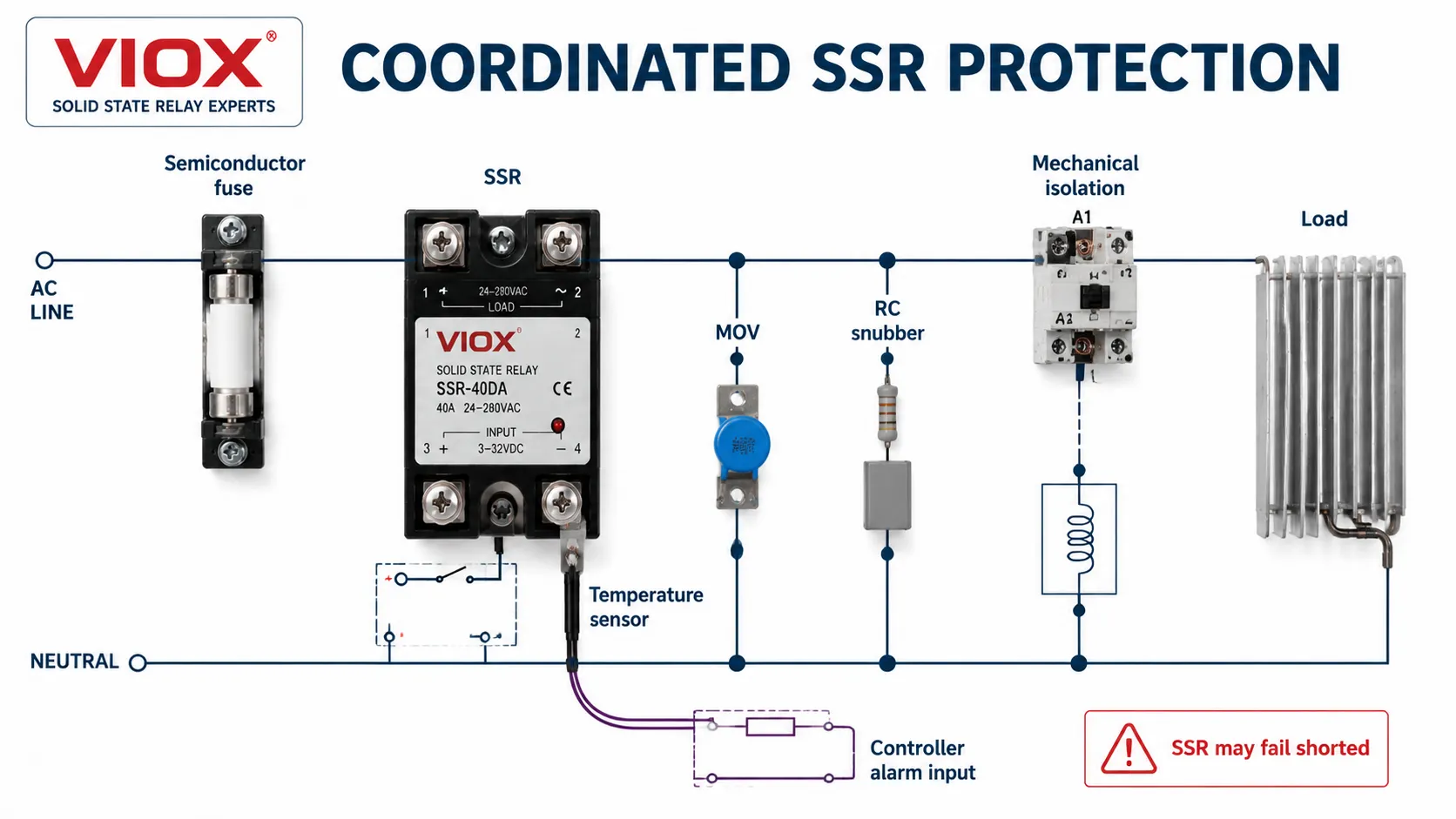
ບໍ່ມີອຸປະກອນປ້ອງກັນພຽງອັນດຽວທີ່ສາມາດປ້ອງກັນຄວາມຄຽດທຸກຢ່າງຂອງ SSR ໄດ້.
| ມາດຕະການປ້ອງກັນ | ຈຸດປະສົງຫຼັກ | ຂໍ້ຄວນລະວັງໃນການເລືອກໃຊ້ |
|---|---|---|
| ເບຣກເກີວົງຈອນຍ່ອຍ ຫຼື ຟິວລວມ | ການປ້ອງກັນສາຍໄຟ ແລະ ວົງຈອນ | ອາດຈະຊ້າເກີນໄປທີ່ຈະປ້ອງກັນຈຸດເຊື່ອມຕໍ່ສານກຶ່ງຕົວນຳ |
| ຟິວສຳລັບສານກຶ່ງຕົວນຳແບບໄວ | ຈຳກັດພະລັງງານຄວາມຜິດພາດຜ່ານ SSR | ໃຊ້ຕາຕະລາງການປະສານງານຂອງຜູ້ຜະລິດ SSR ຫຼື ປຽບທຽບຕາມພື້ນຖານການທົດສອບທົ່ວໄປທີ່ຖືກຕ້ອງ |
| MOV | ຈຳກັດແຮງດັນເກີນທີ່ເກີດຂຶ້ນຊ້ຳໆ ຫຼື ເປັນຄັ້ງຄາວ | ປະສານງານ MCOV, ລະດັບການໜີບ (clamping level), ພະລັງງານ, ການເສື່ອມສະພາບ ແລະ ກະແສໄຟຟ້າຕາມ (follow current) |
| RC snubber | ຈຳກັດ dv/dt ແລະ ການສັ່ນສະເທືອນ (ringing) ໃນວົງຈອນອິນດັກທີຟ AC | ເພີ່ມການຮົ່ວໄຫຼໃນສະຖານະປິດ (off-state leakage) ແລະ ຄວາມຮ້ອນ |
| Flyback diode | ສະກັດກັ້ນແຮງດັນກະຊາກ (inductive kick) ຂອງຄອຍ DC | ເຮັດໃຫ້ການປ່ອຍຄອຍຊ້າລົງ ແລະ ຕ້ອງມີຂົ້ວທີ່ຖືກຕ້ອງ |
| ໄດໂອດ TVS | ໜີບແຮງດັນຊົ່ວຄາວ DC ໄວ້ທີ່ແຮງດັນສູງກວ່າ | ການປ່ອຍໂຫຼດໄວຂຶ້ນ ແຕ່ມີຄວາມຄຽດສູງກວ່າໄດໂອດຟລາຍແບັກ (flyback diode) |
| ສະວິດຄວາມຮ້ອນ ຫຼື ເຊັນເຊີ | ກວດຈັບອຸນຫະພູມເກີນຂອງແຜ່ນລະບາຍຄວາມຮ້ອນ | ຕິດຕັ້ງໄວ້ໃນຈຸດທີ່ເປັນຕົວແທນຂອງເສັ້ນທາງຄວາມຮ້ອນທີ່ສຳຄັນ |
| ຄອນແທັກເຕີ/ອຸປະກອນຕັດວົງຈອນແບບກົນຈັກ | ສະໜອງການແຍກວົງຈອນ ຫຼື ການປິດລະບົບສຳຮອງ | ຕ້ອງມີການປະສານງານກັນສຳລັບການຈັດລຳດັບ ແລະ ການຮັບມືກັບຄວາມຜິດພາດ |
ການປະສານງານຟິວສຳລັບອຸປະກອນກึ่งຕົວນຳ
MCCB ຫຼື MCB ສາມາດຕັດວົງຈອນເມື່ອເກີດຄວາມຜິດພາດໄດ້ ແຕ່ຍັງອາດປ່ອຍໃຫ້ພະລັງງານໄຫຼຜ່ານຫຼາຍພໍທີ່ຈະເຮັດໃຫ້ SSR ເສຍຫາຍ. ໃນກໍລະນີທີ່ຕ້ອງການການປ້ອງກັນອຸປະກອນກึ่งຕົວນຳ ໃຫ້ໃຊ້ຟິວຄວາມໄວສູງທີ່ຜູ້ຜະລິດ SSR ແນະນຳ.
ການປຽບທຽບພະລັງງານກໍາມະຈອນເບື້ອງຕົ້ນອາດໃຊ້:
ການປະເມີນພະລັງງານຂອງກຳມະຈອນ
I²t ≈ Ipeak² × tpulse
ບ່ອນທີ່:
- Ipeak: ກະແສໄຟຟ້າສູງສຸດ
- tpulse: ໄລຍະເວລາຂອງກຳມະຈອນ
ຢ່າງໃດກໍຕາມ, ຄ່າ I^2t ໃນການຕັດວົງຈອນທັງໝົດຂອງຟິວ ແລະ ຄ່າ I^2t ທີ່ SSR ສາມາດທົນໄດ້ນັ້ນ ຈະມີຄວາມໝາຍກໍຕໍ່ເມື່ອຮູບຄື້ນ, ໄລຍະເວລາ, ອຸນຫະພູມເລີ່ມຕົ້ນ, ແຮງດັນໄຟຟ້າຂອງລະບົບ ແລະ ເງື່ອນໄຂການທົດສອບມີຄວາມສອດຄ່ອງກັນ. ຕາຕະລາງການປະສານງານທີ່ໄດ້ຮັບການອະນຸມັດຖືເປັນຫຼັກຖານທີ່ໜ້າເຊື່ອຖືໄດ້ຫຼາຍກວ່າການປຽບທຽບໝາຍເລກລາຍການສິນຄ້າແບບແຍກສ່ວນ.
ການເລືອກ MOV ແລະ ສະນັບເບີ (snubber)
ແຮງດັນໄຟຟ້າປະຕິບັດງານຕໍ່ເນື່ອງສູງສຸດຂອງ MOV ຕ້ອງສູງກວ່າແຮງດັນໄຟຟ້າໃນສາຍປົກກະຕິທີ່ສູງທີ່ສຸດ, ໃນຂະນະທີ່ລະດັບການປ້ອງກັນຂອງມັນຄວນຈະຕໍ່າກວ່າຄ່າການທົນຕໍ່ແຮງດັນຊົ່ວຄາວທີ່ກ່ຽວຂ້ອງຂອງ SSR. ການເກີດແຮງດັນຊົ່ວຄາວຊໍ້າໆ, ຄ່າອິມພີແດນສ໌ຂອງແຫຼ່ງຈ່າຍ ແລະ ພຶດຕິກຳເມື່ອໝົດອາຍຸການໃຊ້ງານຂອງ MOV ກໍມີຄວາມສຳຄັນເຊັ່ນກັນ.
RC ສະນັບເບີ (RC snubber) ມີປະໂຫຍດໃນກໍລະນີທີ່ຄ່າ dv/dt ຫຼາຍເກີນໄປ ຫຼື ການເກີດສັນຍານລົບກວນຈາກອິນດັກທີຟ (inductive ringing) ເປັນໄພຄຸກຄາມທີ່ເຮັດໃຫ້ເກີດການເປີດວົງຈອນຜິດພາດ ຫຼື ເຮັດໃຫ້ອຸປະກອນເກີດຄວາມຄຽດ. ມັນຄວນຈະຖືກອອກແບບໃຫ້ເປັນສ່ວນໜຶ່ງຂອງວົງຈອນ ບໍ່ແມ່ນການເພີ່ມເຂົ້າໄປໂດຍອັດຕະໂນມັດ ເພາະມັນຈະເຮັດໃຫ້ກະແສໄຟຟ້າໃນສະພາວະປິດ (off-state current) ເພີ່ມຂຶ້ນ.
ໃຫ້ໃຊ້ທ່າອ່ຽງຂອງອຸນຫະພູມ ບໍ່ແມ່ນພຽງແຕ່ຈຸດຕັດການເຮັດວຽກທີ່ກຳນົດໄວ້ເທົ່ານັ້ນ
ໃນອຸປະກອນທີ່ເຮັດວຽກຢ່າງຕໍ່ເນື່ອງ ຫຼື ມີຄວາມສຳຄັນສູງ ເຊັນເຊີອຸນຫະພູມທີ່ແຜ່ນລະບາຍຄວາມຮ້ອນສາມາດໃຫ້ຜົນໄດ້ຫຼາຍກວ່າການປິດເຄື່ອງສຸກເສີນ. ການຕິດຕາມທ່າອ່ຽງຂອງອຸນຫະພູມຮ່ວມກັບກະແສໂຫຼດ ແລະ ອຸນຫະພູມອ້ອມຂ້າງຕູ້ຄວບຄຸມ ສາມາດເປີດເຜີຍໃຫ້ເຫັນທາງລົມທີ່ອຸດຕັນ, ພັດລົມເສຍ, ແຜ່ນລະບາຍຄວາມຮ້ອນເປື້ອນ, ການເຊື່ອມຕໍ່ຄວາມຮ້ອນທີ່ຫຼວມ ຫຼື ຮອບວຽນການເຮັດວຽກທີ່ເພີ່ມຂຶ້ນ ກ່ອນທີ່ SSR ຈະຮອດຈຸດຕັດການເຮັດວຽກ.
ອຸນຫະພູມແຜ່ນລະບາຍຄວາມຮ້ອນທີ່ສູງຂຶ້ນບໍ່ໄດ້ເປັນຫຼັກຖານວ່າ SSR ເອງມີຂໍ້ບົກພ່ອງ. ໃຫ້ປຽບທຽບຄ່າທີ່ອ່ານໄດ້ໃນສະພາບໂຫຼດ ແລະ ສະພາບແວດລ້ອມທີ່ຄ້າຍຄືກັນ ແລະ ກວດສອບເສັ້ນທາງການລະບາຍຄວາມຮ້ອນທັງໝົດ. ສະວິດຄວາມຮ້ອນທີ່ເຊື່ອມຕໍ່ກັບອິນພຸດຄວບຄຸມພຽງຢ່າງດຽວ ບໍ່ສາມາດຕັດໂຫຼດໄດ້ຫຼັງຈາກທີ່ SSR ເກີດການລັດວົງຈອນພາຍໃນ; ຈຳເປັນຕ້ອງມີອຸປະກອນສະວິດກົນຈັກ ຫຼື ອຸປະກອນແຍກວົງຈອນຕ່າງຫາກ ໃນກໍລະນີທີ່ການປະເມີນຄວາມສ່ຽງຮຽກຮ້ອງໃຫ້ມີການຕັດວົງຈອນຢ່າງເດັດຂາດ.
13. ການອອກແບບສຳລັບຮູບແບບການເສຍຂອງ SSR ທີ່ພົບເລື້ອຍ
ອຸປະກອນກึ่งຕົວນຳກຳລັງມັກຈະເສຍໃນລັກສະນະ ລັດວົງຈອນ, ໂດຍສະເພາະຫຼັງຈາກເກີດອຸນຫະພູມສູງເກີນ, ກະແສກະຊາກ, ແຮງດັນເກີນ ຫຼື ການຈຳກັດພະລັງງານຄວາມຜິດພາດທີ່ບໍ່ພຽງພໍ. ໂຫຼດອາດຈະຍັງມີໄຟລ້ຽງຢູ່ເຖິງແມ່ນວ່າອິນພຸດຄວບຄຸມຈະປິດຢູ່ກໍຕາມ.
| ອາການ | ສາເຫດທີ່ເປັນໄປໄດ້ | ການຕອບສະໜອງທາງວິສະວະກຳ |
|---|---|---|
| ໂຫຼດຍັງຄົງເຮັດວຽກເຕັມທີ່ | ເຊມິຄອນດັກເຕີຜົນຜະລິດເສຍຫາຍໃນສະພາວະວົງຈອນສັ້ນ; ມີການຕໍ່ສາຍບາຍພາດ | ຕັດແຫຼ່ງຈ່າຍໄຟ, ກວດສອບຄວາມຕ້ານທານຜົນຜະລິດໂດຍອີງຕາມວິທີການທົດສອບຂອງຜູ້ຜະລິດ, ປ່ຽນ SSR, ແລະ ສືບສວນຫາສາເຫດດ້ານຄວາມຮ້ອນ ແລະ ແຮງດັນເກີນ |
| ໂຫຼດບໍ່ເຮັດວຽກ | ຜົນຜະລິດເປີດວົງຈອນ, ການຂັບອິນພຸດບໍ່ພຽງພໍ, ຟິວຂາດ, ໂຫຼດມີບັນຫາ | ວັດແທກອິນພຸດຄວບຄຸມ, ແຮງດັນຜົນຜະລິດ, ຄວາມຕໍ່ເນື່ອງຂອງຟິວ, ແລະ ກະແສໂຫຼດຢ່າງປອດໄພ |
| ເຮັດວຽກໄດ້ໃນສະພາວະເຢັນ, ເສຍຫາຍໃນສະພາວະຮ້ອນ | ແຜ່ນລະບາຍຄວາມຮ້ອນບໍ່ພຽງພໍ, ການເຊື່ອມຕໍ່ບໍ່ດີ, ອຸນຫະພູມສະພາບແວດລ້ອມສູງເກີນໄປ, ອິນພຸດຢູ່ໃນລະດັບໝິ່ມເໝ່ | ບັນທຶກອຸນຫະພູມຂອງກໍລະນີ/ຮີດຊິງ ແລະ ກະແສໄຟຟ້າຫຼັງຈາກຄວາມຮ້ອນຄົງທີ່ |
| ຟິວເຮັດວຽກຜິດປົກກະຕິ | ການປະເມີນກະແສໄຟຟ້າກະຊາກ (inrush) ຕໍ່າເກີນໄປ, ໃຊ້ຟິວຜິດ, ມີກະແສໄຟຟ້າກະຊາກຊໍ້າໆ | ບັນທຶກຮູບຄື້ນຂອງກະແສໄຟຟ້າກະຊາກ (inrush) ແລະ ກວດສອບການປະສານງານລະຫວ່າງຟິວ/SSR |
| ການເປີດເຮັດວຽກທີ່ຜິດພາດ | ຄ່າ dv/dt ສູງເກີນໄປ, ສັນຍານລົບກວນໃນການຄວບຄຸມ, ການເຊື່ອມຕໍ່ສາຍໄຟ | ປັບປຸງການເດີນສາຍໄຟ, ການປ້ອງກັນສັນຍານລົບກວນ, ການປ້ອງກັນສັນຍານລົບກວນຈາກພາຍນອກ ແລະ ຂອບເຂດສັນຍານລົບກວນຂາເຂົ້າ |
| ໂຫຼດຂະໜາດນ້ອຍມີແສງສະຫວ່າງ ຫຼື ສັ່ນໃນຂະນະທີ່ປິດຢູ່ | ກະແສໄຟຟ້າຮົ່ວ ຫຼື ກະແສໄຟຟ້າສະນັບເບີ (snubber current) | ກວດສອບກະແສໄຟຟ້າຮົ່ວສູງສຸດທຽບກັບຄຸນລັກສະນະການປ່ອຍໂຫຼດ; ໃຫ້ໃຊ້ເຄືອຂ່າຍລະບາຍກະແສ (bleed network) ທີ່ໄດ້ຮັບການອະນຸມັດ ຫຼື ສະຖາປັດຕະຍະກຳຜົນຜະລິດອື່ນ |
ໃນກໍລະນີທີ່ການຈ່າຍໄຟຕໍ່ເນື່ອງອາດເຮັດໃຫ້ເກີດອັກຄີໄພ, ການເຄື່ອນໄຫວ, ແຮງດັນ, ຫຼື ອັນຕະລາຍຈາກຂະບວນການເຮັດວຽກ, ຢ່າເພິ່ງພາ SSR ພຽງຕົວດຽວເພື່ອຄວາມປອດໄພ. ໃຫ້ໃຊ້ຕົວຕັດວົງຈອນທາງກົນທີ່ເໝາະສົມ ຫຼື ສະຖາປັດຕະຍະກຳທີ່ໄດ້ມາດຕະຖານຄວາມປອດໄພ, ການປ້ອງກັນອຸນຫະພູມເກີນທີ່ເປັນອິດສະຫຼະ, ແລະ ການຕິດຕາມຄວາມຜິດພາດຕາມທີ່ການປະເມີນຄວາມສ່ຽງກຳນົດໄວ້.
14. ຂໍ້ກຳນົດການຈັດຊື້ SSR
ລາຍລະອຽດການຈັດຊື້ເຊັ່ນ “40 A SSR, 24 V input” ແມ່ນບໍ່ຄົບຖ້ວນ. ໃຫ້ໃຊ້ຂໍ້ກຳນົດທີ່ຊ່ວຍໃຫ້ຜູ້ສະໜອງ ແລະ ຜູ້ປະກອບຕູ້ຄວບຄຸມສາມາດປະເມີນການນຳໃຊ້ຕົວຈິງໄດ້.
| ຊ່ອງຂໍ້ມູນສະເປັກ | ຂໍ້ມູນທີ່ຕ້ອງຮ້ອງຂໍ ຫຼື ຈັດຫາໃຫ້ |
|---|---|
| ຄໍາຮ້ອງສະຫມັກ | ອຸປະກອນໂຫຼດ, ຈຸດປະສົງໃນການສະຫຼັບ, ຮອບວຽນການເຮັດວຽກ (duty cycle), ຈຳນວນຄັ້ງທີ່ເລີ່ມຕົ້ນ/ຮອບວຽນຕໍ່ຊົ່ວໂມງ |
| ການປ້ອນຂໍ້ມູນ | ຄ່າລະບຸ/ຊ່ວງ, ກະແສໄຟຟ້າຂາເຂົ້າ, ລະດັບການເຮັດວຽກ (pickup/dropout), ຂົ້ວໄຟຟ້າ, ປະເພດຜົນຜະລິດຂອງ PLC |
| ເຕັກໂນໂລຊີຜົນຜະລິດ | AC triac/SCR, DC MOSFET, DC ແບບສອງທິດທາງ, ຫຼື ແບບສາມເຟສລວມ |
| ການສະໜອງໂຫຼດ | ແຮງດັນໄຟຟ້າລະບຸ ແລະ ສູງສຸດ, ຄວາມຖີ່, ການຈັດລຽງເຟສ |
| ຂໍ້ມູນໂຫຼດ | ກະແສ RMS, ຕົວປະກອບກຳລັງ, ປະສິດທິພາບ, ຮູບຄື້ນກະແສກະຊາກ, ໄລຍະເວລາຂອງກະແສກະຊາກ |
| ໂໝດການສະຫຼັບ | ຄວາມເຂົ້າກັນໄດ້ກັບ Zero-cross, random turn-on, ຫຼື ຕົວຄວບຄຸມແບບອັດຕາສ່ວນ |
| ຄວາມສາມາດໃນການຮັບກະແສໄຟຟ້າ | ກະແສໄຟຟ້າຕໍ່ເນື່ອງທີ່ສະພາບແວດລ້ອມ ແລະ ເງື່ອນໄຂການຕິດຕັ້ງທີ່ກຳນົດ |
| ຂໍ້ມູນທາງຄວາມຮ້ອນ | ເສັ້ນສະແດງການສູນເສຍພະລັງງານ, V_{ON} ຫຼື R_{DS(on)}, R_{\theta JC}, ຂໍ້ກຳນົດດ້ານອິນເຕີເຟສ, ເສັ້ນສະແດງການຫຼຸດຄ່າພິກັດ (derating curve) |
| ຂໍ້ມູນສະຖານະປິດ (Off-state) | ກະແສຮົ່ວໄຫຼ, ໂຫຼດຂັ້ນຕໍ່າ, ແຮງດັນປິດກັ້ນ (blocking voltage), ຄ່າ dv/dt ແບບສະຖິດ ແລະ ແບບສະຫຼັບ |
| ຂໍ້ມູນກະແສກະຊາກ (Surge data) | ກະແສສູງສຸດ, ຮູບຮ່າງຄື້ນ, ໄລຍະເວລາຂອງກຳມະຈອນ, ຂີດຈຳກັດການຊໍ້າຄືນ, ພື້ນຖານ I^2t |
| ການປົກປ້ອງ | ຟິວສ໌ສານກິ່ງຕົວນຳທີ່ໄດ້ຮັບການອະນຸມັດ, ຄຳແນະນຳກ່ຽວກັບ MOV/snubber, ທາງເລືອກປ້ອງກັນອຸນຫະພູມເກີນ |
| ກົນຈັກ | ຊຸດອຸປະກອນ (Package), ຂົ້ວຕໍ່, ການຕິດຕັ້ງ, ແຜ່ນລະບາຍຄວາມຮ້ອນ, ແຮງບິດ, ການປ້ອງກັນການສຳຜັດ |
| ເອກະສານ | ການປັບປຸງແຜ່ນຂໍ້ມູນ, ລາຍງານການທົດສອບ, ການຕິດຕາມກວດສອບ, ຫຼັກຖານການຢັ້ງຢືນທີ່ກ່ຽວຂ້ອງ |
15. ລາຍການກວດສອບຜູ້ສະໜອງສຳລັບໂຄງການ OEM ແລະ ຕູ້ຄວບຄຸມ
ກ່ອນທີ່ຈະອະນຸມັດກຸ່ມຜະລິດຕະພັນ SSR, ໃຫ້ຂໍໃຫ້ຜູ້ສະໜອງສະໜອງ:
- ເສັ້ນສະແດງການຫຼຸດຄ່າພິກັດກະແສໄຟຟ້າທຽບກັບອຸນຫະພູມອ້ອມຂ້າງສຳລັບການຕິດຕັ້ງຕົວຈິງ;
- ຂໍ້ມູນການສູນເສຍພະລັງງານຕະຫຼອດຊ່ວງກະແສໄຟຟ້າທີ່ຕ້ອງການ;
- ຄວາມຕ້ານທານຄວາມຮ້ອນຈາກຈຸດເຊື່ອມຕໍ່ຫາຕົວເຄື່ອງ ແລະ ຄຳແນະນຳກ່ຽວກັບພື້ນຜິວສຳຜັດ;
- ເສັ້ນສະແດງກະແສໄຟຟ້າກະຊາກພ້ອມລະບຸຮູບຄື້ນ ແລະ ໄລຍະເວລາ;
- ຮຸ່ນຟິວສ໌ຄວາມໄວສູງທີ່ແນະນຳ ຫຼື ວິທີການປະສານງານທີ່ໄດ້ບັນທຶກໄວ້;
- ກະແສໄຟຟ້າຮົ່ວໄຫຼສູງສຸດ ແລະ ໂຫຼດຕໍ່າສຸດທີ່ອຸນຫະພູມປະຕິບັດງານ;
- ຂໍ້ມູນ dv/dt ແລະ ແຮງດັນໄຟຟ້າຊົ່ວຄາວ;
- ແຮງບິດຂອງຂົ້ວຕໍ່ ແລະ ຂໍ້ກຳນົດຂອງຕົວນຳ;
- ການຕິດຕາມແຫຼ່ງທີ່ມາຂອງລັອດ ແລະ ຂະບວນການຄວບຄຸມການປ່ຽນແປງ;
- ຂໍ້ມູນລັອດການຜະລິດສຳລັບຄຸນລັກສະນະທີ່ສຳຄັນ ເຊັ່ນ: ການຮົ່ວໄຫຼໃນສະພາວະປິດ (off-state leakage), ແຮງດັນຕົກໃນສະພາວະເປີດ (on-state voltage drop), ແຮງດັນການກັ້ນ (blocking voltage), ແລະ ການຮັບສັນຍານຂາເຂົ້າ (input pickup) ບ່ອນທີ່ມີການນຳໃຊ້ການຄວບຄຸມຂະບວນການທາງສະຖິຕິ;
- ຫຼັກຖານສຳລັບການຢັ້ງຢືນ ຫຼື ການປະຕິບັດຕາມມາດຕະຖານໃດໆທີ່ໄດ້ກ່າວອ້າງ;
- ຕົວຢ່າງສຳລັບການກວດສອບການເພີ່ມຂຶ້ນຂອງຄວາມຮ້ອນ, ກະແສໄຟຟ້າກະຊາກ (inrush), ການຮົ່ວໄຫຼ, ແລະ ການຕອບສະໜອງຕໍ່ຄວາມຜິດພາດໃນການປະກອບຕົວຈິງ.
ສຳລັບການຈັດຊື້ OEM ປະລິມານຫຼາຍ, ຂໍ້ມູນຄວາມສາມາດທາງສະຖິຕິສາມາດຊ່ວຍລະບຸໄດ້ວ່າພາຣາມິເຕີໃດໜຶ່ງຖືກຄວບຄຸມຢ່າງສະໝໍ່າສະເໝີ ຫຼື ພຽງແຕ່ຜ່ານເກນທີ່ກຳນົດໄວ້ເທົ່ານັ້ນ. ຖ້າຜູ້ສະໜອງລາຍງານດັດຊະນີຄວາມສາມາດຂອງຂະບວນການເຊັ່ນ Cpk, ໃຫ້ຢືນຢັນຄຸນລັກສະນະທີ່ວັດແທກ, ຂະໜາດຕົວຢ່າງ, ຂີດຈຳກັດການຄວບຄຸມ, ອຸນຫະພູມການທົດສອບ, ແລະ ໄລຍະເວລາຂອງລັອດ. ຄ່າ Cpk ທີ່ປາດສະຈາກບໍລິບົດດັ່ງກ່າວບໍ່ແມ່ນຫຼັກຖານທີ່ມີຄວາມໝາຍຂອງຄວາມໜ້າເຊື່ອຖືຂອງ SSR.
IEC 62314:2022 ກ່າວເຖິງຂໍ້ກຳນົດສຳລັບຣີເລສະຖານະແຂງ (solid-state relays) ແບບທັງໝົດຫຼືບໍ່ມີຫຍັງເລີຍພາຍໃນຂອບເຂດຂອງມັນ. ຕົວຄວບຄຸມສານກຶ່ງຕົວນຳ AC ແລະ ຄອນແທັກເຕີສຳລັບໂຫຼດທີ່ບໍ່ແມ່ນມໍເຕີ ຕົກຢູ່ໃນມາດຕະຖານ IEC 60947-4-3, ໃນຂະນະທີ່ຕົວຄວບຄຸມມໍເຕີສານກຶ່ງຕົວນຳ ແລະ ສະຕາດເຕີ ຖືກກ່າວເຖິງໂດຍ IEC 60947-4-2. ຂໍ້ກຳນົດຂອງຜະລິດຕະພັນ ແລະ ການປະກອບທີ່ກ່ຽວຂ້ອງແມ່ນຂຶ້ນກັບວິທີການສະໜອງ ແລະ ການເຊື່ອມໂຍງ SSR; ໃບຢັ້ງຢືນສ່ວນປະກອບບໍ່ໄດ້ຢັ້ງຢືນແຜງຄວບຄຸມທີ່ສຳເລັດແລ້ວດ້ວຍຕົວມັນເອງ.
16. ຂໍ້ຜິດພາດທົ່ວໄປໃນການເລືອກ SSR
ການຖືເອົາກະແສໄຟຟ້າທີ່ລະບຸໃນແຜ່ນປ້າຍຊື່ (nameplate) ເປັນກະແສໄຟຟ້າທີ່ໃຊ້ງານໄດ້ຈິງໃນແຜງ
ການແກ້ໄຂແມ່ນໃຫ້ໃຊ້ເສັ້ນໂຄ້ງການຫຼຸດຄ່າ (derating curve) ທີ່ແນ່ນອນ ແລະ ກວດສອບອຸນຫະພູມຈຸດຕໍ່ (junction temperature) ພາຍໃຕ້ສະພາບແວດລ້ອມທີ່ຮ້າຍແຮງທີ່ສຸດ.
ການລະເລີຍກະແສໄຟຟ້າກະຊາກ (inrush) ຂອງໂຫຼດ
ໃຫ້ວັດແທກ ຫຼື ຂໍເອົາຮູບຄື້ນຂອງກະແສໄຟຟ້າກະຊາກ. ຄ່າກະແສໄຟຟ້າສູງສຸດທີ່ບໍ່ມີໄລຍະເວລາຂອງກໍາມະຈອນ (pulse duration) ແມ່ນບໍ່ພຽງພໍ.
ການສົມມຸດວ່າການຕັດຕໍ່ແບບ Zero-cross ດີກວ່າສະເໝີ
Zero-cross ເປັນຄ່າເລີ່ມຕົ້ນທີ່ເໝາະສົມສຳລັບການນຳໃຊ້ກັບເຄື່ອງເຮັດຄວາມຮ້ອນແບບຕ້ານທານຫຼາຍປະເພດ, ແຕ່ບໍ່ແມ່ນກົດເກນທົ່ວໄປສຳລັບໝໍ້ແປງໄຟຟ້າ, ມໍເຕີ ຫຼື ການຄວບຄຸມດ້ວຍມຸມເຟສ (phase-angle control).
ການເລືອກແຜ່ນລະບາຍຄວາມຮ້ອນ (heat sink) ໂດຍອີງຕາມພິກັດກະແສໄຟຟ້າຂອງ SSR
ຄິດໄລ່ການສູນເສຍພະລັງງານຕົວນຳໄຟຟ້າກິ່ງຕົວຈິງ ແລະ ເສັ້ນທາງຄວາມຮ້ອນທັງໝົດ. SSR ສອງອັນທີ່ມີປ້າຍກຳກັບກະແສໄຟຟ້າດຽວກັນອາດມີແຮງດັນຕົກ ແລະ ຄວາມຕ້ອງການດ້ານຄວາມຮ້ອນທີ່ແຕກຕ່າງກັນ.
ການເພິ່ງພາເບຣກເກີວົງຈອນທົ່ວໄປເພື່ອປົກປ້ອງ SSR
ການປົກປ້ອງຕົວນຳໄຟຟ້າ ແລະ ການປົກປ້ອງຈຸດເຊື່ອມຕໍ່ສານກິ່ງຕົວນຳແມ່ນວຽກງານການປະສານງານທີ່ແຍກອອກຈາກກັນ.
ການຖືວ່າສະຖານະ “off” ແມ່ນການຕັດແຍກ
ພິຈາລະນາກະແສໄຟຟ້າຮົ່ວໄຫຼ ແລະ ຄວາມຜິດພາດຈາກວົງຈອນສັ້ນ. ຈັດໃຫ້ມີການຕັດແຍກທີ່ປອດໄພ ແລະ ເສັ້ນທາງການປິດລະບົບທີ່ເໝາະສົມກັບຄວາມສ່ຽງ.
ການປ່ຽນແທນ EMR ໂດຍບໍ່ໄດ້ກວດສອບພຶດຕິກຳຂອງວົງຈອນ
SSR ຈະປ່ຽນແປງການຮົ່ວໄຫຼ, ຄວາມຮ້ອນ, ຮູບແບບຄວາມຜິດພາດ, ແຮງດັນຕົກ ແລະ ພຶດຕິກຳຊົ່ວຄາວ. ຖ້າການຕັດສິນໃຈຍັງຄົງຢູ່ລະຫວ່າງເຕັກໂນໂລຊີຕ່າງໆ, ໃຫ້ທົບທວນຄືນ ຣີເລໄຟຟ້າກົນຈັກ ທຽບກັບ ຣີເລສະຖານະແຂງ (Solid State Relay) ກ່ອນທີ່ຈະສຳເລັດການອອກແບບ.
ຖາມເລື້ອຍໆ
ການເລືອກ SSR ທີ່ມີຄ່າແອມເປີສູງກວ່າຈະປອດໄພກວ່າສະເໝີໄປບໍ?
ບໍ່ສະເໝີໄປ. ໂດຍທົ່ວໄປແລ້ວ ລະດັບກະແສໄຟຟ້າທີ່ສູງກວ່າຈະໃຫ້ພື້ນທີ່ຊິບ ຫຼື ຂອບເຂດຄວາມຮ້ອນທີ່ຫຼາຍກວ່າ ແຕ່ຜົນປະໂຫຍດນັ້ນຂຶ້ນຢູ່ກັບການອອກແບບພາຍໃນ, ແຜ່ນລະບາຍຄວາມຮ້ອນ, ອຸນຫະພູມສະພາບແວດລ້ອມ, ຂົ້ວຕໍ່, ຄ່າການທົນຕໍ່ກະແສໄຟຟ້າກະຊາກ ແລະ ການປ້ອງກັນ. ການເລືອກຂະໜາດໃຫຍ່ເກີນໄປບໍ່ສາມາດທົດແທນເທັກໂນໂລຢີຜົນຜະລິດທີ່ບໍ່ເໝາະສົມ ຫຼື ການຕິດຕັ້ງລະບົບລະບາຍຄວາມຮ້ອນທີ່ບໍ່ພຽງພໍໄດ້.
ສາມາດເຊື່ອມຕໍ່ SSR ສອງຕົວແບບຂະໜານເພື່ອແບ່ງກະແສໄຟຟ້າໄດ້ບໍ?
ຢ່າຕໍ່ຜົນຜະລິດຂອງ SSR ທົ່ວໄປແບບຂະໜານ ເວັ້ນເສຍແຕ່ຜູ້ຜະລິດຈະຮອງຮັບຢ່າງຊັດເຈນ. ຄວາມແຕກຕ່າງເລັກນ້ອຍໃນແຮງດັນໄຟຟ້າຂະນະເຮັດວຽກ, ອຸນຫະພູມ ແລະ ຄວາມຕ້ານທານຂອງສາຍໄຟ ອາດເຮັດໃຫ້ອຸປະກອນໜຶ່ງຕົວຮັບກະແສໄຟຟ້າຫຼາຍເກີນໄປ ເຊິ່ງກໍ່ໃຫ້ເກີດພາວະຄວາມຮ້ອນເພີ່ມຂຶ້ນຢ່າງບໍ່ຢຸດຢັ້ງ. ໃຫ້ໃຊ້ SSR ທີ່ມີຄ່າພິກັດທີ່ຖືກຕ້ອງພຽງຕົວດຽວ ຫຼື ຊຸດອຸປະກອນທີ່ຕໍ່ຂະໜານຕາມທີ່ຜູ້ຜະລິດອະນຸມັດ.
SSR ຫຼາຍຕົວສາມາດໃຊ້ແຜ່ນລະບາຍຄວາມຮ້ອນຮ່ວມກັນໄດ້ບໍ?
ໄດ້, ຖ້າຫາກໄລຍະຫ່າງທາງໄຟຟ້າ, ການແຍກທາງໄຟຟ້າ, ຄຳແນະນຳໃນການຕິດຕັ້ງ ແລະ ການຄຳນວນຄວາມຮ້ອນລວມອະນຸຍາດໃຫ້ເຮັດໄດ້. ໃຫ້ໃຊ້ຄ່າການສູນເສຍພະລັງງານລວມຂອງໂມດູນເພື່ອຄຳນວນອຸນຫະພູມຂອງແຜ່ນລະບາຍຄວາມຮ້ອນ, ຈາກນັ້ນໃຫ້ບວກຄ່າອຸນຫະພູມທີ່ເພີ່ມຂຶ້ນຈາກຈຸດເຊື່ອມຕໍ່ຫາຕົວເຄື່ອງ ແລະ ຈາກຕົວເຄື່ອງຫາແຜ່ນລະບາຍຄວາມຮ້ອນຂອງ SSR ແຕ່ລະຕົວເຂົ້າໄປນຳ.
ເປັນຫຍັງຈຶ່ງວັດແທກແຮງດັນໄຟຟ້າໄດ້ທີ່ໂຫຼດໃນຂະນະທີ່ SSR ປິດຢູ່?
ການຮົ່ວໄຫຼໃນສະຖານະປິດຜ່ານສານກຶ່ງຕົວນຳ ຫຼື ວົງຈອນສະນັບເບີພາຍໃນສາມາດເຮັດໃຫ້ເກີດການອ່ານຄ່າຜ່ານມິເຕີໄດ້ ໂດຍສະເພາະກັບມິເຕີດິຈິຕອນທີ່ມີຄວາມຕ້ານທານສູງ. ໃຫ້ກຳນົດວ່າເປັນແຮງດັນໄຟຟ້າຫຼອກທີ່ບໍ່ເປັນອັນຕະລາຍ ຫຼື ເປັນກະແສໄຟຟ້າທີ່ພຽງພໍຕໍ່ການເຮັດວຽກຂອງໂຫຼດ. ຢ່າຄາດເດົາວ່າວົງຈອນມີຄວາມປອດໄພທີ່ຈະສຳຜັດໂດຍອີງໃສ່ຄຳສັ່ງຄວບຄຸມພຽງຢ່າງດຽວ.
SSR ແບບ zero-cross ເໝາະສົມທີ່ສຸດສຳລັບໂຫຼດ AC ສະເໝີໄປຫຼືບໍ່?
ບໍ່ແມ່ນ. ໂດຍທົ່ວໄປແລ້ວມັນເປັນທີ່ນິຍົມສຳລັບການສະຫຼັບເຄື່ອງເຮັດຄວາມຮ້ອນແບບຕ້ານທານ (resistive heater) ແລະ ການຄວບຄຸມແບບເບີສ (burst control), ແຕ່ການຄວບຄຸມແບບເຟສ-ແອງເກິລ (phase-angle control) ຈຳເປັນຕ້ອງໃຊ້ການເປີດແບບສຸ່ມ (random turn-on). ການນຳໃຊ້ກັບໝໍ້ແປງໄຟຟ້າ ແລະ ມໍເຕີ ຈຳເປັນຕ້ອງມີຄຳແນະນຳສະເພາະສຳລັບໂຫຼດນັ້ນໆ ເນື່ອງຈາກມຸມໃນການສະຫຼັບສາມາດປ່ຽນແປງກະແສໄຟຟ້າກະຊາກ (inrush) ແລະ ຄວາມຄຽດທາງແມ່ເຫຼັກໄຟຟ້າໄດ້.
ເປັນຫຍັງຕ້ອງໃຊ້ຟິວສຳລັບອຸປະກອນກຶ່ງຕົວນຳ (semiconductor fuse) ໃນເມື່ອວົງຈອນມີເບຣກເກີວົງຈອນຢູ່ແລ້ວ?
ເບຣກເກີວົງຈອນມີໜ້າທີ່ຫຼັກໃນການປ້ອງກັນສາຍໄຟ ແລະ ຕັດວົງຈອນເມື່ອເກີດຄວາມຜິດປົກກະຕິ. ຈຸດຕໍ່ເຊມິຄອນດັກເຕີອາດຈະເສຍຫາຍໄດ້ກ່ອນທີ່ເບຣກເກີວົງຈອນມາດຕະຖານຈະຕັດວົງຈອນ. ຟິວຊະນິດໄວພິເສດທີ່ຖືກອອກແບບມາໃຫ້ເຮັດວຽກຮ່ວມກັນຈະຊ່ວຍຈຳກັດພະລັງງານທີ່ໄຫຼຜ່ານໃຫ້ຢູ່ໃນລະດັບທີ່ SSR ສາມາດທົນໄດ້.
SSR ຮ້ອນປານໃດຈຶ່ງຖືວ່າຮ້ອນເກີນໄປ?
ບໍ່ມີກົດເກນອຸນຫະພູມການສຳຜັດທີ່ເຊື່ອຖືໄດ້. ໃຫ້ໃຊ້ຄ່າອຸນຫະພູມສູງສຸດຂອງຕົວເຄື່ອງ ຫຼື ຈຸດເຊື່ອມຕໍ່ຕາມທີ່ຜູ້ຜະລິດກຳນົດ, ຈາກນັ້ນໃຫ້ອອກແບບໂດຍອີງໃສ່ຄ່າເປົ້າໝາຍທີ່ຕ່ຳກວ່າເພື່ອໃຫ້ມີຂອບເຂດການເຮັດວຽກທີ່ປອດໄພ. ໃຫ້ກວດສອບອຸນຫະພູມສະພາບແວດລ້ອມ, ອຸນຫະພູມຕົວເຄື່ອງ, ອຸນຫະພູມແຜ່ນລະບາຍຄວາມຮ້ອນ ແລະ ກະແສໄຟຟ້າ ຫຼັງຈາກທີ່ຕູ້ຄວບຄຸມເຂົ້າສູ່ສະພາວະຄົງທີ່ແລ້ວ.
ກົດການເລືອກຂັ້ນສຸດທ້າຍ
ການເລືອກ SSR ທີ່ເຊື່ອຖືໄດ້ແມ່ນເລີ່ມຈາກການພິຈາລະນາໂຫຼດຖອຍຫຼັງ, ບໍ່ແມ່ນເລີ່ມຈາກກະແສໄຟຟ້າໃນລາຍການສິນຄ້າ. ຂັ້ນຕອນທຳອິດແມ່ນໃຫ້ຈັບຄູ່ເທັກໂນໂລຢີຜົນຜະລິດ AC ຫຼື DC ແລະ ການຄວບຄຸມຂາເຂົ້າ. ຈາກນັ້ນ, ໃຫ້ກວດສອບອຸປະກອນໂດຍອີງໃສ່ກະແສໄຟຟ້າກະຊາກຂອງໂຫຼດ, ການຫຼຸດຄ່າພິກັດຕາມແຜ່ນຂໍ້ມູນ (datasheet derating), ວິທີການສະຫຼັບ, ການສູນເສຍຈາກການນຳກະແສ, ອຸນຫະພູມຈຸດຕໍ່ເຊື່ອມ (junction temperature), ພຶດຕິກຳການຮົ່ວໄຫຼ, ການປ້ອງກັນແຮງດັນຊົ່ວຄາວ ແລະ ການຕອບສະໜອງຕໍ່ຄວາມຜິດພາດ.
ບັນທຶກການຈັດຊື້ທີ່ດີທີ່ສຸດບໍ່ແມ່ນພຽງແຕ່ “SSR, 40 A.” ແຕ່ມັນແມ່ນຈຸດປະຕິບັດງານທີ່ມີການບັນທຶກໄວ້ ເຊິ່ງສະແດງໃຫ້ເຫັນເຖິງໂຫຼດຕົວຈິງ, ອຸນຫະພູມອ້ອມຂ້າງ, ແຜ່ນລະບາຍຄວາມຮ້ອນ, ໂປຣໄຟລ໌ກະແສໄຟຟ້າກະຊາກ, ອຸປະກອນປ້ອງກັນ, ແລະການຕອບສະໜອງທີ່ປອດໄພຫາກຜົນຜະລິດເກີດການລັດວົງຈອນ.
ເອກະສານອ້າງອີງທາງເຕັກນິກ
- IEC 62314:2022 – ຣີເລສະຖານະແຂງ (Solid-state relays)
- IEC 60947-4-2:2020+AMD1:2024 – ຕົວຄວບຄຸມມໍເຕີແບບສານກຶ່ງຕົວນຳ, ສະຕາດເຕີ ແລະ ຊອບສະຕາດເຕີ
- IEC 60947-4-3:2020 – ຕົວຄວບຄຸມ ແລະ ຄອນແທັກເຕີແບບສານກຶ່ງຕົວນຳ AC ສຳລັບໂຫຼດທີ່ບໍ່ແມ່ນມໍເຕີ