
Doğru modüler kontaktörü seçmek, elektrik mühendislerinin, yüklenicilerin ve tesis yöneticilerinin karşılaştığı en kritik kararlardan biridir. Yanlış bir seçim, feci arızalara, güvenlik tehlikelerine, ekipman hasarına ve maliyetli arıza sürelerine yol açabilir. Endüstri verilerine göre, elektrik kontrol paneli arızalarının 'inden fazlası yanlış kontaktör seçimi veya kurulumundan kaynaklanmaktadır.
Bu kapsamlı kılavuz, yük tipi tanımlamasından çevresel hususlara kadar her karar noktasında size yol göstererek AC veya DC uygulamanız için mükemmel modüler kontaktörü seçmenizi sağlar. İster bir HVAC sistemi tasarlıyor, ister güneş enerjisi kurulumlarını yönetiyor, ister endüstriyel motorları kontrol ediyor veya akıllı ev otomasyonu kuruyor olun, bu kılavuz mühendislik düzeyinde hassasiyeti jargon olmadan sunar.
Ne bir Modüler Kontaktör? Tanım ve Temel İşlev
A modüler kontaktör , yüksek akımlı elektrik devrelerini yük altında güvenli bir şekilde bağlamak ve ayırmak için tasarlanmış kompakt, uzaktan kumandalı bir elektromekanik anahtardır. Geleneksel tam boyutlu kontaktörlerin, aksine, modüler kontaktörler doğrudan standart 35 mm DIN rails (IEC 60715 standardı) üzerine monte edilir, bu da onları alanın kısıtlı olduğu dağıtım panoları ve kontrol panelleri için ideal hale getirir.
Temel Özellikler:
- Modüler Tasarım: Ünite başına 18–36 mm DIN rayı alanı kaplar
- Uzaktan kumanda: Düşük voltajlı bobin (tipik olarak 12–240V), yüksek akım anahtarlamasını etkinleştirir (16–100A+)
- Standartlaştırılmış: IEC 61095 (ev tipi) ve IEC 60947-4-1 (endüstriyel) standartlarına uygundur
- Güvenilirlik: 100.000–1.000.000 mekanik işlem için tasarlanmıştır
Modüler kontaktörler, konut aydınlatma otomasyonundan endüstriyel motor kontrolüne ve yenilenebilir enerji anahtarlamasına kadar her şeyi yöneten modern elektrik kontrol sistemlerinin bel kemiğidir. bir kontaktörün neyi oluşturduğu ve diğer elektrik anahtarlama cihazlarından nasıl farklılaştığı hakkında daha fazla bilgi edinin.
AC ve DC Modüler Kontaktörler: Kritik Fark
Bu tartışmasız en önemli ayrımdır kontaktör seçiminde yapacağınız. Yanlış türü seçmek ark oluşumuna, kontak erozyonuna, yangınlara ve ekipman arızasına neden olabilir.
AC Kontaktörler: Alternatif Akım Uygulamaları
AC kontaktörleri, akımın saniyede 50 veya 60 kez yön değiştirdiği devreler için optimize edilmiştir (50/60 Hz).
Nasıl Çalışır:
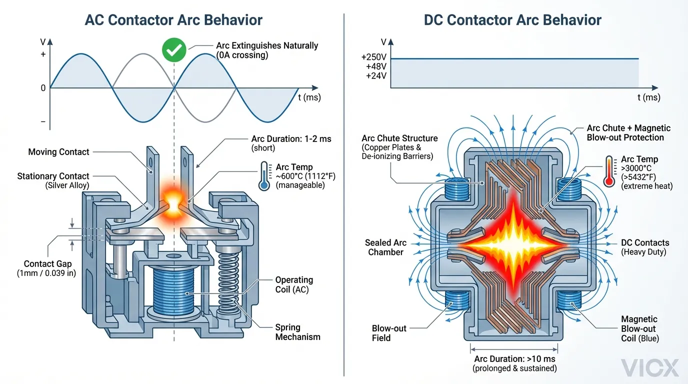
- AC akımı doğal olarak saniyede 100–120 kez sıfıra ulaşır (döngü başına iki kez)
- Kontaklar açıldığında, ark her sıfır geçişte otomatik olarak söner
- Ark bastırma doğası gereği basittir—pahalı mekanizmalara gerek yoktur
Yaygın AC Voltaj Değerleri:
- 120V AC (Kuzey Amerika, konut)
- 230V AC (Avrupa, konut)
- 400V AC / 415V AC (Endüstriyel üç fazlı)
- 480V AC (Endüstriyel Kuzey Amerika)
Tipik AC Uygulamaları:
- HVAC kompresörleri ve klima santralleri
- Aydınlatma kontrol sistemleri
- Elektrikli ısıtıcılar ve direnç yükleri
- İndüksiyon motoru starterleri
- Genel endüstriyel yük anahtarlaması
DC Kontaktörler: Doğru Akım Uygulamaları
DC kontaktörleri, tek yönlü akım akışına sahip devreleri işler—elektronik asla doğal olarak “sıfır geçiş” yapmaz.”
Eşsiz Zorluk:
- Kontaklar açıldığında, arklar süresiz olarak devam eder (kırmak için sıfır geçiş yok)
- Ark, aşırı ısı üreten (>3000°C) sürekli bir plazma kanalı haline gelir
- Isı, feci kontak erozyonuna, bobin hasarına ve yangın riskine neden olur
Gelişmiş Ark Bastırma Mekanizmaları:
- Manyetik üfleme bobinleri: Arkları fiziksel olarak söndürmek için manyetik alanlar kullanın
- Ark olukları: Arkı yalıtılmış bölmeler içinde daha küçük arklar halinde bölün
- Elektronik ark bastırma: Diyotlar veya devreler endüktif enerjiyi dağıtır
- Sağlam kontak malzemeleri: Isıya dayanmak için gümüş alaşımları veya tungsten
Yaygın DC Voltaj Değerleri:
- 12V DC (Otomotiv, küçük yenilenebilir enerji kaynakları)
- 24V DC (Endüstriyel kontrol, PLC devreleri)
- 48V DC (Güneş enerjisi, batarya sistemleri)
- 600V DC (Güneş enerjisi tarlaları, şebeke ölçekli depolama)
- 800V DC (Modern EV şarj sistemleri)
Tipik DC Uygulamaları:
- Güneş fotovoltaik (PV) dizi anahtarlaması
- Batarya enerji depolama sistemi (BESS) yönetimi
- Elektrikli araç (EV) şarjı ve yerleşik sistemler
- DC endüstriyel süreçleri (elektrokaplama, veri merkezleri)
- Yenilenebilir enerji invertör kontrolü
Uyumsuzluğun Feci Sonuçları
| Senaryo | Sonuç | Risk Seviyesi |
|---|---|---|
| DC devresinde AC kontaktör | Ark söndürülemez; kontrolsüz ısı; yangın | KRİTİK |
| AC devresinde DC kontaktör | Aşırı mühendislik, gereksiz maliyet; çalışır ama israf | Küçük |
| Yanlış voltaj değeri | Kontaklarda ark oluşumu; potansiyel yalıtım arızası | KRİTİK |
Ark bastırma mekaniğinin daha derinlemesine anlaşılması için bkz. AC kontaktör bileşenleri ve tasarım mantığı içinde.
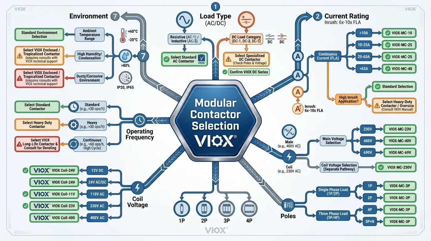
Modüler Kontaktörler için 7 Temel Seçim Kriteri
1. Yük Tipi ve Akım Değeri (#1 Hatası: Boyutlandırma Hataları)
Bu nominal çalışma akımı ($I_e$), kontaktörün sürekli olarak güvenli bir şekilde taşıyabileceği maksimum akımı gösterir. Mühendislerin çoğu ölümcül hataları burada yapar.
Altın Kural: Asla sadece Normal Çalışma Akımını kullanmayın.
Neden? Kalkış Akımı.
Endüktif yükler (motorlar, transformatörler) başladığında, çekerler Çalışma akımlarının 5–10 katı 100–500 milisaniye boyunca. Örnek:
- Motor nominal 10A sürekli
- Başlangıçta kalkış akımı: 75A (7,5× çarpan)
- Gerekli minimum kontaktör değeri: 75A (10A değil)
Kalkış akımını hesaba katmamak, kontak erozyonuna, kaynağa ve bobin aşırı ısınmasına yol açar.
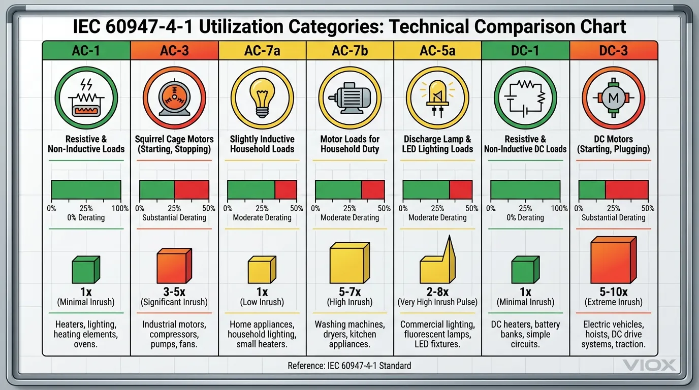
IEC 60947-4-1 Yük Kategorileri (Kullanım Sınıfları):
Standart, anahtarlama görevini belirleyen “kullanım kategorilerini” tanımlar. Bu kategoriler—AC-1, AC-3, AC-7a, AC-7b, AC-5a, DC-1, DC-3—doğru kontaktör boyutlandırması için temeldir:
| Kategori | Yük Tipi | Özellikler | Kontaktör Düşürme |
|---|---|---|---|
| AC-1 | Dirençli (Isıtıcılar, Akkor) | Kalkış yok, kararlı akım | Düşürmeye gerek yok |
| AC-7a | Ev Tipi Dirençli | Isıtıcılar, fırınlar, akkor aydınlatma | ~0% düşürme |
| AC-7b | Ev Tipi Motor | Küçük motorlar, fanlar, pompalar | ~20–30% düşürme |
| AC-3 | Endüstriyel Motor (Sincap kafesli) | Motor çalıştırma ve kontrol | ~30–40% düşürme |
| AC-5a | LED ve Elektronik Yükler | Kapasitif kalkış | ~50% düşürme |
| DC-1 | Dirençli DC (Akü ısıtıcıları) | Kararlı DC, düşük endüktans ($L/R \leq 1ms$) | Düşürme yok |
| DC-3 | DC Şönt Motorlar | Yüksek endüktanslı DC devreleri | ~50% düşürme |
2. Gerilim Değeri: Hem Ana Devre hem de Bobin Gerilimi
Modüler kontaktörlerin iki bağımsız gerilim değeri vardır:
a) Ana Devre Gerilimi ($U_e$):
- Anahtarlanan yükün gerilimi
- Örnek: 230V AC, 48V DC, 400V AC
- Kural: Kontaktör değeri ≥ sistem gerilimi olmalıdır
- Düşük boyutlandırma yalıtım arızasına ve ark oluşumuna neden olur
b) Kontrol Bobini Gerilimi ($U_c$):
- Kontakları kapatmak için kontaktöre enerji veren gerilim
- Ana devre geriliminden bağımsız
- Yaygın bobin değerleri: 12V, 24V, 110V, 230V (AC veya DC)
Örnek Uyuşmazlık:
- 230V AC motorunuz var (ana devre)
- PLC'niz 24V DC çıkışı veriyor (bobin gereksinimi)
- Doğru kontaktör: 230V AC değerinde, 24V DC bobin
Modern Evrensel Bobinler:
Bazı VIOX ve premium kontaktörler şunları içerir: evrensel bobinler geniş voltaj aralıklarında (örn. 12–240V AC/DC) hem AC hem de DC'yi kabul eder. Standart tek voltajlı bobinlere sahip kontaktörlerin aksine, evrensel tasarımlar şunları sağlar:
- Azaltılmış enerji tüketimi (0,5–0,9W tutma gücü)
- Ortadan kaldırılmış bobin uğultusu ve titreşimi
- Yenilenebilir enerji sistemleriyle daha iyi uyumluluk
Daha fazla bilgi edinin kontaktörlerin neden iki voltajı var (kontrol ve yük).
3. Kutuplu Konfigürasyon: Tek veya Çoklu Devreleri Kontrol Etme
Bu kutup sayısı kontaktörün kaç bağımsız devreyi kontrol edebileceğini belirler:
| Kutuplar | Konfigürasyon | Typical Application | Ortak Akım |
|---|---|---|---|
| 1P | Tek fazlı iletken | Isıtma devreleri, temel DC | 16–40A |
| 2P | İki iletken; faz + nötr | Tek fazlı AC, EV şarj cihazları | 20–63A |
| 3P | Üç iletken (tüm fazlar) | Üç fazlı endüstriyel motorlar | 25–100A |
| 4P | Üç faz + nötr | Tıbbi tesisler, kritik sistemler | 25–63A |
Kutuplu Seçim Mantığı:
- Tek fazlı AC (230V ev beslemesi): 1P veya 2P kullanın (2P, nötrü anahtarlayarak daha iyi koruma sağlar)
- Üç fazlı AC (endüstriyel 400V): Minimum 3P kullanın; nötrün anahtarlanması gerekiyorsa 4P kullanın (hastaneler, veri merkezleri). Hakkında bilgi edinin 1 kutuplu ve 2 kutuplu AC kontaktörleri anlama.
- DC akü sistemleri: Genellikle pozitif, negatif veya her ikisini de kontrol edip etmediğinize bağlı olarak 1P veya 2P
- Solar PV: Genellikle 2P (güvenlik için her iki DC iletkeni de anahtarlanır)
4. Bobin Voltajı Eşleştirme ve Gelişmiş Kontrol Entegrasyonu
Bobin, şununla eşleşmelidir: kontrol devresi voltajı aynen:
Standart Bobin Voltajı Seçenekleri:
- 24V DC (Endüstriyel otomasyon, PLC standardı)
- 110V AC (Manuel/mekanik kontrol)
- 230V AC (Bina otomasyonu)
- 12V DC (Otomotiv, küçük sistemler)
Bunun Önemi:
- Küçük boyutlu bobin → zayıf manyetik alan → eksik kontak kapanması → ark oluşumu
- Büyük boyutlu bobin → boşa harcanan enerji, ısı birikimi
- Uyumsuz voltaj → bobin saatler içinde yanar
Modern Akıllı Entegrasyon:
VIOX ve premium üreticiler artık şu özelliklere sahip kontaktörler sunuyor:
- Yardımcı kontak blokları PLC'lere durum geri bildirimi için (1NO+1NC)
- Mekanik kilitlemeler eş zamanlı ileri/geri çalışmayı önleme
- IoT bina otomasyonu için Modbus/BACnet arayüzleri IoT bina otomasyonu için
- Öngörücü bakım kontak aşınmasını izleyen sensörler
Motor kontrollü uygulamalar için, kontaktörlerin şunlarla nasıl entegre olduğunu düşünün: kapsamlı yük koruması için motor koruma devre kesicileri kapsamlı yük koruması için.
5. Çalışma Frekansı: Görev Döngüsü ve Elektriksel Dayanıklılık
Kontaktör ne sıklıkla açılıp kapanıyor?
Elektriksel dayanıklılık “yük altında çevrimler” olarak belirtilir. Üreticiler tipik olarak şunu garanti eder:
| Görev Sınıfı | Anahtarlama Frekansı | Tipik Dayanıklılık | Uygulamalar |
|---|---|---|---|
| Standart | günde <50× | 100.000–300.000 çevrim | HVAC, aydınlatma, genel amaçlı |
| Ağır | günde 50–500× | 500.000–1.000.000 çevrim | Endüstriyel pompa kontrolü, sık çevrim |
| Sürekli | >Günde 500× | 1.000.000+ çevrim | LED kısma, güç faktörü düzeltmesi |
Neden önemli?
Her anahtarlama işlemi mikroskobik kontak erozyonuna neden olur. 100.000 çevrimden sonra:
- Kontak direnci artar
- Ark oluşumu daha belirgin hale gelir
- Bobin ısınması artar
- Arıza yakındır
Maliyet-Fayda:
- Standart hizmet kontaktörü (~$15–30): Ağır çevrim uygulamalarında ~3 yıl sonra arızalanır
- Ağır hizmet kontaktörü (~$25–45): Aynı uygulamada 7–10 yıl dayanır
- ROI: <6 ay (tasarruf edilen değiştirme işçiliği + arıza süresi)
6. Çevresel Faktörler: Sıcaklık, Nem, Toz, Titreşim
Ortam Sıcaklığı:
- Çoğu modüler kontaktör için derecelendirilmiştir – 5°C ila +60°C standart
- Yüksek sıcaklık varyantı mevcuttur: – 5°C ila +80°C (+40°C'nin üzerinde 12% akım azaltımı); ayrıntılı bilgi için bkz. sıcaklık ve rakım için elektriksel azaltma kılavuzu
- Çoklu kontaktörlü kapalı paneller üretir +15–20°C ek ısı
- Termal yönetim: Bırakın 9 mm boşluklar ara modüller kullanarak kontaktörler arasında
IP Koruma Derecelendirmeleri (Giriş Koruması):
| IP Derecesi | Koruma Seviyesi | Uygun Ortamlar |
|---|---|---|
| IP20 | Temasa dayanıklı | Kuru iç mekan panelleri |
| IP40 | Toz direnci | Dış mekan muhafazaları, tozlu depolar |
| IP54 | Toz geçirmez, sıçramaya dayanıklı | Islak odalar, dış mekan alanları |
| IP67 | Temporary immersion | Yeraltı/dalgıç (kontaktörler için nadir) |
Nem ve Rutubet:
- Kontaklar neme maruz kaldığında korozyona uğrar
- Bobin yalıtımı >85% bağıl nemde bozulur
- Çözüm: Sızdırmaz kontaktörler veya IP54+ muhafaza içindeki DIN rayına monte kontaktörler
Titreşim Toleransı:
- Yüksek titreşimli ortamlar (endüstriyel makineler, araçlar) şunlara neden olabilir:
- Gevşek bağlantılar (birincil arıza modu)
- Eksik kontak kapanması
- Artan ark oluşumu
- Azaltma: Titreşim önleyici montaj ayakları kullanın; torku yıllık olarak kontrol edin
7. Güvenlik Özellikleri ve Uyumluluk Standartları
Ark Bastırma Teknolojisi:
- Modern kontaktörler kullanır dahili ark olukları veya manyetik üfleme bobinleri
- Premium modellerde bulunur çift kesmeli kontaklar (ark iki küçük arka ayrılır)
- VIOX BCH8 serisi şunları içerir sessiz çalışma teknolojisi gürültüyü 60% azaltma
Koruyucu Özellikler:
- Manuel geçersiz kılma: Kontrol sistemi arızası sırasında çalışmaya izin verir
- Durum göstergeleri: Kontaktör durumunun görsel onayı (LED, mekanik bayrak)
- Termal aşırı yük koruması: Entegre veya harici rölelerle uyumlu
- Yardımcı kontaklar: Teşhis için kontaktör durumunu PLC'ye geri besleyin
Uyumluluk Standartları (Kuzey Amerika ve Avrupa için Kritik):
| Standart | Uygulama | Temel Gereksinimler |
|---|---|---|
| IEC 61095 | Ev/konut tipi | Temel güvenlik, yalıtım, çalışma döngüleri |
| IEC 60947-4-1 | Endüstriyel modüler kontaktörler | Yük kategorileri, ark bastırma, termal sınırlar |
| UL 508 | Kuzey Amerika endüstriyel panoları | Kesme kapasitesi, termal sınırlar |
| EN 45545-2 | Demiryolu sistemleri | Yangın güvenliği, duman emisyonu |
| ISO 13849-1 | Güvenlik açısından kritik uygulamalar | Zorla yönlendirilen kontaklar, yedeklilik |
IEC yük sınıflandırmasının ayrıntılı anlaşılması için, bkz. IEC 60947-3 kullanım kategorileri kılavuzu ve nasıl olduğunu öğrenin kontaktörler ve röleler güvenlik açısından kritik sistemlerde farklılık gösterir.
Adım Adım Karar Çerçevesi: 6 Adımlı Seçim Süreci
Adım 1: Yük Tipinizi Belirleyin (AC veya DC)
Şu soruyu cevaplayın: Yükünüz alternatif akım mı yoksa doğru akım mı ile besleniyor?
AC Yükleri: Ev/ticari güç şebekeleri, üç fazlı endüstriyel ekipman, HVAC sistemleri
DC Yükleri: Güneş panelleri, batarya sistemleri, elektrikli araçlar, yenilenebilir enerji invertörleri, veri merkezi güç dağıtımı
→ Emin değilseniz, bir multimetre ile voltajı ölçün:
- AC voltajı sürekli dalgalanır (50/60 Hz)
- DC voltajı sabit okunur
Adım 2: Akım Gereksinimlerini Hesaplayın (Ani Akım Dahil)
Adım 2a: Normal Çalışma Akımını (FLA) Bulun
Etiket değerine sahip ekipmanlar için:
- FLA'yı doğrudan ekipman etiketinden okuyun
- Örnek: Motor etiketinde “10A FLA” gösteriliyor”
Üç fazlı AC motorlar için (etiketlenmemişse):
Nerede?
- $P$ = kW cinsinden Güç
- $U$ = Voltaj (Volt)
- $\cos(\phi)$ = Güç faktörü (tipik olarak motorlar için 0,85–0,95)
- $\eta$ = Verimlilik (tipik olarak motorlar için 0,85–0,92)
Adım 2b: Ani Akımı Tahmin Edin
| Yük Tipi | Ani Akım Çarpanı | Örnek |
|---|---|---|
| Dirençli (ısıtıcılar) | 1–1.5× | 10A yük = 10A ani akım |
| Akkor aydınlatma | 1–2× | 10A yük = 10–20A ani akım |
| Motor (yumuşak başlangıç) | 3–5× | 10A yük = 30–50A ani akım |
| Motor (doğrudan şebeke bağlantısı) | 5–10× | 10A yük = 50–100A ani akım |
| LED sürücü/elektronik | 2–8× | 10A yük = 20–80A ani akım |
| Transformatör | 8–12× | 1A yük = 8–12A ani akım |
Adım 2c: Yük Kategorisi Düşürmesini Uygulayın
Yukarıdaki “Yük Tipi ve Akım Değeri” bölümündeki tabloya bakın.
Adım 3: Voltaj Gereksinimlerini Doğrulayın
Her ikisini de kaydedin:
- Ana devre voltajı (anahtarlanan yük): örneğin, 230V AC, 48V DC
- Kontrol bobini voltajı (PLC veya kontrol sistemi çıkışı): örneğin, 24V DC, 110V AC
Kontaktör veri sayfasının her iki değeri de belirttiğini doğrulayın.
Adım 4: Kutuplu Konfigürasyonu Seçin
Karar Ağacı:
Yük tek fazlı mı yoksa üç fazlı mı?
Adım 5: Çalışma Ortamını ve Görev Döngüsünü Değerlendirin
Kontrol Listesi:
- Ortam sıcaklığı aralığı: ___°C ila ___°C
- Nem: Kuru / Nemli / Islak ortam?
- Toz/kirlenme seviyesi: Yok / Hafif / Yoğun?
- Titreşim ortamı: Yok / Orta / Yüksek?
- Anahtarlama frekansı: Günde ___ kez
- Gürültü kontrolüne ihtiyaç var mı? Evet / Hayır
- Panoda mevcut alan: ___ mm
Sonuçlar:
- Yüksek sıcaklık → Ağır hizmet tipi seçin, güç azaltma gerekli
- Yüksek nem → Sızdırmaz kontaktör veya IP54+ muhafaza
- Yüksek titreşim → Titreşim önleyici montaj
- Sık anahtarlama → Ağır hizmet tipi veya katı hal kontaktör
- Gürültüye duyarlı alan → Katı hal veya “sessiz tip” kontaktör
Adım 6: Özel Gereksinimleri Gözden Geçirin
Dikkate Alınması Gereken Ek Özellikler:
- Yardımcı kontak blokları (PLC geri bildirimi için)
- Mekanik kilitleme (ters çevirme uygulamaları için)
- Entegre termik aşırı yük rölesi
- Akıllı/IoT izleme özelliği
- Acil durum operasyonu için manuel geçersiz kılma
- Belirli sertifika (UL, CE, CSA)
Kontaktör Seçim Karşılaştırma Tablosu: Hızlı Referans
Uygulamanıza hızlıca çapraz referans vermek için bu tabloyu kullanın:
| Uygulama | Yük Tipi | Önerilen Voltaj | Kutuplar | Geçerli Aralık | Görev | Özel Notlar |
|---|---|---|---|---|---|---|
| HVAC Kompresörü | AC-3 Motor | 230V/400V AC | 3P | 15–40A | Ağır | Ani akım için yumuşak başlatma ekleyin |
| Ev Tipi EV Şarj Cihazı | AC-1/AC-7a | 230V AC | 2P | 16–32A | Standart | Bobin: 24V DC önerilir |
| Solar PV Dizi Anahtarı | DC-1 | 600V DC | 2P | 20–63A | Standart | Ark bastırma kritik |
| Endüstriyel Aydınlatma | AC-7a | 230V/400V AC | 1P–3P | 16–63A | Ağır | Çoklu bölgeler → çoklu kontaktörler |
| Havuz Pompası | AC-3 Motor | 230V AC | 1P | 10–16A | Standart | 1.5× ani akım faktörü; bakınız yıldız-üçgen yol verme bağlantısı yumuşak başlatma seçenekleri için |
| Veri Merkezi PDU | AC-1 | 400V AC | 3P | 63–100A | Ağır | Modbus entegrasyonu önerilir |
| EV Batarya Ayırma | DC-3 Motor | 48–800V DC | 2P | 50–200A | Standart | Özel ark bastırma gerekli |
| Akıllı Ev Rölesi | AC-7a | 230V AC | 1P | 10–20A | Standart | Evrensel bobin tercih edilir (gürültü azaltma) |
Gerçek Dünya Uygulama Örnekleri: Teoriden Pratiğe
Örnek 1: Üç Fazlı Endüstriyel HVAC Sistemi
Senaryo:
5 katlı bir ofis binası için yeni bir klima santrali kuruyorsunuz. Motor etiketinde şunlar yazıyor:
- Güç: 7.5 kW
- Gerilim: 400V üç fazlı AC
- FLA: 15A
- Yol verme yöntemi: Doğrudan şebekeye (DOL)
Kararlarınız:
- Yük Tipi: AC-3 (endüksiyon motoru)
- Ani Akım: 15A × 7 = 105A (DOL başlatma)
- Kontaktör Değerlendirmesi: Minimum 105A → Seç 125A kontaktör
- Ana Devre Gerilimi: 400V AC ✓
- Bobin Gerilimi: Binada 24V DC PLC var → Belirtin 24V DC bobin
- Kutuplar: Üç fazlı → 3P konfigürasyonu
- Görev Döngüsü: HVAC döngüleri günde 3–5× → Standart görev kabul edilebilir
- Çevre: İç mekan, klimalı alan, toz/nem yok
Önerilen Kontaktör:
- Tip: AC kontaktör, 125A, 400V AC, 3P, 24V DC bobin
- Örnek: VIOX BCH8-63/40 (63A AC-3 nominal = ~110A efektif kapasite)
- Yardımcı kontaklar: BMS'ye durum geri bildirimi için 1NO+1NC
Örnek 2: Konut Tipi Güneş Enerjisi Batarya Sistemi
Senaryo:
10kWh depolama alanına sahip bir ev için 48V DC batarya yedekleme sistemi tasarlıyorsunuz. Batarya ayırma kontaktörü şunları yapmalıdır:
- Batarya grubundan invertöre 48V DC'yi kontrol etme
- 200A sürekli şarj/deşarj akımını taşıma
- Bağlantı durumunu göstermek için durum LED'i içerir
- Güvenlik kodu gereksinimlerini karşılama
Kararlarınız:
- Yük Tipi: DC-1 (rezistif) / DC-3 (pompa yükleri varsa motor)
- Sürekli Akım: 200A
- Kontaktör Değerlendirmesi: 200A × 1.25 güvenlik faktörü = Minimum 250A
- Ana Devre Gerilimi: 48V DC ✓
- Bobin Gerilimi: İnvertör 24V DC sinyali sağlar → Belirtin 24V DC bobin
- Kutuplar: Hem (+) hem de (–) iletkenler ayrılmalıdır → 2P konfigürasyonu
- Görev Döngüsü: Düşük frekanslı anahtarlama (günde bir kez) → Standart görev kabul edilebilir
- Ark Bastırma: KRİTİK – DC, sağlam ark bastırma gerektirir (manyetik üfleme veya ark olukları)
Önerilen Kontaktör:
- Tip: DC kontaktör, 250A, 48V DC, 2P, 24V DC bobin, sağlam ark bastırma
- Örnek: Manyetik üfleme bobinine sahip VIOX özel DC kontaktörü
- Yardımcı kontaklar: Ev otomasyon sistemine durum geri bildirimi
- Motor gücüne göre kontaktör seçimi hakkında daha fazla bilgi için bkz. motor gücüne göre kontaktörler ve devre kesiciler nasıl seçilir
Örnek 3: Modern Ofiste LED Aydınlatma Kontrolü
Senaryo:
50 masalı açık bir ofiste otomatik aydınlatma kontrolüne (hareketle etkinleştirilen) ihtiyaç vardır. Her aydınlatma bölgesi 230V AC'den 5A çeker. Sessizlik gereksinimi: <20dB (kontaktörlerden duyulabilir uğultu yok).
Zorluk: LED sürücülerde büyük kapasitif ani akım vardır (5–8× yük akımı).
Kararlarınız:
- Yük Tipi: AC-5a (LED elektronik yük)
- Sürekli Akım: Bölge başına 5A
- Ani Akım: 5A × 7 = 35A (kapasitif ani akım)
- Kontaktör Değerlendirmesi: Minimum 35A → 40–50A seçin (AC-5a için azaltma)
- Ana Devre Gerilimi: 230V AC ✓
- Bobin Gerilimi: Hareket sensörü 12V DC çıkışı verir → Belirtin evrensel 12–240V AC/DC bobin (uğultuyu ortadan kaldırır)
- Kutuplar: Tek fazlı → 1P veya 2P (nötr anahtarlama için 2P)
- Gürültü Kontrolü: Katı hal kontaktör veya “Sessiz Tip” elektromanyetik kontaktör gereklidir
- Anahtarlama Frekansı: Yüksek (günde 10–20×) → Ağır hizmet tipi derecelendirme tercih edilir
Önerilen Kontaktör:
- Tip: AC sessiz tip kontaktör, 40A, 230V AC, 1P, evrensel bobin
- Alternatif: Katı hal AC kontaktör (sıfır geçiş teknolojisi, tamamen sessiz)
- Yardımcı kontaklar: Hareket sensörü denetleyicisine geri bildirim için 1NC
Yaygın Seçim Hataları ve Bunlardan Nasıl Kaçınılır?
| Hata | Sonuç | Önleme |
|---|---|---|
| DC için AC kontaktör kullanma | Kontrolsüz ark, yangın, ekipman hasarı | Sipariş vermeden önce DAİMA yük tipini doğrulayın |
| Ani akım için yetersiz boyutlandırma | Kontak kaynağı, bobin yanması, panel yangını | Motorlar için 5–10× çarpanı hesaba katın |
| Ortam sıcaklığını göz ardı etmek | Erken bobin arızası, azalmış kontak ömrü | Ortam sıcaklığını kontrol edin; azaltma uygulayın |
| Uyumsuz bobin voltajı | Zayıf manyetik alan, eksik kapanma, ark oluşumu | PLC/kontrol sinyal voltajının bobinle eşleştiğini doğrulayın |
| Yardımcı kontak yok | Kontrol sistemine geri bildirim yok, teşhis imkansız | Tüm kritik devreler için yardımcı kontakları belirtin |
| Yetersiz kutup sayısı | Tek fazlı AC'de nötr korumasız | Konut AC için minimum 2P kullanın |
| Görev döngüsünü göz ardı etmek | Yüksek çevrim uygulamalarında erken arıza | >100 çevrim/gün için ağır hizmet tipi seçin |
| DIN rayında termal aralık yok | Kümülatif ısı, azaltmaya ve arızalara neden olur | Yüksek akımlı kontaktörler arasında 9 mm boşluk bırakın |
Kurulum, Bakım ve Devreye Alma En İyi Uygulamaları

Doğru kurulum çok önemlidir. Muayene ve bakım konusunda kapsamlı rehberlik için, endüstriyel kontaktör bakım ve inceleme kontrol listesine bakın.
Kurulum Öncesi Kontrol Listesi
- Kontaktör özelliklerinin tasarımla eşleştiğini doğrulayın (voltaj, akım, kutuplar, bobin)
- DIN rayının yeterli alana sahip olduğunu doğrulayın (ünite başına 18–36 mm + termal aralık)
- Tüm kontrol kablolarının önceden yönlendirildiğini ve etiketlendiğini kontrol edin
- Kontaktörün yukarısındaki devre kesicinin doğru şekilde derecelendirildiğinden emin olun
- Çevresel koşulları doğrulayın (sıcaklık, nem, toz)
- Tüm personelin kalifiye ve KKD ile donatıldığından emin olun
Kurulum Adımları
- DIN Rayına Monte Edin: Kontaktörü 35 mm DIN rayına (IEC 60715) oturtun
- Yönlendirmeyi Doğrulayın: Kontak terminalleri aşağı bakar; bobin terminallerine erişilebilir
- Termal Aralık Bırakın: Bitişik bileşenlere 9 mm boşluk (kontaktörler >20A için ara modüller kullanın)
- Ana Devre Kablolaması:
- Devre akım değerine göre bakır iletkenler kullanın
- Önerilen torku uygulayın (aşağıdaki tork tablosuna bakın)
- DC devreler için polariteyi iki kez kontrol edin
- Kontrol Devresi Kablolaması:
- EMI'yi en aza indirmek için düşük voltajlı kontrol kablolarını bükün
- Yüksek akımlı iletkenlerden uzak tutun
- Bobin voltajının beslemeyle tam olarak eşleştiğini doğrulayın
- Yardımcı Kontaklar (varsa):
- Durum geri bildirimi için PLC/izleme sistemine bağlayın
- Enerji vermeden önce multimetre ile test edin
Terminal Tork Özellikleri
| Güncel Değerlendirme | Kablo Boyutu (mm²) | Tork (N·m) | Tork (in-lb) |
|---|---|---|---|
| 16A | 1.5–2.5 | 0.5 | 4.4 |
| 20A | 2.5–4 | 0.8 | 7 |
| 25A | 4–6 | 0.8 | 7 |
| 32A | 6–10 | 1.5 | 13 |
| 40A | 10–16 | 2 | 18 |
| 63A | 16–25 | 3.5 | 31 |
| 100A | 35–50 | 6 | 53 |
Kritik: Düşük torklu bağlantılar, kontaktör arızalarının ve panel yangınlarının en büyük nedenidir. Daima kalibre edilmiş bir tork tornavidası kullanın.
Devreye Alma Testleri
- Bobin Direnci Testi:
- Bobin terminalleri arasında multimetre ile ölçün
- Beklenen: 5–20 ohm (tipik 230V bobin)
- 5Ω'nin altında → Bobin kısa devre yapmış, hemen değiştirin
- Kontak Süreklilik Testi:
- Ana kontaklar kapalı (enerjisiz) → 0.1–0.5Ω okunmalıdır
- İyi kontak basıncı ve düşük direnci gösterir
- 1Ω'un üzerinde → Kontakları temizleyin veya araştırın
- Gerilim Düşümü Testi:
- Nominal yük akımı akarken → Kapalı kontaklar üzerindeki gerilim düşümünü ölçün
- Tipik: Nominal akımda <100mV
- 200mV'un üzerinde → Kontak bozulması tespit edildi
- Bobin Enerjilendirme Testi:
- Bobini nominal gerilimle enerjilendirin
- Belirgin bir “klik” sesi dinleyin (kontaklar kapanıyor)
- Bobin terminallerindeki gerilimi ölçün (besleme ±'una uymalıdır)
Ayrıntılı test prosedürleri için bkz. beceri temelli bir kılavuzla kontaktör nasıl test edilir. Yaygın sorunların giderilmesi için bkz. uğultu, bobin arızası ve tıklama sorunları için kontaktör sorun giderme kılavuzu.
Bakım Programı
| Ara | Eylem | Amaç |
|---|---|---|
| Aylık | Görsel inceleme | Ark izlerini, korozyonu, gevşek kabloları tespit edin |
| Üç ayda bir | Termal görüntüleme (IR kamera) | Zayıf bağlantıları gösteren sıcak noktaları belirleyin |
| Altı ayda bir | Temas direnci ölçümü | Kontak bozulmasını erken tespit edin |
| Yıllık | Tork doğrulama | Bağlantıların sıkı kaldığından emin olun |
| İki yılda bir | Ağır hizmette ise tam değiştirme | Arızadan önce önleyici bakım |
SSS: Mühendislerin Modüler Kontaktör Seçerken Sorduğu 10 Soru
S1: Bir DC kontaktörü bir AC devresinde kullanabilir miyim?
C: Teknik olarak evet, ancak israf olur. 48V DC değerindeki bir kontaktör 230V AC devresinde çalışır (AC, ark söndürmeye yardımcı olan sıfır geçişlere sahiptir), ancak ihtiyacınız olmayan yetenekler için 2–3 katı maliyet ödersiniz. AC uygulamaları için AC kontaktörleri kullanın.
S2: Nominal akım ve kesme kapasitesi arasındaki fark nedir?
A: Nominal akım kontaktörün taşıdığı maksimum sürekli akımdır (örneğin, 63A). Kesme kapasitesi güvenli bir şekilde kesebileceği maksimum akımdır (örneğin, 6kA). Kesme kapasitesi, kısa devrelere karşı koruma için kritiktir. Her zaman her iki değeri de doğrulayın.
S3: Yardımcı kontaklara ihtiyacım var mı?
C: Evet, herhangi bir kritik veya ağ bağlantılı sistem için. Yardımcı kontaklar şunları sağlar:
- PLC/BMS'ye durum geri bildirimi (kontaktörün kapalı olduğunun onayı)
- Tanılama verileri (arızaları gidermeye yardımcı olur)
- Kilitleme (ters uygulamalar için güvenlik)
- Maliyet: +5–10$/ünite; Değer: Feci arızaları önler
S4: Kontaktör bobini arızasına ne sebep olur?
C: En önemli 3 neden:
- Gerilim uyumsuzluğu (örneğin, 24V bobine 12V verme)
- Aşırı ısınma (yetersiz termal aralık, ortam sıcaklığı çok yüksek)
- Nem girişi (nemli ortamlarda yoğuşma)
Azaltma: Gerilimi doğrulayın, termal aralığı koruyun, nemli ortamlarda yalıtımlı kontaktörler kullanın.
S5: Modüler kontaktörler tipik olarak ne kadar dayanır?
C: Normal koşullar altında:
- Standart hizmet elektromanyetik: 5–8 yıl (~100.000 çevrim)
- Ağır hizmet elektromanyetik: 8–12 yıl (~500.000–1.000.000 çevrim)
- Katı hal: 10–15 yıl (mekanik aşınma yok; kapasitörlerle sınırlı)
Ömür, yük tipine, sıklığına ve ortama büyük ölçüde bağlıdır.
S6: “Sessiz tip” veya “uğultusuz” kontaktör nedir?
C: AC bobinleri kullanan kontaktörler, titreşen manyetik devrelerden 50/60Hz “uğultu” üretir. “Sessiz tipler” şunları kullanır:
- Elektronik bobinler (dahili doğrultucu ile çalışır) → uğultuyu ortadan kaldırır
- Manyetik sönümleme sistemleri → titreşim gürültüsünü emer
- Tipik olarak gürültüyü azaltır (yaklaşık 40dB'den <20dB'ye)
Ofisler, hastaneler, konutlar için gereklidir.
S7: Daha yüksek akım kapasitesi için birden fazla kontaktörü paralel bağlayabilir miyim?
A: Şiddetle tavsiye edilmez. Kontaktörler paralel olduğunda, kontak direncindeki küçük farklılıklar eşit olmayan akım dağılımına neden olabilir, bu da daha düşük dirençli ünitenin aşırı ısınmasına ve arızalanmasına yol açar. Bunun yerine, yeterli değerde tek bir kontaktör seçin.
S8: Modüler ve geleneksel (cıvatalı) kontaktörler arasındaki fark nedir?
A:
- Modüler: DIN rayına monte edilmiş, 18–36 mm genişliğinde, kompakt, konut/ticari standart. Karşılaştırarak daha fazla bilgi edinin modüler kontaktörler ve geleneksel kontaktörler.
- Cıvatalı: Daha büyük, cıvatalar/saplamalarla panele monte edilmiş, 100–200A+, endüstriyel/tesis sınıfı
Modüler, modern dağıtım panoları için tercih edilir; cıvatalı, büyük güç uygulamaları için ayrılmıştır.
S9: Yüksek ortam sıcaklıklarında termal düşüşü nasıl ele alırım?
C: 40°C'nin üzerindeki ortam sıcaklığında:
- Düşürme faktörü tipik olarak 40°C üzerindeki her °C için %2–3
- Örnek: 60°C ortam sıcaklığında 63A kontaktör → 63A × (1 – 0.02 × 20) = 63A × 0.6 = 37.8A efektif değer
Çözüm: Daha büyük kontaktör kullanın veya havalandırmayı iyileştirin (zorlamalı soğutma fanları, daha büyük kabin).
S10: IEC ve UL standartları arasındaki fark nedir?
A:
- IEC 61095 (Avrupa/global): Ev tipi modüler kontaktörleri tanımlar; UL'den daha az talepkar
- UL 508 (Kuzey Amerika): Endüstriyel kontrol ekipmanlarını tanımlar; daha katı kesme kapasitesi ve termal gereksinimler
- IEC 60947-4-1 (Global endüstriyel): Modüler ve endüstriyel kontaktörler; yük kategorilerini tanımlar
Bölgenizin gereksinimlerini daima doğrulayın; Kuzey Amerika panelleri UL sertifikası gerektirir.
Temel Çıkarımlar: 10 Maddelik Ana Kontrol Listesi
- 1. Önce Yük Tipini Eşleştirin: AC veya DC—bu EN kritik karardır. Bir hata yangınlara neden olabilir.
- 2. Ani Akımı Faktör Edin: Asla sadece çalışma akımına göre boyutlandırma yapmayın. Motorlar, çalıştırma sırasında FLA'larının 5–10 katı akım çekebilir.
- 3. Her İki Voltajı da Doğrulayın: Ana devre voltajı VE bobin voltajı spesifikasyonlarla eşleşmelidir.
- 4. IEC Yük Kategorilerini Kullanın: Uygun düşürme faktörlerini uygulamak için AC-1, AC-3, AC-7a, DC-1, DC-3'e başvurun.
- 5. Doğru Kutupları Seçin: Basit devreler için 1P; tek fazlı güvenlik için 2P; üç fazlı için 3P; kritik nötr anahtarlama için 4P.
- 6. Yardımcı Kontakları Dahil Edin: Durum geri bildirimi, teşhis edilmemiş arızaları önler ve akıllı entegrasyonu sağlar.
- 7. Termal Aralığı Planlayın: Kümülatif aşırı ısınmayı önlemek için yüksek akımlı kontaktörler arasında 9 mm boşluk bırakın.
- 8. Uygulamaya Göre Görevi Eşleştirin: Ara sıra anahtarlama için standart görev; sık döngü için ağır hizmet; sessiz/yüksek frekans gereksinimleri için katı hal.
- 9. Sertifikasyonu Belirtin: Bölgesel standartlara (IEC, UL, CE, CSA) uygunluğu sağlayın.
- 10. Uygun Kurulum ve Teste Yatırım Yapın: Yetersiz sıkılmış bağlantılar, panel yangınlarının 1 numaralı nedenidir. Kalibre edilmiş aletler kullanın ve yüklemeden önce devreye alın.
Sonuç: Karışıklıktan Güvene
Doğru modüler kontaktörü seçmek artık tahminden ibaret değil. Bu sistematik 6 adımlı seçim çerçevesiyle (yük tipini belirleme, akım gereksinimlerini hesaplama, voltajları doğrulama, kutupları seçme, ortamı değerlendirme ve özel ihtiyaçları gözden geçirme) çalışarak, yıllarca güvenli ve güvenilir bir şekilde çalışacak bir kontaktörü güvenle seçebilirsiniz.
Kötü seçimin sonuçları ağırdır: yangınlar, ekipman hasarı, maliyetli arıza süresi, güvenlik sorumluluğu. Ancak bu kılavuzun ilkeleri, standart referansları (IEC 60947-4-1, IEC 61095) ve VIOX'un mühendislik uzmanlığı ile donanmış olarak, deneyimli mühendisleri bile tuzağa düşüren yaygın tuzaklardan kaçınmaya hazırsınız.
