On this page
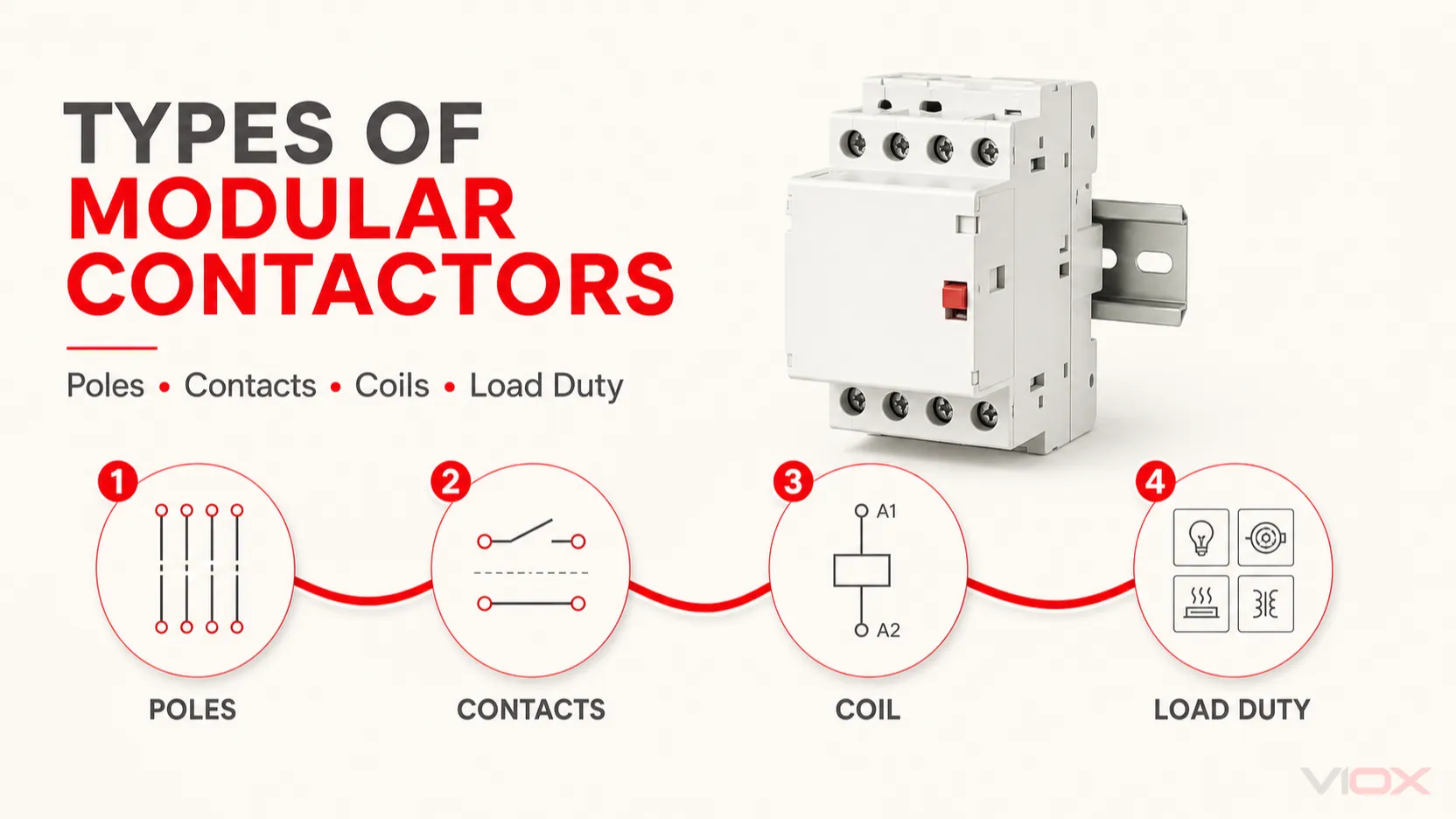
The main types of modular contactors are distinguished by pole count, contact configuration, coil supply, operating mode, and load-duty rating. These classifications describe different parts of the same device. For example, a product may be a four-pole, four-normally-open, 230 V AC-coil modular contactor rated for a specified AC-7a load.
For most projects, the correct question is not simply “Which type is best?” It is: Which combination of poles, contacts, coil, utilization category, and operational features matches the circuit?
Modular Contactor Types at a Glance
| Classification | Common options | What the choice controls |
|---|---|---|
| Number of poles | 1P, 2P, 3P, 4P | How many conductors are switched together |
| Contact configuration | NO, NC, or combinations such as 1NO+1NC and 2NO+2NC | Whether each power path is open or closed when the coil is de-energized |
| Coil supply | AC or DC, at a specified control voltage | Compatibility with the control circuit |
| Operating mode | Automatic, manual override, or product-specific maintained control | How the contactor is commanded or temporarily operated |
| Acoustic design | Standard or low-noise/silent type | Suitability for occupied or noise-sensitive areas |
| Load duty | AC-7a, AC-7b, AC-7c, AC-7d, or another manufacturer-specified category | The type of load and switching stress the device can handle |
This classification matrix is more useful than dividing all products into “AC contactors” and “DC contactors.” The coil supply and the switched load are separate specifications. A contactor with a DC coil may still switch an AC load when the manufacturer provides the appropriate rating.
What Makes a Contactor “Modular”?
A modular contactor is a compact switching device designed for installation in a modular DIN-rail distribution board or control panel. In a typical electromechanical design, applying the specified control voltage to coil terminals A1 and A2 creates a magnetic field. The mechanism changes the state of the main contacts, switching power to the connected load. When the coil is de-energized, a return mechanism restores the normal contact state.
The modular form affects mounting, panel space, terminal access, accessories, and thermal arrangement. It does not remove the need for coordinated short-circuit and overload protection. A contactor controls a circuit; it is not a substitute for a circuit breaker, fuse, or required overload-protection device.
For a broader introduction to construction and wiring, see what a modular contactor is and how it works.
Types by Pole Count: 1P, 2P, 3P, and 4P
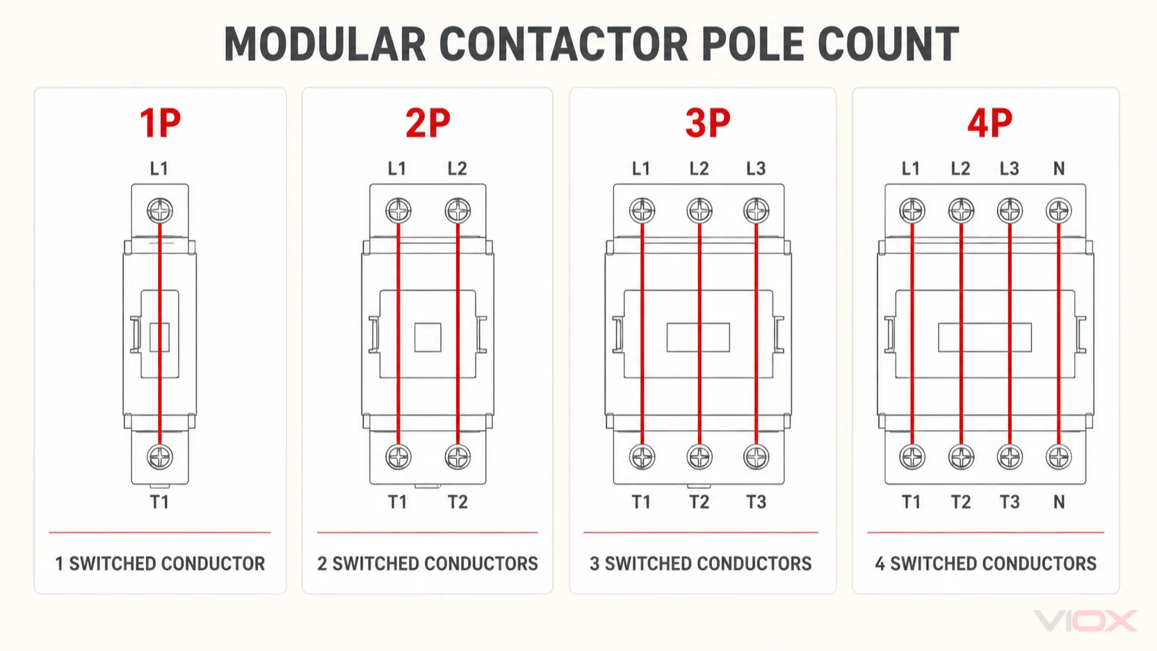
Pole count tells you how many main current paths the contactor operates together. It does not, by itself, identify whether those paths are normally open or normally closed.
| Pole count | Conductors switched | Typical application pattern | Selection boundary |
|---|---|---|---|
| 1P | One conductor | Simple single-circuit load control | Use only where switching one conductor is permitted by the circuit design and applicable rules |
| 2P | Two conductors | Single-phase loads or circuits requiring two switched conductors | Confirm whether the required arrangement is 2NO, 2NC, or 1NO+1NC |
| 3P | Three conductors | Three-phase loads without a switched neutral | Verify that the device has the correct load-duty rating, especially for motors |
| 4P | Four conductors | Three-phase plus neutral or another four-conductor switching scheme | Neutral switching must follow the system design and applicable local rules |
1P Modular Contactors
A single-pole modular contactor switches one conductor. It can suit a simple lighting, heating, or control application where the circuit arrangement allows single-conductor switching. Do not assume that a compact 1P device is appropriate merely because the load is single phase; isolation and conductor-switching requirements depend on the installation.
2P Modular Contactors
A two-pole contactor operates two current paths simultaneously. It is commonly considered for single-phase loads when two conductors must be switched. Buyers should read the complete contact notation: 2NO and 1NO+1NC are both two-pole arrangements, but they behave differently.
3P Modular Contactors
A three-pole contactor is commonly used to switch the three line conductors of a three-phase circuit. Pole count alone does not qualify it for motor duty. For a fan, pump, or compressor, check the applicable motor-load rating and starting conditions rather than relying on the general current value printed on the device.
4P Modular Contactors
A four-pole contactor switches four conductors together. Possible uses include a three-phase system with a switched neutral, but the correct neutral arrangement depends on the earthing system, circuit design, switching sequence, and local requirements. A fourth pole is not automatically an auxiliary contact; it may be a full-rated main pole.
Types by Contact Configuration: NO, NC, and Mixed Contacts
“Normally open” and “normally closed” describe contact state when the coil is de-energized.
- NO (normally open): the power path is open until the contactor is energized. This is common for loads that should remain off when the control signal is absent.
- NC (normally closed): the power path is closed when the coil is de-energized and opens when the coil is energized.
- Mixed configuration: one housing may contain both NO and NC main paths, such as 1NO+1NC or 2NO+2NC, when the product family provides that arrangement.
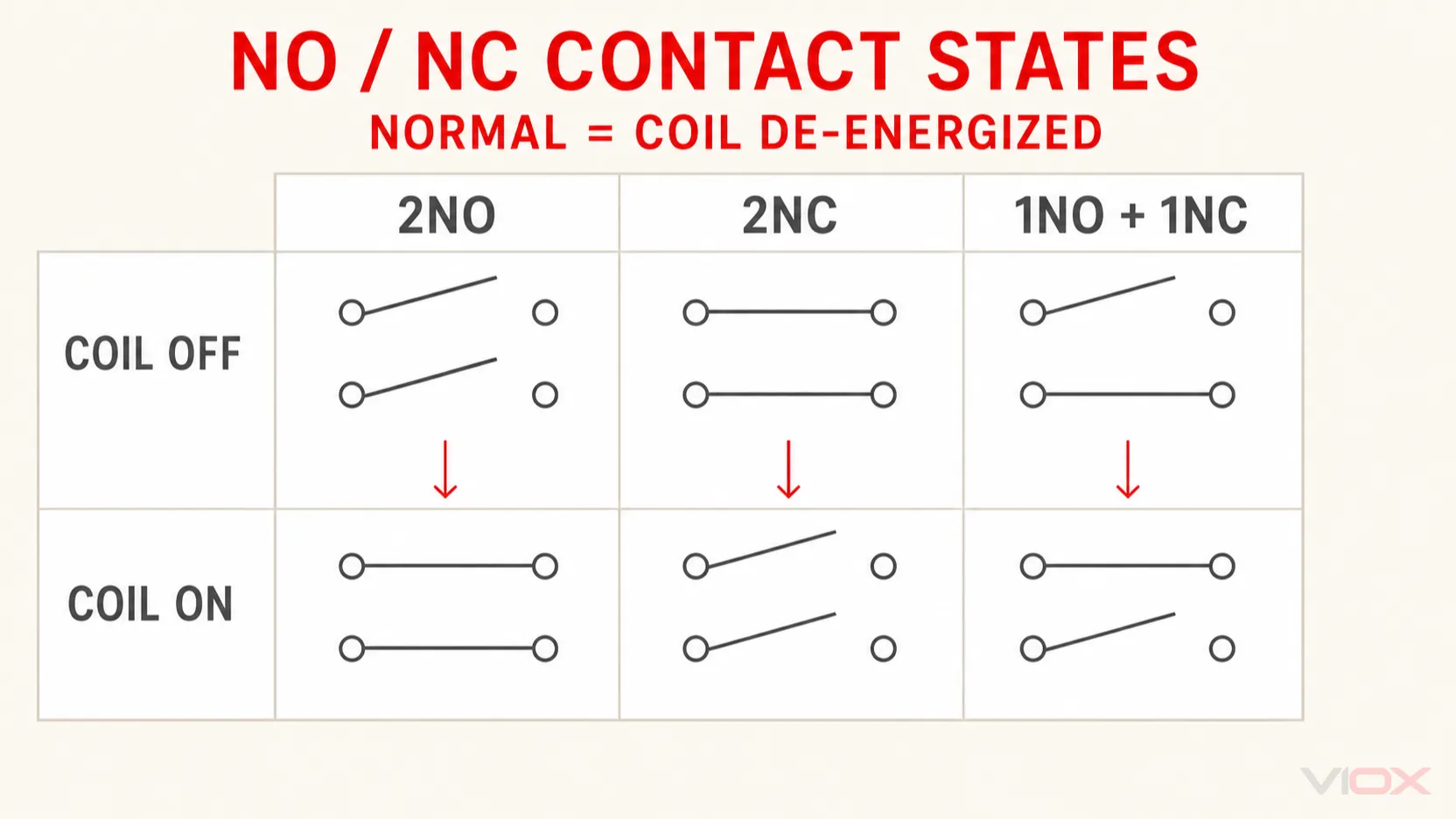
Contact configuration must not be confused with auxiliary contacts. A main contact carries the rated load within its specified duty. An auxiliary contact is generally intended for signaling, holding, interlocking, or controller feedback and must be applied within its own rating.
Types by Coil Supply: AC-Coil and DC-Coil Contactors
The coil must match the control supply, including voltage, AC or DC type, and AC frequency where applicable. The coil voltage may be completely different from the voltage switched by the main contacts.
| Coil type | Often selected when | What to verify |
|---|---|---|
| AC coil | The control circuit supplies AC directly | Nominal voltage, frequency, allowable operating range, inrush and holding requirements |
| DC coil | A programmable logic controller, power supply, battery-backed circuit, or DC control bus provides the command | Nominal voltage, polarity when specified, consumption, and any integrated suppression |
| Electronic or wide-range coil | The product family supports a broader control range or reduced acoustic noise | Exact input range, AC/DC compatibility, leakage-current sensitivity, and manufacturer instructions |
Do not infer the switched-load type from the coil. “24 V DC coil” describes the control input, not permission to interrupt a 24 V DC power load. DC load switching requires an explicit DC operational rating. The broader distinction is explained in the AC versus DC contactor guide.
Standard, Low-Noise, and Manual-Override Types
Standard Electromagnetic Modular Contactors
These use an electromagnetic mechanism and mechanically operated power contacts. They are suitable when the published load ratings, operating frequency, installation conditions, and acoustic characteristics match the application.
Low-Noise or “Silent” Modular Contactors
Low-noise products are useful in homes, offices, hotels, hospitals, and other occupied spaces where coil hum or switching sound matters. “Silent” is not a universal technical construction. Depending on the series, the design may use an electronic coil circuit, a DC magnet system, or another noise-reduction method while retaining mechanical main contacts.
Check the manufacturer’s acoustic description and control-input requirements. Do not assume that a silent modular contactor is a solid-state relay or that it produces no mechanical switching sound under every condition.
Semiconductor contactors are a separate switching family and should not be treated as interchangeable with IEC 61095 electromechanical installation contactors. IEC 60947-4-3:2020 covers semiconductor controllers and semiconductor contactors for non-motor loads on circuits not exceeding 1,000 V AC within that standard’s scope.
Manual-Override Modular Contactors
Some products include a front selector or control lever with positions such as automatic, off, or temporarily on. This can help with commissioning or local control, depending on the model. The override does not automatically provide isolation, lockout capability, or emergency switching. Its permitted operating modes must be confirmed from the product instructions.
Types by Load Duty: AC-7a, AC-7b, AC-7c, and AC-7d
The utilization category is often more important than the nominal ampere value. Within the scope of IEC 61095:2023, AC-7 categories distinguish different switching duties for household and similar applications.
| Category | General load context | Common examples | Selection implication |
|---|---|---|---|
| AC-7a | Slightly inductive or resistive loads in household and similar applications | Resistance heating and suitable lighting loads | Select from the manufacturer’s AC-7a rating at the actual operating voltage |
| AC-7b | Motor loads in household and similar applications | Fans, pumps and small compressors | Use the published AC-7b motor rating and evaluate starting and switching duty |
| AC-7c | Control of compensated electric-discharge lamps | Applicable compensated discharge-lighting circuits | Use the exact model’s AC-7c rating and manufacturer lighting-load data |
| AC-7d | Switching of LED lamps | LED luminaires and LED-driver loads within the published rating | Verify an AC-7d or another explicit manufacturer-published LED-load rating; do not select from AC-7a current alone |
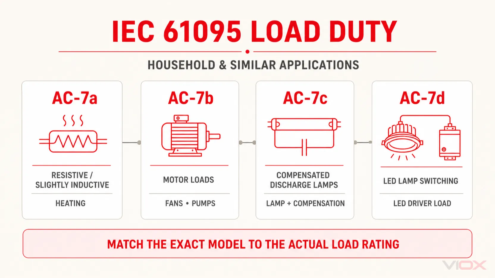
A product can have a higher AC-7a rating than AC-7b rating because motor starting and interruption impose different electrical stress. Schneider Electric’s Acti9 iCT selection guidance likewise separates AC-7a and AC-7b ratings, while its motor-application guidance notes that not every model in a modular range necessarily carries an AC-7b rating.
IEC 61095:2023 added AC-7d along with requirements and tests for LED-lamp switching, including making, breaking and conventional operational performance. LED drivers can produce substantial inrush, so an AC-7a rating should not be used as a substitute for verified LED-load data.
For a focused engineering explanation, see AC-7a versus AC-7b modular contactor selection.
IEC 61095:2023 Scope Boundary
IEC 61095:2023 is not an unlimited standard for every device marketed as a modular contactor. Its publicly stated scope covers:
- electromechanical air-break contactors;
- household and similar purposes;
- main circuits not exceeding 440 V AC between phases;
- rated operational current not exceeding 63 A for AC-7a;
- rated operational current not exceeding 32 A, or the corresponding rated-power expression, for AC-7b, AC-7c and AC-7d; and
- rated conditional short-circuit current not exceeding 6 kA.
Products outside that scope—including higher-duty industrial applications or different switching technologies—may fall under IEC 60947-4-1, IEC 60947-4-3, another applicable standard, or a combination of product and assembly requirements. The relevant standard and certification must be verified for the exact model and application.
Application-Based Selection Matrix
| Application | Likely configuration starting point | Critical checks before selection |
|---|---|---|
| Resistance heating | 1P or 2P, usually NO, AC-7a where applicable | Load current at voltage, switching frequency, enclosure temperature and required conductor switching |
| Lighting circuits | Pole count matched to circuit, normally open unless the control strategy requires otherwise | Lamp/driver inrush, utilization rating, number of controlled circuits and switching frequency; for LED lighting, verify AC-7d or another explicit manufacturer-published LED-load rating |
| Fan, pump or small compressor | 2P for suitable single-phase circuits or 3P for suitable three-phase circuits | AC-7b or other applicable motor rating, starting current, overload protection and cycling duty |
| Building automation load | Pole and contact arrangement matched to the load | Coil compatibility with controller output, auxiliary feedback, leakage current and override requirements |
| Noise-sensitive installation | Low-noise product where available | Published acoustic behavior, coil design, panel temperature and control-input requirements |
| Four-conductor circuit | 4P with the required NO/NC arrangement | Neutral-switching rules, pole sequence where relevant, system earthing and isolation design |
This table is a starting point, not a model-selection substitute. Final approval must use the exact manufacturer datasheet and applicable installation rules.
How to Specify the Correct Modular Contactor
Use this order when preparing a specification or request for quotation:
- Define the load. Record load type, operating voltage, normal current, inrush or starting behavior, and switching frequency.
- Choose the applicable utilization category. Use the manufacturer’s operational rating for that category and voltage—not only the headline current. For LED loads, verify AC-7d or other explicit LED-load data.
- Choose the pole count. Identify exactly which conductors must be switched.
- Choose the contact configuration. Specify NO and NC main contacts separately from auxiliary contacts.
- Match the coil. State AC or DC, nominal voltage, frequency if relevant, and controller-output limitations.
- Check the installation. Confirm DIN-rail space, terminal capacity, ventilation, enclosure conditions, ambient limits and accessories.
- Coordinate protection. Follow manufacturer data and applicable rules for short-circuit protection, overload protection and conductor sizing.
- Verify the exact model. Standards shown for a product family do not prove that every variant has the same approvals or ratings.
Manufacturer selection guidance also emphasizes main poles, auxiliary contacts, coil supply, utilization category, duty and installation conditions rather than a single ampere value. Compare these fields when reviewing a modular contactor product family.
Common Classification Mistakes
Treating Pole Count as Contact Type
“2P” means two poles, not necessarily two normally open contacts. Read the complete notation and wiring diagram.
Confusing Coil Type with Load Type
An AC or DC coil identifies the control supply. The main contacts require separate ratings for the load being switched.
Selecting Motors from the AC-7a Rating
For applicable household and similar motor loads, check AC-7b data. A larger AC-7a ampere value does not automatically qualify the contactor for motor duty.
Selecting LED Loads from the AC-7a Rating
LED-driver inrush can stress contacts differently from a steady resistive load. Under the applicable IEC 61095:2023 scope, look for AC-7d; otherwise use an explicit manufacturer-published LED-load rating and switching limit for the exact model.
Assuming “Silent” Means Solid State
Many low-noise modular contactors still use mechanical power contacts. Verify the actual switching technology and its thermal, leakage-current and control characteristics.
Using the Contactor as Protection
A modular contactor performs controlled switching. It does not independently replace required short-circuit or overload protection.
Frequently Asked Questions
What are the main types of modular contactors?
They are commonly classified by pole count, NO/NC contact arrangement, AC or DC coil supply, standard or low-noise design, manual-control features, and utilization category. These are overlapping specifications, not mutually exclusive product families.
What is the difference between a 2P and 4P modular contactor?
A 2P contactor operates two main current paths; a 4P contactor operates four. The correct choice depends on the number of conductors the circuit design requires to be switched. Contact configuration and load rating must still be specified separately.
Is a 2NO contactor the same as a 2P contactor?
Not exactly. A 2NO contactor is a two-pole contactor with both poles normally open. A two-pole device could instead be 2NC or 1NO+1NC if those variants are available.
Can a DC-coil modular contactor switch an AC load?
Yes, if the exact contactor carries a suitable AC operational rating for the load and voltage. The DC designation of the coil describes the control supply, not the main-contact load rating.
Which modular contactor type should be used for a motor?
Choose a model with a manufacturer-published motor-load rating for the applicable utilization category, voltage and operating conditions. Under IEC 61095 applications, AC-7b is relevant to household and similar motor loads. Also provide the required short-circuit and overload protection.
Which modular contactor rating applies to LED lighting?
Within the applicable IEC 61095:2023 scope, AC-7d addresses switching of LED lamps. Select from the exact model’s AC-7d or other manufacturer-published LED-load rating rather than using its AC-7a ampere value alone.
Is a silent modular contactor the same as a solid-state relay?
Not necessarily. A low-noise contactor may still have electromechanical main contacts. Verify the datasheet instead of inferring the internal technology from the word “silent.”
Conclusion
The correct modular contactor type is a combination of specifications: poles, NO/NC arrangement, coil supply, operational features, and load-duty rating. AC-7a, AC-7b, AC-7c and AC-7d are not interchangeable labels; each describes a different switching duty within the applicable standard scope. Start with the load and circuit, then verify each parameter against the exact product documentation.
For sourcing or panel integration, compare the required configuration with the VIOX modular contactor range and provide the load type, voltage, current, pole arrangement, coil supply and switching duty with your inquiry.