On this page
A time relay—also called a timer relay or time delay relay—is a control relay that adds a defined timing condition between an electrical input and a relay-contact output. Instead of changing state immediately like a standard relay, it waits, holds, pulses, or repeats according to its selected timing function.
The shortest useful definition is:
A time relay changes an output contact according to both an input condition and elapsed time.
This makes a time relay useful when a control circuit needs a simple, repeatable delay but does not need the wider logic, programming, and diagnostics of a programmable logic controller (PLC).
What Does a Time Relay Actually Do?
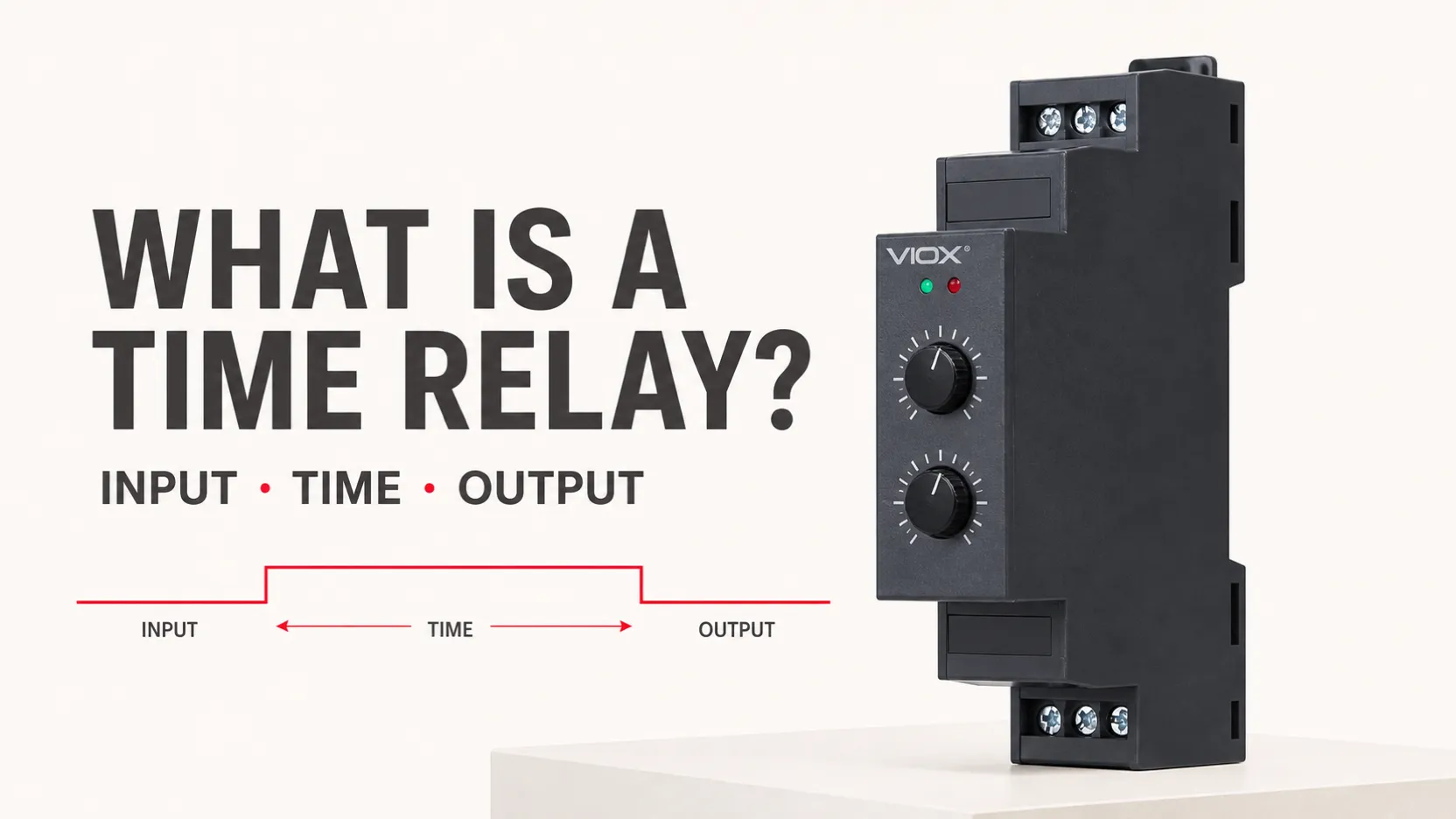
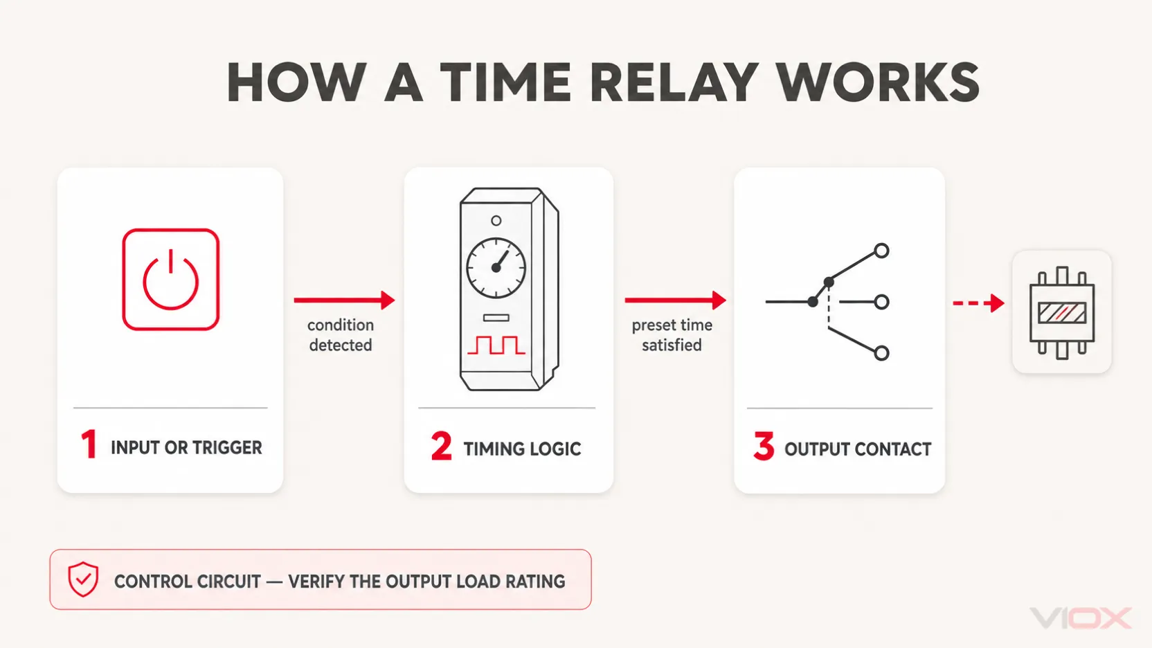
A time relay sits between a control signal and another control-circuit device. Its operation can be understood as three blocks:
- Input or trigger: Supply voltage or a separate control signal starts, stops, or resets the timing sequence.
- Timing logic: An electronic circuit measures the selected interval and applies the configured timing rule.
- Output contact: A normally open, normally closed, or changeover contact switches after the timing condition is satisfied.
The output commonly controls a contactor coil, solenoid, signal lamp, or PLC input. The timer relay is therefore part of the control circuit; it should not be assumed to switch a motor or other power load directly. The permitted load depends on the exact output-contact rating and load category in the model datasheet.
Modern timer relays may start timing when supply power is applied, when a separate trigger changes state, or when a signal is removed. The device name alone does not reveal that behavior. The timing diagram supplied for the exact model is the reliable definition of when timing starts, when the output changes, and how the relay resets.
Time Relay vs Standard Relay, Timer Switch, and PLC Timer
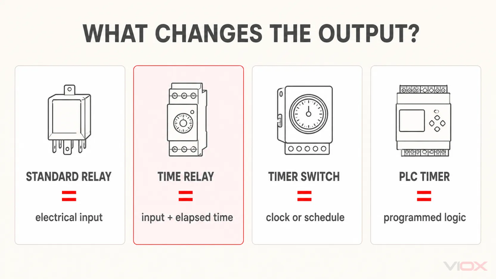
Several devices can create a delayed action, but they do not serve the same control job.
| Device | What causes the output to change? | Typical role | Main boundary |
|---|---|---|---|
| Standard relay | An electrical input changes | Immediate isolation or contact switching | No intentional adjustable timing function |
| Time relay | An input condition plus elapsed time | Simple delayed, interval, or cyclic control | Limited to its published timing functions |
| Timer switch | Clock time, calendar schedule, or countdown | Scheduled lighting and building loads | Usually organized around time of day rather than machine-control signals |
| PLC timer | Software logic and programmed conditions | Multi-input automation, sequencing, alarms, and diagnostics | Requires a PLC, program, and maintained control logic |
A standard relay has a small physical operating time, but that does not make it a time relay. A time relay provides an intentional timing function that the user can select or set. For a deeper device-level comparison, see relay vs timer.
How to Read a Slim DIN-Rail Time Relay
The VIOX-style device supplied for this article is a narrow DIN-rail timer relay with two rotary controls, status indicators, top supply/trigger terminals, and one changeover output contact. That physical layout is common in compact control panels, but the printed diagram and exact datasheet remain the final authority.
| Visible element | Typical role | What you must verify |
|---|---|---|
| A1 / A2 | Control-supply terminals | Rated voltage, AC/DC compatibility, frequency, and DC polarity |
| S | Separate start or control input on some models | Trigger reference, input voltage, pulse requirement, and reset behavior |
| 11 / 12 / 14 | One changeover contact: commonly 11 common, 12 normally closed, and 14 normally open | The contact diagram, load category, voltage, current, and whether an interposing device is required |
| Rotary controls | Usually select a time range, fine time setting, or operating function | The scale multiplier and function code for the exact model |
| Status LEDs | Indicate supply, timing, or output state | The LED legend printed on the device or datasheet |
These markings describe separate parts of the device. The voltage applied to A1/A2 is not the same specification as the voltage or current that the 11/12/14 output contact may switch. Likewise, terminal S should never be treated as a universal trigger terminal without checking the model diagram.
For exact terminal diagrams and common socket formats, use the dedicated time delay relay wiring guide.
A Simple On-Delay Example
An on-delay sequence provides the clearest example of the definition:
Input turns ON → timing begins → preset time expires → output contact changes state
Input turns OFF → timer and output reset, subject to the model's timing diagram
Suppose a control circuit should energize a contactor coil only after a short stabilization period. When the start condition appears, the time relay begins measuring the delay. If the input remains valid until the set time expires, the output contact changes state and the contactor coil can energize.
Other timing functions respond differently. An off-delay function, for example, concerns what happens after a control signal is removed. Those functions belong to the dedicated guide to types of time delay relays.
What a Time Relay Definition Does Not Tell You
Knowing that a device is a time relay is only the first step. The term does not specify:
- the timing function;
- whether timing starts from supply power or a separate trigger;
- the adjustable time range;
- the control-supply voltage;
- the output-contact arrangement and switching duty;
- reset and power-loss behavior;
- mounting format or environmental limits;
- applicable approvals for a particular market or assembly.
IEC 61812-1:2023 covers requirements and tests for time relays and coupling relays within its stated industrial and residential-use scope, but an article-level reference to the standard does not prove that a particular product is certified. For standards interpretation, see the VIOX IEC 61812-1 time relay guide. Always verify an exact model through its datasheet and approval documents.
When you are ready to specify a device, move from the definition to the timer relay selection guide or compare the available VIOX DIN-rail timer relay family.
Time Relay Terminology FAQ
Is a time relay the same as a timer relay?
Usually, yes. In industrial control usage, time relay, timer relay, and time delay relay commonly refer to the same device family. A manufacturer may use one term for the category and another for a particular series or timing function.
What is the main difference between a time relay and a normal relay?
A normal relay changes contact state in response to its input without an intentional adjustable delay. A time relay inserts a defined timing rule between the input condition and the output-contact action.
Is a time relay the same as a timer switch?
Not generally. A time relay usually responds to control-circuit inputs and timing functions. A timer switch is usually organized around clock schedules, calendar programs, or countdown switching.
Does a time relay supply power to the load?
The timer’s output contact switches an external circuit within its published rating. In industrial panels it often controls another device, such as a contactor coil, rather than switching the main power load directly.
What do A1, A2, 11, 12, and 14 mean?
On many industrial relays, A1/A2 identify the control supply and 11/12/14 identify one changeover output contact. The common interpretation is 11 common, 12 normally closed, and 14 normally open, but the printed diagram for the exact relay must be checked before wiring.