
Direct Answer
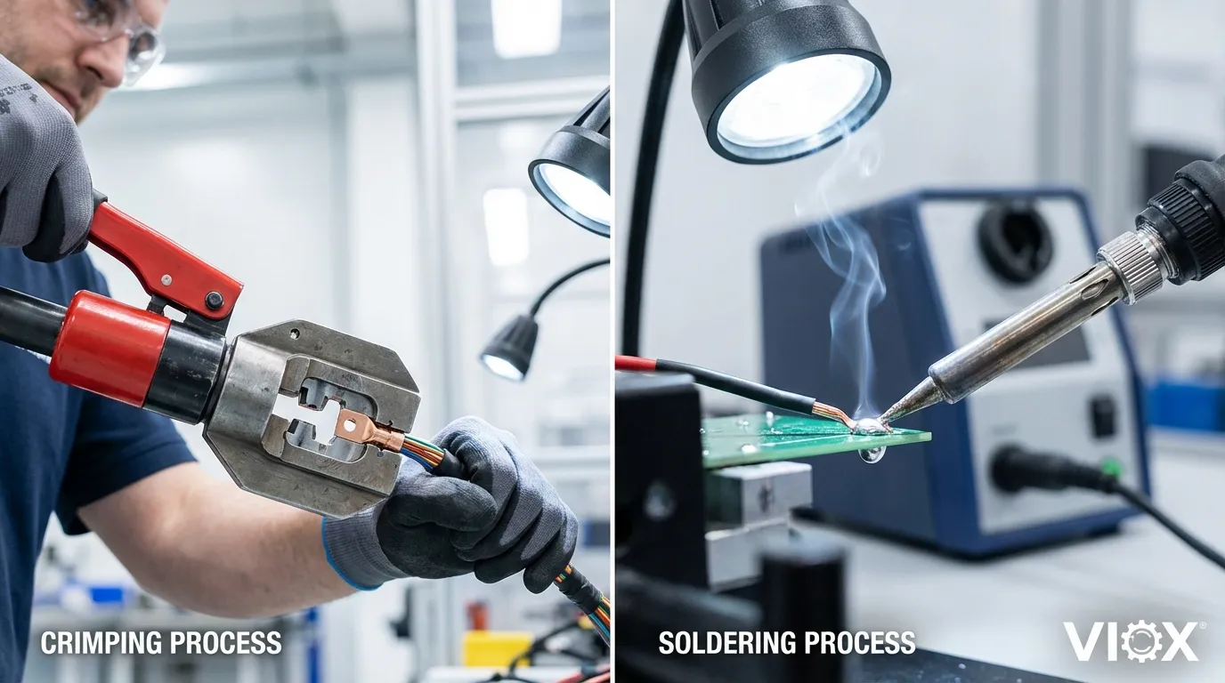
Crimping delivers superior reliability over soldering in high-vibration, thermal cycling, and harsh-environment applications. While soldering creates a metallurgical bond through heat fusion, crimping establishes a gas-tight cold weld through mechanical compression—eliminating heat-affected zones, preventing solder embrittlement, and maintaining wire flexibility at stress points. Industry standards including SAE/USCAR-21, IEC 60352-2, and IPC/WHMA-A-620 mandate crimped connections for automotive and aerospace applications where a 15-year service life under extreme conditions is non-negotiable.
Key Takeaways
Understanding the fundamental differences between crimping and soldering is critical for electrical system reliability. Crimped connections provide mechanical strength through controlled plastic deformation, creating air-tight seals that resist moisture ingress and oxidation. The absence of heat eliminates thermal stress on wire insulation and prevents the formation of brittle intermetallic compounds. In contrast, soldered joints introduce a rigid transition zone where flexible wire meets solidified solder—a notorious failure point under vibration. Modern automotive and industrial standards have largely abandoned soldering in favor of crimping for production harnesses, recognizing that proper crimped terminals consistently outperform solder joints in pull-force testing, thermal shock resistance, and long-term durability.
Why Connection Method Matters: The Hidden Cost of Failure
Connection reliability directly determines system-level performance in electrical assemblies. When a wire harness serves as the energy and signal transmission pathway, any connection weakness propagates into catastrophic system failure. The choice between crimping and soldering isn’t merely a manufacturing preference—it’s an engineering decision with measurable consequences for product lifespan, warranty costs, and safety compliance.
Soldering has dominated electronics assembly for decades, particularly in circuit board applications where components remain stationary. However, the same thermal bonding process that works well for PCB traces becomes a liability in wire-to-terminal connections subjected to mechanical stress. The fundamental problem lies in material science: solder creates a brittle intermetallic zone that cannot accommodate the differential movement between rigid terminals and flexible conductors.
Modern electrical systems demand connections that survive 100,000+ thermal cycles, withstand vibration frequencies exceeding 2000 Hz, and maintain contact resistance below 1 milliohm throughout their service life. These requirements have driven automotive OEMs, aerospace manufacturers, and industrial equipment builders toward crimping as the primary termination method. Understanding why crimping outperforms soldering requires examining the physics of each connection type and their behavior under real-world stress conditions.
Crimping vs. Soldering: Technical Comparison
The mechanical and electrical characteristics of crimped versus soldered connections reveal why industry standards favor crimping for demanding applications. The following comparison examines critical performance parameters that directly impact connection reliability and service life.
| Performance Factor | Crimping (Solderless) | Soldering |
|---|---|---|
| Connection Mechanism | Mechanical compression creating gas-tight cold weld | Metallurgical bonding through thermal fusion |
| Process Temperature | Ambient (no heat applied) | 183-450°C depending on solder alloy |
| Heat-Affected Zone | None—insulation remains intact | Thermal damage risk to wire insulation and adjacent components |
| Vibration Resistance | Excellent—maintains flexibility at stress points | Poor—rigid solder creates stress concentration and fatigue cracks |
| Thermal Cycling Performance | Superior—accommodates differential expansion | Degraded—solder recrystallization and intermetallic growth |
| Contact Resistance | 0.5-1.0 milliohm (stable over time) | Initially low but increases with oxidation and thermal aging |
| Pull-Force Retention | Maintains 90%+ of wire tensile strength | Weakens over time due to solder creep and work hardening |
| Moisture Resistance | Gas-tight seal prevents oxidation | Flux residue attracts moisture; capillary wicking between strands |
| Process Repeatability | Highly consistent with proper tooling and quality control | Variable—depends on operator skill, temperature control, dwell time |
| Inspection Method | Visual examination and dimensional measurement (crimp height/width) | Visual only—internal voids and cold joints invisible |
| Rework Capability | Terminal replacement required | Can be re-soldered (with degradation risk) |
| Automotive/Aerospace Approval | Required by SAE/USCAR-21, AS7928, IEC 60947-4-1 | Prohibited for production harnesses per IPC/WHMA-A-620 |
| Equipment Investment | Moderate—requires calibrated crimping tools and dies | Low—basic soldering iron sufficient for small-scale work |
| Cycle Time (per connection) | 2-5 seconds (manual); <1 second (automated) | 10-30 seconds including heating, cooling, inspection |
| Environmental Impact | No fumes, flux, or lead exposure | Requires fume extraction; lead-free solder alternatives more difficult |
The Physics of Crimped Connections: Why Cold Welding Works
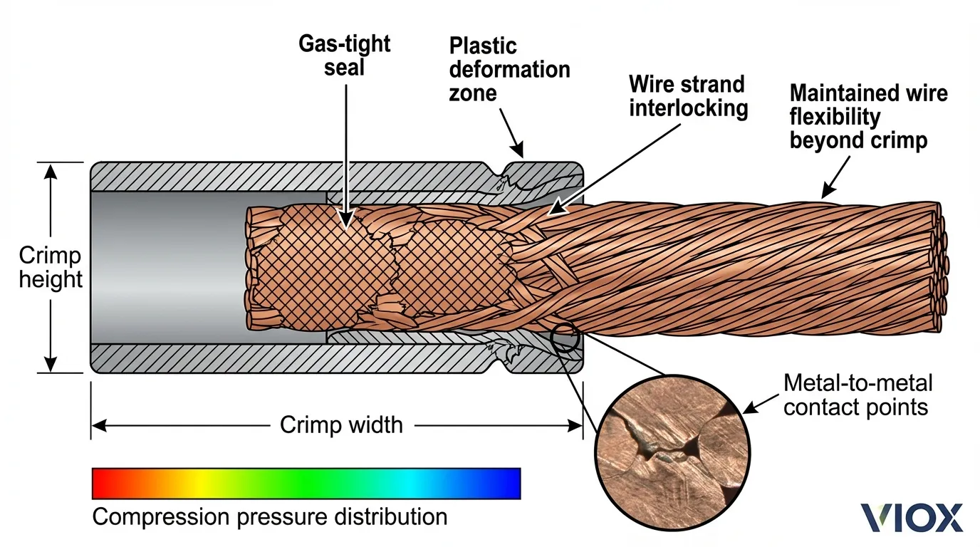
Crimping achieves electrical continuity through controlled plastic deformation rather than thermal bonding. When a crimping die compresses a terminal barrel around a wire conductor, three distinct physical processes occur simultaneously: mechanical interlocking of wire strands within the terminal cavity, elastic deformation of both the terminal material and copper conductors creating spring-back force, and the formation of metal-to-metal contact points where oxide layers fracture under compression pressure.
The resulting connection exhibits characteristics of a cold weld—a solid-state bonding process where sufficient pressure causes atomic-level adhesion between clean metal surfaces. Unlike fusion welding or soldering, cold welding requires no heat input and produces no intermetallic compounds or heat-affected zones. The terminal barrel’s compliance allows the connection to accommodate thermal expansion differentials between the wire and terminal while maintaining constant contact pressure.
Critical to crimping success is achieving the correct compression ratio—the relationship between the terminal barrel’s final compressed height and the wire conductor’s cross-sectional area. Industry standards specify compression ratios between 15-20% for automotive applications, with tighter tolerances required for aerospace and military specifications. Under-crimping results in insufficient contact pressure and high resistance; over-crimping causes wire strand breakage and reduced pull strength. Modern crimping tools incorporate force monitoring and crimp height verification to ensure every connection meets specification.
Why Soldered Connections Fail Under Stress
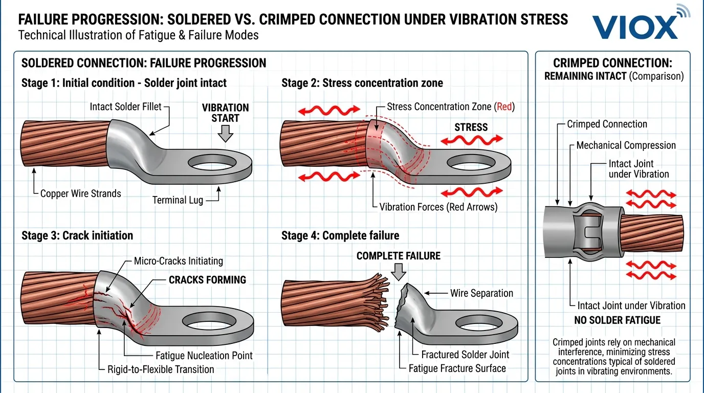
The fundamental weakness of soldered wire connections stems from the material property mismatch between flexible copper conductors and rigid solder alloys. Solder—whether traditional tin-lead (Sn60/Pb40) or modern lead-free compositions (SAC305, Sn96.5/Ag3.0/Cu0.5)—solidifies into a crystalline structure with limited ductility. When a soldered wire experiences vibration or flexing, the stress concentrates precisely at the solder termination point where rigid metal meets flexible stranded wire.
This stress concentration initiates fatigue cracks that propagate through the solder joint with each vibration cycle. Metallurgical analysis of failed solder joints consistently reveals crack initiation at the solder-wire interface, progressing through the solder matrix until complete separation occurs. The failure mode is predictable and well-documented in automotive and aerospace failure analysis reports.
Thermal cycling accelerates solder joint degradation through multiple mechanisms. Differential thermal expansion between copper wire (16.5 ppm/°C), solder alloy (22-25 ppm/°C), and terminal materials creates shear stress at interfaces. Repeated heating and cooling cycles promote solder recrystallization—a metallurgical process where grain boundaries reorganize, increasing brittleness and reducing fatigue resistance. Lead-free solders exhibit particularly poor thermal cycling performance compared to traditional tin-lead alloys, with some SAC alloys showing 50% reduction in fatigue life under accelerated testing.
Additional failure mechanisms include solder wicking—where molten solder flows between wire strands through capillary action, creating a rigid zone extending several millimeters beyond the intended joint. This wicked region eliminates wire flexibility and creates an extended stress concentration zone. Flux residue, if not properly cleaned, attracts moisture and promotes electrochemical corrosion. In automotive underhood environments where temperature swings from -40°C to +150°C are routine, soldered connections rarely survive beyond 5-7 years before exhibiting increased resistance or intermittent failures.
Industry Standards: Why Regulations Mandate Crimping
Automotive and aerospace industries operate under strict quality standards that explicitly prohibit soldering for production wire harness terminations. The SAE/USCAR-21 specification—developed jointly by major automotive manufacturers including Ford, GM, Stellantis, and international partners—defines performance requirements for crimped electrical terminals in automotive applications. This standard mandates that crimped connections survive 15 years or 150,000 miles of service under conditions including thermal cycling from -40°C to +125°C, vibration testing at multiple frequency bands, and exposure to automotive fluids, salt spray, and humidity.
The IPC/WHMA-A-620 standard, which governs cable and wire harness assembly requirements, explicitly states in Section 9.3 that “soldering of crimp-style terminals is not acceptable” because it masks poor crimps and introduces thermal stress. This prohibition reflects decades of field failure data demonstrating that soldered crimps perform worse than properly executed mechanical crimps alone. The standard requires visual inspection criteria, dimensional verification of crimp height and width, and pull-force testing to validate connection integrity.
Aerospace applications follow even more stringent requirements under AS7928 (formerly MIL-T-7928), which specifies wire and cable crimping for aircraft electrical systems. These specifications recognize that connection failures in flight-critical systems carry catastrophic consequences, making reliability non-negotiable. Crimping tools used in aerospace applications must be calibrated annually, and every crimped connection undergoes documented inspection with traceability to the specific tool, operator, and batch of terminals used.
Crimp Quality Control: The Critical Parameters
Achieving reliable crimped connections requires precise control of three interdependent variables: crimp height, crimp width, and wire compaction ratio. Crimp height—measured at the terminal barrel’s compressed dimension perpendicular to the wire axis—directly determines contact pressure and pull strength. Specifications typically define crimp height tolerances within ±0.05mm for automotive terminals, with tighter tolerances required for smaller wire gauges and critical applications.
Crimp width measurement verifies that the terminal wings have properly folded around the wire without excessive deformation or cracking. Width specifications vary by terminal design but generally require that the crimped barrel maintain structural integrity without splits or fractures that could compromise the gas-tight seal. Visual inspection under magnification (10-30x) reveals surface defects including incomplete compression, terminal cracking, or wire strand protrusion.
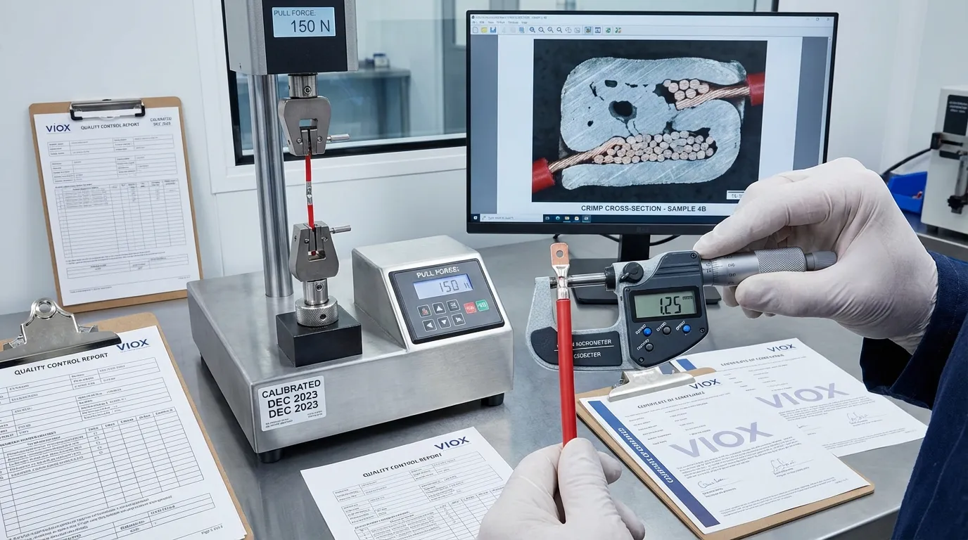
The most critical quality metric is pull-force testing—a destructive test that measures the force required to separate the terminal from the wire. Standards specify minimum pull forces based on wire gauge, with values ranging from 15 Newtons for 24 AWG wire to 400+ Newtons for 10 AWG conductors. Proper crimps typically achieve 90-95% of the wire’s rated tensile strength, meaning the wire itself breaks before the crimp pulls out. Pull testing must be performed at controlled rates (50-250 mm/minute per USCAR-21) to ensure consistent results.
Statistical process control (SPC) methods track crimp quality trends across production runs, identifying tool wear, die misalignment, or operator technique variations before they produce out-of-specification connections. Modern automated crimping systems incorporate in-line force monitoring that measures actual crimping force and flags any connection outside acceptable parameters for immediate rework.
Application Guide: When to Use Each Method
Despite crimping’s advantages for production harnesses and high-reliability applications, soldering remains appropriate for specific use cases. Circuit board assembly, particularly for through-hole components and surface-mount rework, benefits from soldering’s ability to create permanent connections on rigid substrates where vibration stress is minimal. Prototype development and laboratory testing often employ soldered connections for their ease of modification and minimal tooling requirements.
Crimping becomes mandatory in automotive wire harnesses, aerospace electrical systems, industrial control panels, and any application where connections experience vibration, thermal cycling, or harsh environmental exposure. The investment in proper crimping tools—ranging from $200 for manual ratcheting crimpers to $50,000+ for automated crimping machines—pays dividends through reduced warranty claims, improved system reliability, and compliance with industry standards. For related information on selecting appropriate circuit protection for crimped connections, see our guide on circuit breaker selection for industrial panels.
Marine and outdoor applications particularly benefit from crimping’s moisture resistance. The gas-tight seal created by proper compression prevents water ingress and the resulting electrochemical corrosion that rapidly degrades soldered connections in humid or salt-spray environments. When combined with heat-shrink tubing or environmental sealing boots, crimped terminals achieve IP67/IP68 protection levels suitable for submersible applications.
High-current applications (>10 amperes) universally require crimped connections due to superior current-carrying capacity and lower contact resistance. The multiple contact points created by compressed wire strands distribute current flow more effectively than solder joints, reducing localized heating and improving long-term stability. For guidance on proper wire sizing and current capacity calculations, refer to our cable sizing guide.
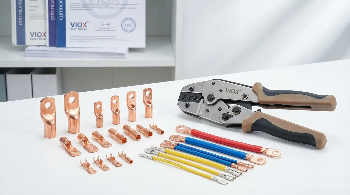
The VIOX Advantage: Precision Crimping Solutions
VIOX Electric specializes in manufacturing high-reliability electrical components designed for demanding industrial, automotive, and renewable energy applications. Our product portfolio includes precision-machined copper terminals, automotive-grade wire harnesses, and custom electrical assemblies that meet or exceed international quality standards including UL, IEC, and automotive OEM specifications.
Our engineering team provides comprehensive support for connection design optimization, including terminal selection, crimping tool specification, and quality control protocol development. We maintain in-house testing capabilities for pull-force validation, thermal cycling, vibration testing, and environmental exposure simulation—ensuring every product delivers documented reliability under real-world operating conditions.
For applications requiring custom terminal designs, non-standard wire gauges, or specialized environmental sealing, VIOX offers rapid prototyping and small-batch production capabilities. Our quality management system maintains full traceability from raw material certification through final inspection, providing the documentation required for aerospace, medical, and safety-critical applications. Learn more about our terminal block solutions and industrial connector options.
Frequently Asked Questions
Q: Can I solder a wire after crimping it for extra strength?
A: No—this practice is explicitly prohibited by IPC/WHMA-A-620 and automotive standards. Soldering after crimping provides no strength benefit because the crimp has already established maximum contact. The added solder actually degrades performance by introducing thermal stress, masking poor crimps during inspection, and creating a brittle zone. If a crimp is properly executed, solder adds nothing; if the crimp is defective, solder conceals the problem until field failure occurs.
Q: How do I know if my crimping tool is producing good connections?
A: Perform regular pull-force testing on sample connections and measure crimp height with a micrometer. Compare results against the terminal manufacturer’s specifications. Visual inspection should reveal complete barrel closure, no wire strand protrusion, no terminal cracking, and proper insulation crimp engagement. If you lack testing equipment, cross-sectional analysis (cutting through the crimp and examining under magnification) reveals internal wire compaction quality. For more on electrical testing procedures, consult our testing guide.
Q: What wire sizes can be crimped versus soldered?
A: Crimping accommodates wire sizes from 30 AWG (0.05mm²) to 4/0 AWG (107mm²) and larger with appropriate terminals and tooling. Soldering becomes increasingly difficult and unreliable above 12 AWG due to heat dissipation challenges and the large rigid zone created. For high-current applications, crimped connections with mechanical fasteners (bolted lugs) are standard practice.
Q: Are crimped connections suitable for high-vibration environments like automotive or aerospace?
A: Yes—crimped connections are specifically designed for high-vibration applications and are mandated by automotive (USCAR-21) and aerospace (AS7928) standards precisely because they outperform soldered connections under vibration stress. The maintained flexibility at the crimp-to-wire transition prevents the fatigue failures that plague soldered joints. For related information on vibration-resistant circuit protection, see our breaker selection guide.
Q: How long do crimped connections last compared to soldered connections?
A: Properly executed crimped connections in automotive applications are designed for 15+ year service life (per USCAR-21 testing requirements) including exposure to thermal cycling, vibration, humidity, and chemical exposure. Soldered connections in similar environments typically begin showing degradation within 5-7 years. In benign environments (climate-controlled, no vibration), both methods can last decades, though crimping still offers superior long-term contact resistance stability.
Q: What’s the difference between insulated and uninsulated crimp terminals?
A: Insulated terminals include a plastic sleeve that provides strain relief and electrical insulation, suitable for general wiring applications. Uninsulated (bare) terminals offer higher current capacity and are preferred for high-amperage connections or when custom heat-shrink tubing will be applied. The crimp quality requirements are identical; the choice depends on application requirements and whether additional environmental sealing is needed. For terminal selection guidance, review our terminal block comparison guide.
Conclusion: Engineering Reliability Through Proper Connection Design
The debate between crimping and soldering ultimately resolves to application requirements and performance priorities. For production wire harnesses, automotive systems, aerospace applications, and any environment involving vibration, thermal cycling, or harsh exposure, crimping delivers demonstrably superior reliability backed by decades of field data and codified in international standards. The initial investment in proper crimping tools and training pays immediate dividends through reduced failure rates, simplified quality control, and compliance with industry requirements.
Soldering retains its place in electronics assembly for circuit board connections and applications where mechanical stress is minimal. However, the notion that soldered wire-to-terminal connections offer superior reliability has been thoroughly disproven by both laboratory testing and field failure analysis. Modern electrical system design recognizes that connection integrity determines overall system reliability—making the choice of termination method a critical engineering decision rather than a matter of personal preference or tradition.
VIOX Electric stands ready to support your connection design requirements with precision-manufactured terminals, custom crimping solutions, and engineering expertise backed by comprehensive testing and quality assurance. Whether you’re designing automotive harnesses, industrial control systems, or renewable energy installations, proper connection technology ensures your products deliver the reliability your customers demand. Contact our engineering team to discuss your specific application requirements and discover how VIOX crimping solutions can eliminate connection-related failures in your electrical systems.
For additional technical resources on electrical system design and component selection, explore our comprehensive guides on circuit protection, wire sizing calculations, and industrial panel design.
