
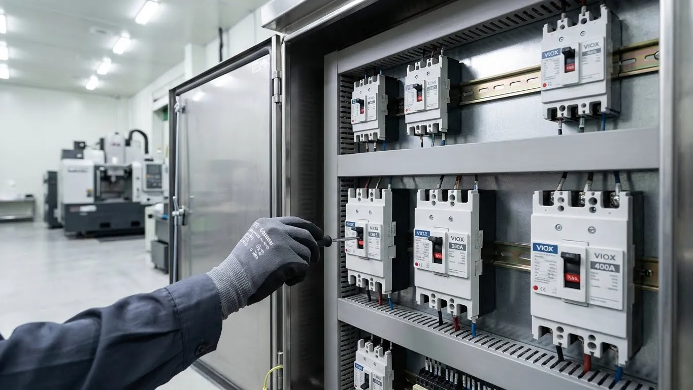
Selecting the right Molded Case Circuit Breaker (MCCB) is a critical engineering decision that directly impacts the safety, reliability, and compliance of your electrical distribution system. Unlike standard residential breakers, MCCBs are designed for high-power industrial and commercial applications, offering adjustable protection settings and high breaking capacities in accordance with IEC 60947-2.
An incorrectly selected MCCB can lead to nuisance tripping, equipment damage, or catastrophic failure during a short circuit. This ultimate guide will walk you through the technical selection process, from calculating fault currents to verifying selectivity, ensuring you choose the perfect MCCB for your panel.
What is an MCCB and Why Use It?
A Molded Case Circuit Breaker (MCCB) is an industrial-grade electrical protection device that protects circuits from overloads and short circuits. It is defined by its molded insulating housing, which contains the switching mechanism, arc extinguishing chamber, and trip unit.
While Miniature Circuit Breakers (MCBs) are suitable for final distribution circuits, MCCBs are the standard for power distribution feeders due to their higher current ratings and adjustable characteristics.
Comparison: MCCB vs. MCB
| Feature | Miniature Circuit Breaker (MCB) | Molded Case Circuit Breaker (MCCB) |
|---|---|---|
| Rated Current (In) | Typically 0.5A – 125A | Typically 16A – 2500A |
| Breaking Capacity (Icu) | Low (4.5kA – 15kA) | High (16kA – 200kA) |
| Trip Characteristics | Fixed (B, C, D curves) | Adjustable (L, S, I, G settings) |
| Standard | IEC 60898-1 (Household) | IEC 60947-2 (Industrial) |
| Operation | Thermal-Magnetic only | Thermal-Magnetic or Electronic (Microprocessor) |
| Remote Control | Limited accessories | Full range (Shunt trip, UVR, Motor operator) |
Key Factors in MCCB Selection
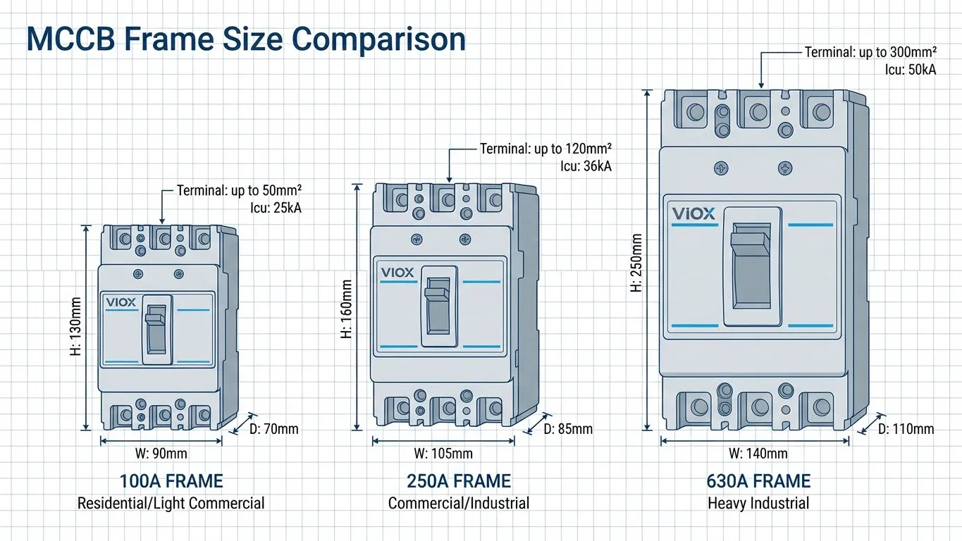
1. Current Rating (In) and Frame Size (Inm)
The Frame Size (Inm) determines the physical dimensions and the maximum current the breaker housing can handle (e.g., 250A frame). The Rated Current (In) is the actual current value the breaker is set to carry (e.g., a 160A trip unit in a 250A frame).
- Selection Rule: $I_b \le I_n \le I_z$
- $I_b$: Design current of the circuit.
- $I_n$: Rated current of the MCCB.
- $I_z$: Current carrying capacity of the cable.
2. Breaking Capacity (Icu vs. Ics)
Breaking capacity is the maximum fault current the MCCB can interrupt safely. Under IEC 60947-2, there are two critical ratings:
- Icu (Ultimate Breaking Capacity): The maximum current the breaker can interrupt once. It may not be usable afterwards.
- Ics (Service Breaking Capacity): The current the breaker can interrupt repeatedly and still remain operational.
For critical applications (hospitals, data centers), ensure Ics = 100% Icu. For standard applications, Ics = 50% or 75% Icu is often acceptable. Learn more about Icu vs Ics ratings.
Breaking Capacity Selection Matrix:
| Application Scenario | Prospective Short Circuit Current (PSCC) | Recommended MCCB Breaking Capacity |
|---|---|---|
| Residential / Light Commercial | < 10 kA | 16 kA or 25 kA |
| Commercial Building Main Panel | 15 kA – 35 kA | 36 kA or 50 kA |
| Industrial Main Switchboard | 35 kA – 65 kA | 70 kA or 85 kA |
| Heavy Industry / Transformer Output | > 70 kA | 100 kA or 150 kA |
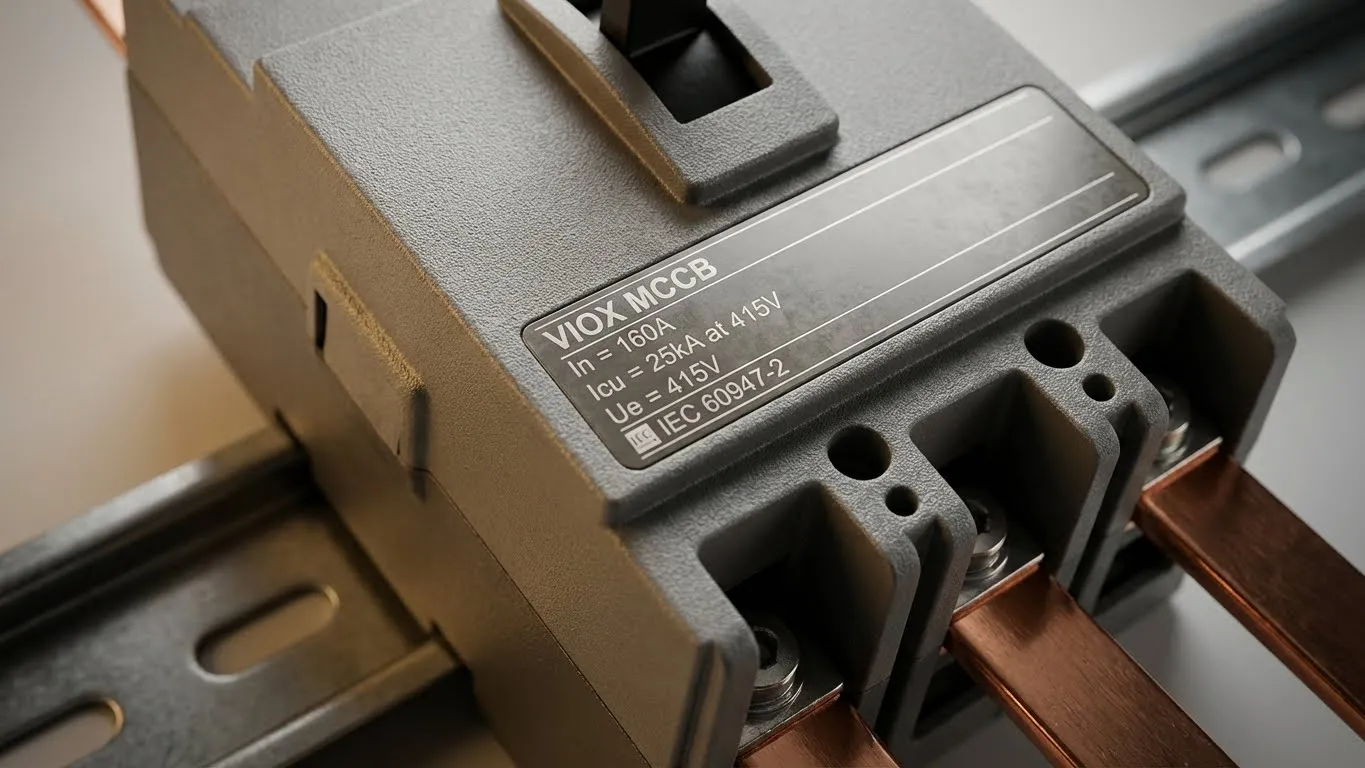
3. Voltage Ratings
Ensure the MCCB meets your system voltage requirements. Refer to our Ue vs Ui vs Uimp guide for deep technical definitions.
- Ue (Rated Operational Voltage): Typically 400V/415V or 690V.
- Ui (Rated Insulation Voltage): Must be $\ge$ Ue (typically 800V or 1000V).
- Uimp (Impulse Withstand Voltage): Resistance to voltage spikes (typically 8kV).
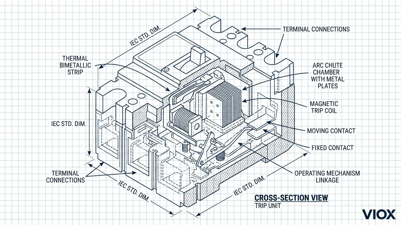
4. Trip Unit Technology
The trip unit is the “brain” of the MCCB.
| Feature | Thermal-Magnetic (TM) | Electronic (Microprocessor) |
|---|---|---|
| Protection Mechanism | Bimetal (Overload) + Coil (Short Circuit) | Current Transformers + CPU |
| Precision | Moderate (affected by ambient temp) | High (temperature independent) |
| Adjustability | Limited (0.7 – 1.0 x In) | Wide range (0.4 – 1.0 x In) + Time delays |
| Functions | LI (Long-time, Instantaneous) | LSI or LSIG (Ground Fault) |
| Cost | Lower | Higher |
| Best For | Standard feeders, simple loads | Generators, complex coordination, motors |
Step-by-Step Selection Guide
Follow this engineering workflow to specify the correct MCCB.
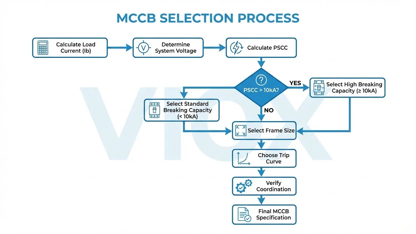
Step 1: Calculate Load Current (Ib)
Determine the full load current of the circuit.
- Formula (3-Phase): $I = P / (\sqrt{3} \times V \times PF)$
- Apply a safety margin (typically 125% for continuous loads per NEC/IEC recommendations).
Step 2: Determine Prospective Short Circuit Current (PSCC)
Calculate the fault current at the point of installation. The MCCB’s Icu must be greater than this value.
- Note: If the PSCC is 45kA, do not select a 36kA breaker. Choose a 50kA or 70kA model.
Step 3: Select Frame Size and Trip Rating
Choose a frame size that accommodates your required current and offers the necessary breaking capacity.
Step 4: Apply Derating Factors
MCCBs are calibrated typically at 40°C. If installed in hotter panels or at high altitudes, you must derate the capacity. See our Electrical Derating Guide.
Temperature Derating Table (Example for Thermal-Magnetic MCCB):
| Ambient Temp (°C) | 30°C | 40°C (Ref) | 50°C | 60°C | 70°C |
|---|---|---|---|---|---|
| Correction Factor | 1.10 | 1.00 | 0.90 | 0.80 | 0.70 |
Step 5: Verify Coordination (Selectivity)
Ensure that a fault downstream trips only the downstream breaker, not the main MCCB.
- Current Selectivity: Upstream MCCB trip threshold > Downstream breaker trip threshold.
- Time Selectivity: Use Electronic Trip Units to add a time delay (Category B breakers) to the upstream MCCB.
- Read more in our Breaker Selectivity & Coordination Guide.
Sizing Example Calculation
Scenario: You need to protect a 3-phase feeder for a sub-panel with a calculated load of 180A. The system voltage is 415V AC. The calculated short-circuit current at the busbar is 32kA. The panel internal temperature is expected to be 50°C.
- Load Requirement: $I_b = 180A$.
- Derating Check: At 50°C, the derating factor is 0.9.
- Required Nominal Rating = $180A / 0.9 = 200A$.
- Frame Selection: Select a 250A Frame MCCB (next standard size up from 200A).
- Trip Unit Setting: Choose a 250A trip unit or an adjustable 250A electronic trip unit set to 0.8 x In ($250 \times 0.8 = 200A$).
- Breaking Capacity: $PSCC = 32kA$.
- Select an MCCB with Icu = 36kA or 50kA (Standard 25kA is insufficient).
- Final Selection: VIOX VMM3-250H (High breaking capacity), 3-Pole, 250A, Electronic Trip Unit.
Common Troubleshooting & Mistakes
- Nuisance Tripping: Often caused by setting the magnetic trip (Im) too low for motor inrush currents. Switch to a generic motor protection curve or adjust the Instantaneous setting.
- Overheating: Check terminal torque. Loose connections are the #1 cause of MCCB failure.
- Breaker Won’t Reset: The mechanism might be in the “Trip” position (center). You must force the handle firmly to “OFF” (reset) before switching to “ON”.
- Buzzing Sound: A slight hum is normal for large currents, but loud buzzing may indicate loose laminations or contacts. See our Diagnostic Guide for Buzzing Breakers.
FAQ
Q: Can I use an AC MCCB for DC applications?
A: Generally, no. DC arcs are harder to extinguish. You must use an MCCB specifically rated for DC or verify the manufacturer’s DC rating for that model. See DC vs AC Circuit Breakers.
Q: What is the difference between 3P and 4P MCCBs?
A: 3P protects the three phases (L1, L2, L3). 4P includes protection for the Neutral conductor, which is essential if the neutral is distributed and high harmonic currents are expected.
Q: How do I test an MCCB?
A: The “Test” button only checks the mechanical trip mechanism. To verify the electronic/thermal accuracy, you need secondary injection testing. Read How to Really Test an MCCB.
Q: Should I use an MCCB or an ICCB?
A: ICCBs (Insulated Case Circuit Breakers) are typically used for higher currents (up to 4000A) and offer higher short-time withstand ratings (Icw) than standard MCCBs. See our MCCB vs ICCB Guide.
Q: How often should MCCBs be maintained?
A: While MCCBs are “maintenance-free” compared to ACBs, they should be visually inspected annually, and thermographic scans should be performed to detect loose connections.
Key Takeaways
- Safety First: Always select an MCCB with an Icu rating higher than the potential fault current (PSCC) at the installation point.
- Future Proofing: Choose adjustable electronic trip units for critical panels to allow for future load changes and better coordination.
- Environment Matters: Don’t ignore temperature and altitude derating factors, or your breaker may trip prematurely.
- Coordination: Ensure your main MCCB delays tripping long enough for downstream MCBs to clear minor faults (Selectivity).
Selecting the right MCCB is a balance of safety, functionality, and cost. By following this guide and adhering to IEC 60947-2 standards, you ensure a robust electrical infrastructure that protects both personnel and equipment.
