On this page
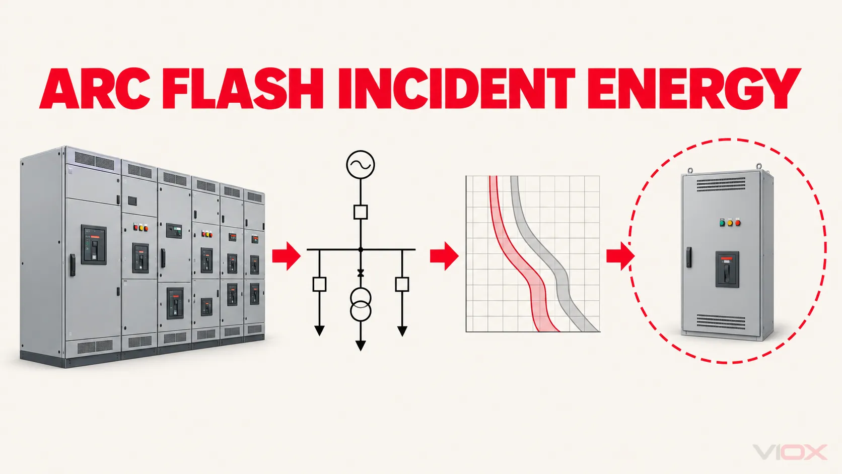
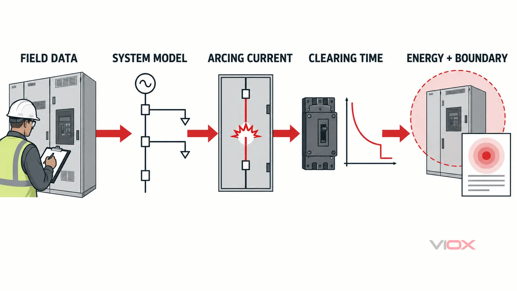
For equipment within its scope, an arc-flash incident energy calculation is not a single fault-current formula. It is a system study that combines a validated power-system model with equipment-specific inputs, calculates arcing current, finds the protective device’s clearing time at that current, and determines predicted incident energy at a defined working distance and the corresponding arc-flash boundary.
IEEE 1584-2018 provides the mathematical models for covered three-phase AC systems. The applicable adopted edition of NFPA 70E uses study results within an electrical safety program, risk assessment, work practices, and personal protective equipment decisions. Neither the calculation result nor an equipment label authorizes energized work.
Safety boundary: Arc-flash studies should be performed or reviewed by qualified people using verified system data and validated software. This article explains the workflow and review logic; it does not reproduce the IEEE equations or replace an engineering study.
The Calculation Is a Dependency Chain
The most useful way to understand an arc-flash study is as a chain of dependent decisions:
Field data → system model → bolted fault current → arcing current → protective-device clearing time → incident energy and arc-flash boundary
An error near the beginning propagates through every later step. A wrong transformer impedance, an assumed conductor length, an obsolete breaker setting, or an incorrect enclosure configuration can change the calculated output even when the software performs the equations correctly.
The result is therefore only as defensible as the input data, system configuration, protection model, and engineering assumptions behind it.
IEEE 1584, NFPA 70E, and the NEC Have Different Jobs
These documents are related, but they are not interchangeable.
| Document or framework | Primary job in this workflow | What it does not replace |
|---|---|---|
| IEEE 1584-2018 plus errata | Provides models and analytical processes for predicted incident energy and arc-flash boundary within its scope | A short-circuit study, coordination study, workplace risk assessment, or PPE program |
| IEEE 1584.1-2022 | Helps an owner specify the scope and deliverables of an arc-flash hazard calculation study | The calculation model itself |
| IEEE 1584.2-2025 | Provides data-collection guidance and checklists for covered three-phase 50/60 Hz systems at 1000 V and below | Data collection for every voltage, system type, or method outside its stated focus |
| NFPA 70E | Governs workplace electrical safety practices in its applicable context, including how incident-energy results are used in risk assessment and PPE decisions | The IEEE 1584 calculation model or permission to perform energized work |
| NEC requirements | Address installation and field-marking requirements in the applicable jurisdiction | A complete workplace risk assessment or incident-energy study |
IEEE identifies IEEE 1584-2018 as an active standard that superseded IEEE 1584-2002. Its public scope describes three-phase AC equipment and conductors from nominal 208 V through 15 kV and expressly excludes single-phase AC calculations, DC calculations, short-circuit studies, overcurrent protective-device coordination studies, and PPE recommendations. The same IEEE page also identifies the available errata, which should be included in the method implementation.
For a detailed separation between generic and incident-energy-based equipment markings, see the VIOX guide to arc-flash label requirements.
What Inputs Does an Arc-Flash Calculation Need?
The calculation inputs describe both the electrical source and the physical arc environment. They must correspond to the equipment and operating condition being studied.
| Input | What it represents | Why it matters | Review question |
|---|---|---|---|
| Nominal system voltage | Voltage at the studied bus or equipment | Selects the applicable model range and affects arcing-current behavior | Does the model voltage match the one-line diagram and field equipment? |
| Bolted fault current | Prospective current for a zero-impedance fault at the location | Establishes the source available to sustain the arc and is an input to arcing-current calculation | Is it derived from a current short-circuit model, not a panel label or guess? |
| Arcing current | Predicted current flowing through the arc | Determines both energy release and where the protective device operates on its time-current response | Were all method-required arcing-current cases evaluated? |
| Electrode configuration | Orientation and arrangement of conductors or electrodes at the possible arc location | Changes how energy may be directed out of or within the enclosure | Is the selected configuration supported by the actual equipment geometry? |
| Conductor gap | Spacing between relevant energized parts | Influences arc behavior and must represent the equipment class or measured geometry | Is the value measured, documented, or assigned using a justified method? |
| Enclosure dimensions | Height, width, and depth of the relevant enclosure | An enclosure can redirect and concentrate thermal energy | Do the dimensions describe the actual arc enclosure rather than the whole room or lineup? |
| Working distance | Distance from the prospective arc source to the worker’s face and torso for the task | Incident energy changes with distance | Is the distance based on the equipment and task, not copied across every bus? |
| Protective-device characteristics | Fuse data, breaker trip curve, relay curve, settings, and operating mechanism | Converts arcing current into fault-clearing time | Does the model use the installed device, settings, and total clearing time? |
| System operating mode | Utility sources, generators, transformers, ties, and switching state in service | Changes fault current and which device clears the fault | Were credible normal and alternate configurations modeled? |
OSHA guidance likewise emphasizes that incident energy depends strongly on current, clearing time, and worker distance. Its guidance also requires reasonable assumptions that resemble the actual exposure, including equipment enclosure and working distance where relevant.
Bolted fault current is not arcing current
Bolted fault current is the current predicted for a fault with negligible impedance. An arc has impedance, so the arcing current used to evaluate protective-device operation is different. A panel’s short-circuit current rating, breaker interrupting rating, or a simplified point-to-point fault-current estimate cannot be substituted for the complete study input.
The VIOX short-circuit current calculation guide explains basic fault-current concepts and breaker kA implications. Those calculations are useful for understanding available current, but they do not provide the physical configuration and protection-response inputs needed for an IEEE 1584 study.
Clearing time must be evaluated at the arcing current
The protective device responds to the current that actually passes through it. After the arcing current is calculated, the engineer determines the corresponding operating time from the installed fuse characteristic, breaker trip curve, or relay-plus-breaker model.
Total clearing time may include sensing, intentional delay, mechanical opening, and interruption. The relevant data and settings must reflect the equipment in service. A generic breaker family curve or an obsolete relay setting can place the calculated current in the wrong operating region.
If you need the underlying reading method, see how to read circuit-breaker time-current curves.
Arc-Flash Study Workflow
1. Define the study scope and deliverables
Identify the facilities, buses, equipment classes, system voltage range, operating configurations, exclusions, field-label expectations, report format, and data assumptions. IEEE 1584.1-2022 addresses recommended requirements for specifying a study’s scope and deliverables.
A useful scope also defines how missing data will be handled, who approves assumptions, which version of the calculation method and errata will be used, and how the final model will be retained.
2. Collect and validate field data
Start with current single-line diagrams, then verify the equipment in the field. Typical records include:
- utility source and transformer information;
- conductor material, size, length, and routing;
- generators, motors, and other relevant sources;
- switchgear, switchboards, motor control centers, panels, and enclosures;
- fuses, breakers, relays, current transformers, and protective settings;
- equipment dimensions, conductor gaps, and electrode arrangement where required;
- normal and alternate switching configurations;
- maintenance switches or energy-reducing settings that may be used under defined conditions.
IEEE 1584.2-2025 adds focused guidance and checklists for data collection on three-phase 50/60 Hz AC systems operating at 1000 V and below. Its existence highlights an important point: accurate field data is a formal study activity, not clerical preparation.
Unverified placeholders should remain visible in the model and report. They should not silently become “as-built” facts.
3. Build and validate the power-system model
The model should reproduce the system’s sources, transformers, conductors, switching devices, loads that materially contribute to fault current, and protection functions. Device identifiers should match the single-line diagram and field labels so that results can be traced back to physical equipment.
Basic validation includes checking voltage bases, transformer connections and impedance, conductor units, source configurations, protective-device identifiers, and whether open or closed ties match each studied scenario.
4. Perform the short-circuit analysis
Calculate available bolted fault current at each relevant location for each credible operating mode. The short-circuit study and the incident-energy study are connected, but they are not the same analysis.
The short-circuit results should also be checked against equipment interrupting ratings and assembly ratings. That equipment suitability question is distinct from predicted thermal exposure to a worker; VIOX explains the distinction in its guide to short-circuit current rating (SCCR).
5. Calculate arcing current for the equipment configuration
Apply the IEEE 1584 model using the correct voltage and physical configuration inputs. Do not import an old IEEE 1584-2002 spreadsheet or equations from a legacy article and assume they represent the 2018 method.
The model implementation should identify the standard edition, incorporated errata, software version, and relevant assumptions. The engineer should also confirm that the equipment lies within the method’s scope before accepting the output.
6. Determine protective-device clearing time
Evaluate the protection system at the calculated arcing current. A small shift in current can cross a pickup threshold or move the operating point from an instantaneous region into a short-time or inverse-time region. That change in clearing time may dominate the incident-energy result.
For relayed breakers, review the complete protection chain rather than the relay curve alone. For fuses, use the applicable total-clearing information. For low-voltage breakers, confirm both the trip-unit settings and the breaker operating characteristics represented in the model.
7. Calculate incident energy and arc-flash boundary
The principal outputs are:
- incident energy at the specified working distance, normally reported in calories per square centimeter in US practice; and
- arc-flash boundary, the distance associated with the threshold defined by the applicable workplace-safety framework.
These outputs must be tied to a scenario, working distance, protection state, and calculation method. A number without those dependencies is difficult to audit or safely apply.
8. Compare valid operating and sensitivity scenarios
Do not automatically choose the scenario with the highest bolted fault current. Compare all credible modeled conditions and retain the governing valid result for the equipment and task context.
The final report should explain which scenario controls, why it controls, and whether the result depends on a maintenance switch or other temporary operating condition.
9. Review, document, and implement the results
The technical review should check input traceability, model warnings, protection curves, scenario logic, scope exclusions, and outliers. The deliverables should preserve enough information for another qualified reviewer to understand how the result was produced.
Only after review should the study results flow into field labels, the electrical safety program, work planning, PPE selection, and mitigation decisions under the applicable requirements.
Why Lower Fault Current Can Mean Higher Incident Energy
The common assumption “more fault current always means more arc-flash energy” is incomplete. Current affects the energy released, but it also controls how quickly the protective device operates.
Consider two credible configurations at the same equipment:
| Scenario | Fault-current condition | Protection response | Possible result |
|---|---|---|---|
| Strong source | Higher arcing current | Instantaneous or fast protection region | High power, short arc duration |
| Weak source or alternate configuration | Lower arcing current | Delayed or inverse-time protection region | Lower power, but much longer arc duration |
If the current in the second scenario falls below an instantaneous pickup or into a slower curve region, the longer duration can produce a higher incident-energy result. The governing case is determined by the complete current-and-time interaction, not by maximum current alone.
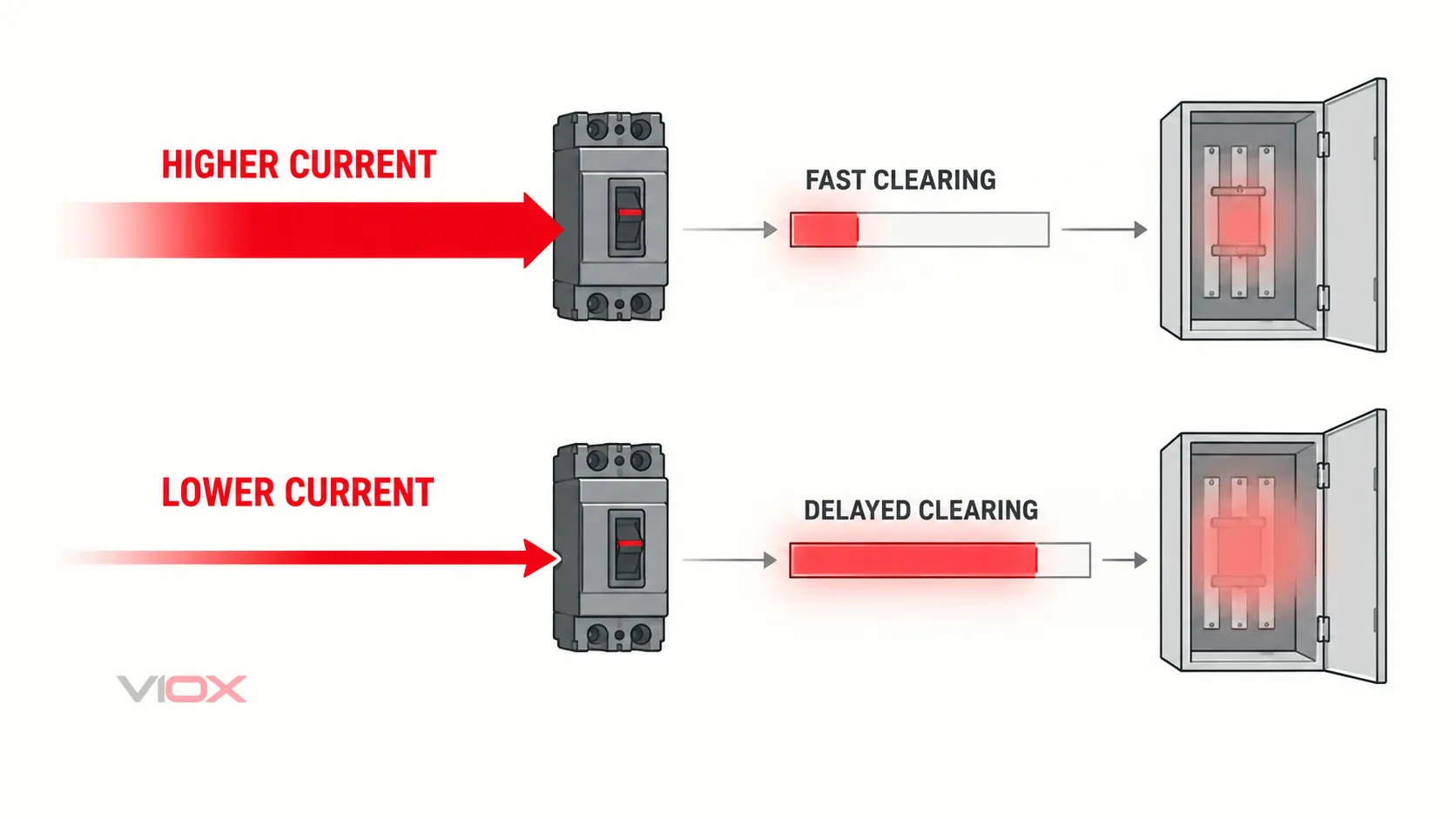
This is also why a sensitivity case required by the selected method must be carried through the protective-device model. It is not enough to reduce the current mathematically while leaving the original clearing time unchanged.
Which Operating Scenarios Should Be Considered?
The scenario set should represent credible system states, not every theoretical switch combination. Depending on the facility, material cases may include:
| System change | Why it can change the result |
|---|---|
| Maximum versus minimum utility contribution | Changes both bolted fault current and protection operating point |
| Bus tie open versus closed | Changes source paths, current magnitude, and clearing device |
| One versus multiple transformers in parallel | Changes available fault current and protection response |
| Generator online or offline | Adds or removes current contribution and may alter relay logic |
| Motor contribution present or absent | Can affect early fault current at relevant buses |
| Normal versus alternate feeder | May place a different protective device in the clearing path |
| Normal versus maintenance settings | Changes protection speed, but only when the alternate state is controlled and applicable |
Model combinations should be technically credible and governed by the facility’s operating procedures. A configuration that cannot occur need not inflate the study, while a common emergency or maintenance configuration should not be ignored merely because it is not the normal one-line state.
How to Review an Arc-Flash Study Result
A reviewer does not need to re-create every equation to find many common defects. For each important bus or equipment item, ask:
Input traceability
- Can the voltage, transformer, conductor, source, and protection data be traced to field records or approved assumptions?
- Are assumed values identified rather than presented as measured facts?
- Do device names agree across the model, one-line diagram, report, and proposed label?
Physical configuration
- Does the electrode configuration match the equipment at the likely arc location?
- Do enclosure dimensions and conductor gaps describe the relevant compartment?
- Is the working distance appropriate for the equipment and task represented?
Protection response
- Is clearing time evaluated at each applicable arcing current rather than at bolted fault current?
- Are installed trip-unit or relay settings documented?
- Does the model include the correct fuse curve or breaker/relay combination?
- Are device condition and maintenance treated consistently with the workplace-safety program?
Scenario logic
- Are credible source, tie, generator, and alternate-feeder states included?
- Does the report show which case governs?
- If an energy-reducing maintenance setting controls the result, is its required operating state clearly identified rather than assumed permanent?
Output interpretation
- Is incident energy tied to a stated working distance?
- Is the arc-flash boundary tied to the stated method and scenario?
- Are out-of-scope equipment and calculation methods identified?
- Are mitigation recommendations followed by recalculation rather than assumed improvement?
What the Result Does—and Does Not—Tell You
Incident energy is a predicted thermal exposure
Incident energy describes predicted thermal energy at a specified distance under the modeled conditions. It is not a complete measure of every arc-flash consequence. Pressure, sound, projectiles, molten material, toxic by-products, and shock hazards require separate consideration.
Arc-flash boundary is not a general safe-working distance
The arc-flash boundary addresses a defined thermal exposure threshold under the applicable framework. It does not replace shock approach boundaries, restricted-access rules, equipment operating procedures, or the requirement to establish an electrically safe work condition whenever required.
A label is a summary, not the study
A field label cannot contain the model, assumptions, protection curves, and scenario comparison behind the result. The retained study documentation is the technical record; the label communicates selected information for field use.
SCCR and interrupting rating answer different questions
SCCR addresses an assembly’s ability to withstand or safely handle specified short-circuit conditions, while a breaker’s interrupting rating addresses its ability to interrupt fault current under stated conditions. Neither rating directly states the incident energy to a worker at a given distance.
Limits of IEEE 1584-2018
The IEEE public scope states that IEEE 1584-2018 covers electrical equipment and conductors in three-phase AC systems from nominal 208 V to 15 kV. It does not provide calculation models for:
- single-phase AC systems;
- DC systems;
- systems outside its stated voltage range;
- the short-circuit analysis itself;
- overcurrent protective-device coordination; or
- PPE recommendations.
Those exclusions do not mean an arc-flash hazard is absent. They mean another technically valid method, appropriate evidence, and qualified engineering judgment are required. The method used should be named and its scope documented.
OSHA also warns that low voltage does not automatically mean low arc-flash risk. The available current, duration, distance, equipment configuration, and work condition must be evaluated rather than dismissed by nominal voltage alone.
When the Study Should Be Reviewed or Updated
Review is appropriate when changes could alter the source, impedance, protection response, equipment configuration, or working assumptions. Examples include:
- utility or transformer changes;
- generator or large-motor additions;
- conductor or feeder modifications;
- replacement of fuses, breakers, relays, or trip units;
- relay-setting or breaker-setting changes;
- bus-tie or operating-procedure changes;
- addition or removal of energy-reducing controls;
- equipment replacement that changes enclosure or electrode configuration;
- discovery that field data or assumptions were incorrect;
- a required periodic review under the applicable safety program or adopted standard.
A mitigation project is not complete merely because a faster device or setting was proposed. The revised configuration must be modeled, coordination and equipment implications checked, and the incident-energy analysis updated.
Arc-Flash Study Review Checklist
Use this final checklist when writing a study specification or reviewing a deliverable:
- The IEEE 1584 edition, errata, and software version are identified.
- Study scope, exclusions, assumptions, and deliverables are explicit.
- Field data is traceable and unverified values are flagged.
- The one-line diagram and calculation model agree.
- Bolted fault current is calculated for credible operating modes.
- Arcing current is calculated using the correct equipment configuration.
- Protective-device clearing time is determined at each applicable arcing current.
- Electrode configuration, conductor gap, enclosure dimensions, and working distance are justified.
- Credible source, tie, generator, and alternate-feeder scenarios are compared.
- The governing scenario is identified for each reported result.
- Incident energy and arc-flash boundary are tied to a working distance and scenario.
- Out-of-scope systems use a named, justified alternative method.
- Study outputs are not presented as permission for energized work.
- Labels, one-line diagrams, reports, and safety-program records use consistent equipment identifiers.
- Any mitigation change is recalculated and reviewed before implementation.
The strongest arc-flash study is not the one with the most conservative-looking number. It is the one whose inputs, assumptions, protective-device response, scenario selection, and limits are transparent enough to be checked and kept current.
Sources
- IEEE 1584-2018: IEEE Guide for Performing Arc-Flash Hazard Calculations
- IEEE 1584.1-2022: Scope and Deliverable Requirements for an Arc-Flash Hazard Calculation Study
- IEEE 1584.2-2025: Arc-Flash Study Data-Collection Guide and Checklists
- OSHA: Electric-Arc Flash Hazards
- OSHA: Protecting Employees from Electric-Arc Flash Hazards
- OSHA 1910.269 Appendix E: Protection From Flames and Electric Arcs