
⚠️ CRITICAL WARNING: Using an AC circuit breaker in a DC application can result in catastrophic equipment failure, electrical fires, and serious safety hazards. The fundamental difference in arc behavior between AC and DC systems makes this substitution extremely dangerous and potentially life-threatening.
A DC circuit breaker is a specialized protective device engineered to automatically interrupt direct current (DC) flow when hazardous conditions such as overcurrent, short circuits, or electrical faults occur. Unlike standard AC breakers, DC circuit breakers incorporate advanced arc suppression technology to safely interrupt continuous current flow—a challenge that makes DC protection fundamentally more complex than AC protection.
These essential safety devices serve as the primary defense in DC electrical systems, protecting solar photovoltaic installations, battery energy storage systems, electric vehicle charging infrastructure, telecommunications equipment, and marine electrical systems.
The Physics Behind DC Circuit Breakers: Why AC Breakers Cannot Protect DC Systems
Understanding the Zero-Crossing Point Challenge
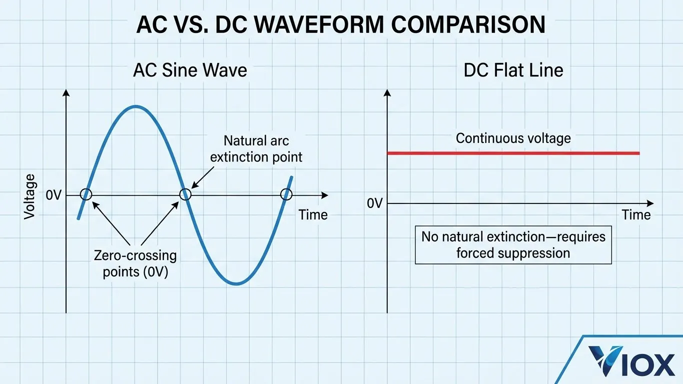
The critical difference between AC and DC circuit protection lies in the zero-crossing point—the moment when alternating current voltage naturally drops to zero volts.
In AC systems, current oscillates through zero voltage 100-120 times per second (depending on 50Hz or 60Hz frequency). This natural zero-crossing creates optimal conditions for arc extinction. When an AC breaker opens its contacts, the arc naturally extinguishes at the next zero-crossing point.
DC systems have no zero-crossing point. Direct current flows continuously at constant voltage, creating a sustained electrical arc that refuses to self-extinguish. This fundamental difference makes DC arc interruption exponentially more challenging and dangerous.
AC vs DC Circuit Breaker: Critical Comparison
| Feature | AC Circuit Breaker (MCB) | DC Circuit Breaker (DC MCB) |
|---|---|---|
| Arc Extinction | Natural at zero-crossing (every 8-10ms) | Requires forced magnetic blowout |
| Zero Crossing | 100-120 times per second | Never occurs |
| Polarity Sensitivity | No polarity requirements | Often polarized (+/- direction matters) |
| Arc Chute Design | Standard grid configuration | Enhanced with magnetic blowout coils |
| Interrupting Capacity | Lower ratings sufficient | Higher ratings required for same current |
| Voltage Rating | Typically 230-400V AC | 12V to 1500V DC |
| Size | Smaller for equivalent rating | 20-30% larger due to arc suppression |
| Cost | Lower | 30-50% higher |
| Failure Mode | Safe trip failure | Fire risk if incorrectly rated |
Engineering Note: Never substitute an AC breaker rated for 250V AC in a DC application, even at lower DC voltages. A 250V AC breaker may fail catastrophically at just 48V DC due to inadequate arc suppression capabilities.
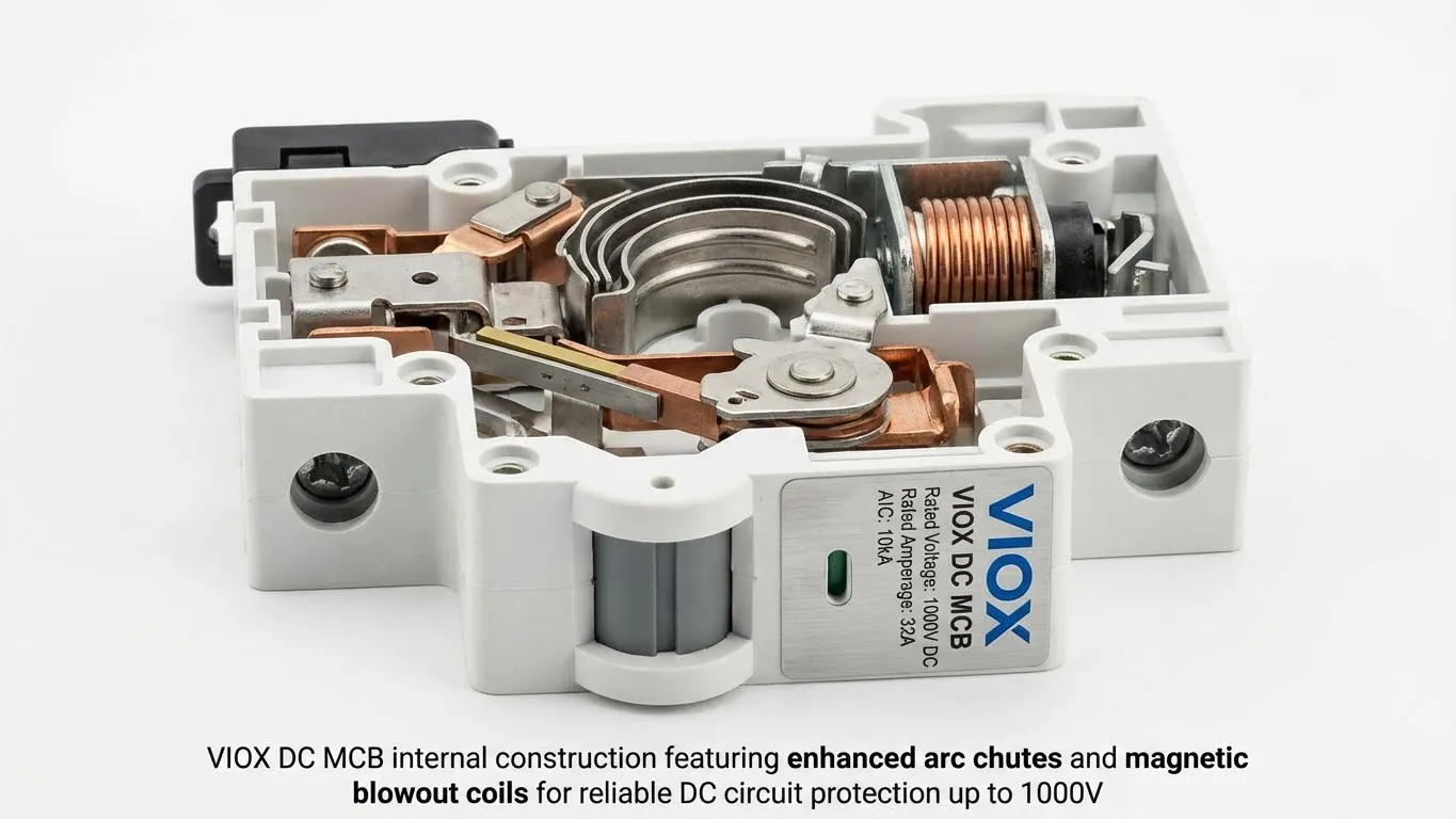
Internal Anatomy: How DC Circuit Breakers Achieve Arc Suppression
Critical Components for DC Protection
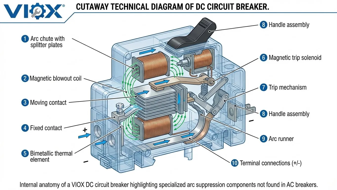
The Arc Chute: The Heart of DC Protection
The arc chute represents the most critical component differentiating DC breakers from AC breakers. This assembly consists of:
- Splitter Plates: Multiple metallic plates arranged in series that divide the arc into smaller segments
- Arc Runners: Copper or steel rails that guide the arc upward into the splitter plates
- Cooling Chamber: Extended containment area that rapidly cools arc gases
Magnetic Blowout Coils: Forcing Arc Extinction
Magnetic blowout coils create powerful magnetic fields that physically push the electrical arc upward into the arc chute. The interaction between the arc’s current and the magnetic field generates a Lorentz force that:
- Stretches the arc length (increasing resistance)
- Drives the arc into splitter plates (dividing and cooling)
- Forces arc gases into cooling chambers
- Achieves arc extinction through energy dissipation
This forced arc suppression replaces the natural zero-crossing mechanism absent in DC systems.
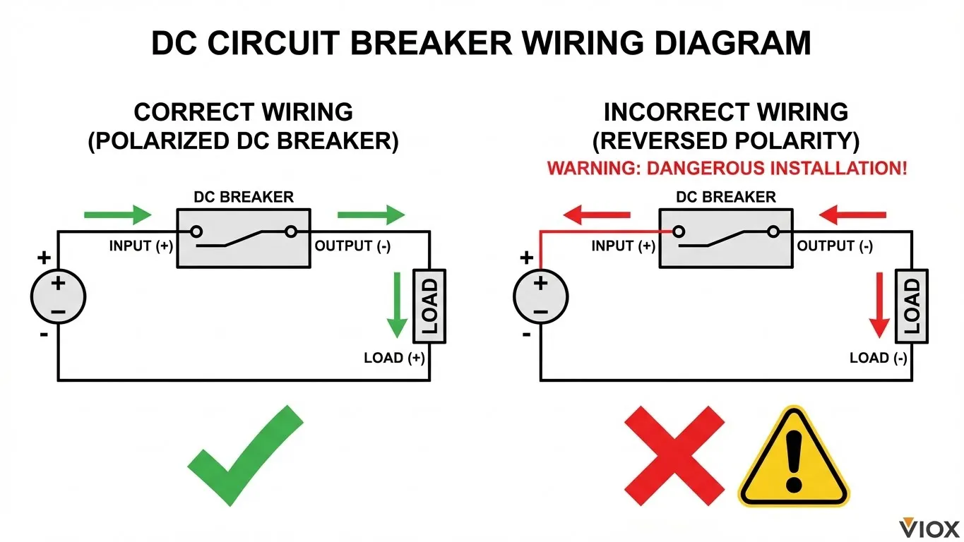
Critical Safety: DC Circuit Breaker Polarity and Wiring
Polarized vs Non-Polarized DC Breakers
Polarized DC breakers must be wired with correct polarity to function safely. The arc suppression mechanism depends on current direction through the magnetic blowout coil.
⚠️ WARNING: Reverse polarity wiring in polarized DC breakers can result in:
- Failed arc suppression
- Contact welding
- Thermal runaway
- Fire hazard
Non-polarized DC breakers (like VIOX advanced series) function correctly regardless of polarity direction, providing enhanced safety and installation flexibility.
Installation Safety Checklist
- Verify breaker DC voltage rating exceeds system maximum voltage
- Confirm correct polarity orientation (check + and – markings)
- Ensure wire gauge meets breaker ampacity requirements
- Verify breaker interrupting capacity exceeds calculated fault current
- Install in well-ventilated location away from flammable materials
- Label circuits clearly for maintenance safety
How to Size Your DC Circuit Breaker: The 1.25x Rule Explained
Unlike AC systems where current naturally oscillates and provides cooling intervals, DC loads—especially in solar photovoltaic and battery energy storage applications—sustain high currents continuously for extended periods. This sustained current flow generates cumulative heat in conductors and breaker contacts, requiring engineers to apply safety factors that prevent nuisance tripping, contact overheating, and premature equipment failure.
Both the National Electrical Code (NEC) and International Electrotechnical Commission (IEC) standards mandate that DC circuit breakers be sized to handle 125% of continuous load current, ensuring reliable operation under sustained high-current conditions.
1. Voltage Rating Selection (Vbreaker)
The breaker’s voltage rating must exceed the maximum system voltage to provide adequate arc suppression capability and dielectric strength.
Engineering Rule:
Vbreaker ≥ Vsystem_max
For optimal safety margin, select breaker voltage rating at least 125% of maximum system voltage:
Example 1: 48V battery system with 58V maximum charge voltage
- Minimum breaker rating: 58V × 1.25 = 72.5V → Select 80V rated breaker
⚠️ Critical Warning: Never substitute a 230V AC breaker in DC applications, even at lower DC voltages. A 250V AC breaker may fail catastrophically at just 48V DC due to inadequate DC arc suppression mechanisms. AC voltage ratings are fundamentally incompatible with DC interruption requirements.
2. Current Rating Calculation (Ibreaker)
According to NEC Article 690.8(B) and IEC 60947-2 standards, circuit breakers protecting continuous loads (operating >3 hours) must be rated at 125% of the continuous load current.
The 1.25x Safety Factor Formula:
Ibreaker = Icontinuous_load × 1.25
This safety factor accounts for:
- Sustained heat generation in DC systems without natural cooling periods
- Ambient temperature variations affecting breaker thermal characteristics
- Conductor resistance increases with temperature
- Manufacturing tolerances in breaker trip characteristics
Practical Example 1 – Solar PV Array:
You have a solar photovoltaic array producing 20 Amps continuously during peak sun hours.
- Calculation: 20A × 1.25 = 25A
- Selection: Choose the next standard size up → 25A or 32A DC circuit breaker
Practical Example 2 – Solar Charge Controller:
- Solar charge controller: 3000W ÷ 48V = 62.5A
- Required breaker rating: 62.5A × 1.25 = 78.125A → Select 80A or 100A breaker
Standard Breaker Current Ratings: When applying the 1.25x rule, round up to the next available standard rating: 6A, 10A, 16A, 20A, 25A, 32A, 40A, 50A, 63A, 80A, 100A, 125A.
3. Interrupting Capacity (AIC Rating)
The interrupting capacity must exceed maximum available fault current. For battery systems with low internal resistance, fault currents can reach dangerous levels that standard breakers cannot safely interrupt.
Fault Current Estimation:
Ifault = Vbattery / Rtotal
Where Rtotal includes battery internal resistance, conductor resistance, and connection resistance.
Example: 48V battery bank with 0.01Ω total resistance
- Fault current: 48V ÷ 0.01Ω = 4,800A
- Required AIC rating: Minimum 6kA, recommended 10kA
AIC Selection Guidelines by Application:
- Residential solar systems (small battery banks): 5kA minimum
- Commercial solar installations: 10kA minimum
- Industrial battery energy storage (large banks): 15-20kA minimum
- Utility-scale applications: 25kA+ required
Undersizing interrupting capacity creates catastrophic failure risk—the breaker may explode or weld closed during fault conditions, eliminating all circuit protection.
DC Circuit Breaker Selection Guide by System Voltage
| System Voltage | Typical Applications | Recommended Breaker Rating | Current Range | AIC Minimum |
|---|---|---|---|---|
| 12V DC | Automotive, RV lighting, marine electronics | 24V or 32V | 5-100A | 5kA |
| 24V DC | Telecommunications, small solar systems | 48V or 60V | 10-125A | 5kA |
| 48V DC | Off-grid solar, data centers, telecom | 80V or 100V | 20-250A | 10kA |
| 120-250V DC | Commercial solar, EV charging | 400V or 500V | 32-400A | 15kA |
| 600-1000V DC | Utility-scale solar, BESS | 1000V or 1500V | 63-630A | 20kA+ |
Types of DC Circuit Breakers
Miniature Circuit Breakers (DC MCB)
- Current Range: 6A to 125A
- Applications: Residential solar, RV systems, telecommunications
- Advantages: Compact, DIN-rail mounting, cost-effective
Molded Case Circuit Breakers (DC MCCB)
- Current Range: 100A to 2500A
- Applications: Commercial solar, industrial battery systems, EV charging
- Features: Adjustable trip settings, higher interrupting capacity
Trip Curve Characteristics
| Trip Curve | Magnetic Trip Range | Best Applications | DC Suitability |
|---|---|---|---|
| Type B | 3-5× rated current | Lighting, residential solar | Good |
| Type C | 5-10× rated current | General commercial, battery systems | Excellent |
| Type D | 10-20× rated current | Motor circuits, high inrush loads | Good |
| Type K/Z | Adjustable | Telecommunications, sensitive equipment | Excellent |
Critical Applications of DC Circuit Breakers
Solar Photovoltaic Systems
DC circuit breakers protect PV arrays, string combiners, and inverter inputs. Key requirements include:
- Voltage ratings up to 1000V or 1500V
- High temperature operation (roof-mounted equipment)
- UV-resistant enclosures
Battery Energy Storage Systems (BESS)
Protection for lithium-ion and lead-acid battery banks requires:
- Bidirectional current handling (charge/discharge)
- High AIC ratings (>10kA) due to low battery impedance
- Thermal monitoring integration
Electric Vehicle Charging Infrastructure
DC fast chargers demand specialized protection:
- Current ratings 125A to 500A
- Rapid response times (<5ms)
- Communication protocols for smart charging
Data Centers and Telecommunications
Mission-critical applications require:
- High reliability (MTBF >100,000 hours)
- Remote monitoring capabilities
- Selective coordination with upstream protection
Frequently Asked Questions About DC Circuit Breakers
Can I use an AC circuit breaker for DC applications?
No, absolutely not. AC circuit breakers lack the specialized arc suppression mechanisms required for DC current interruption. Using an AC breaker in a DC application creates serious fire and equipment damage risks. The absence of zero-crossing points in DC systems means AC breakers cannot reliably extinguish arcs, potentially leading to contact welding and thermal runaway conditions.
What causes a DC circuit breaker to trip?
DC circuit breakers trip due to: (1) Overcurrent conditions where load current exceeds the breaker’s thermal rating for extended periods, (2) Short circuits creating instantaneous high-fault currents that trigger magnetic trip mechanisms, (3) Ground faults in systems with ground-fault protection, and (4) Arc faults in breakers equipped with arc-fault detection. The thermal-magnetic design provides coordinated protection against both sustained overloads and instantaneous faults.
Does polarity direction matter when wiring DC circuit breakers?
Yes, for most DC circuit breakers. Polarized DC breakers must be wired with the positive (+) terminal connected to the power source and negative (-) terminal to the load. Reverse polarity can disable arc suppression mechanisms and create fire hazards. However, advanced VIOX non-polarized DC breakers function correctly regardless of connection direction, eliminating this installation risk and providing greater flexibility.
How do I calculate the correct breaker size for my solar system?
Calculate breaker size using this formula: Breaker Rating = Maximum Current × 1.25. For example, a 5kW solar array at 48V produces 104A (5000W ÷ 48V). Apply the 125% safety factor: 104A × 1.25 = 130A, so select a 150A DC circuit breaker. Always verify the breaker’s voltage rating exceeds system maximum voltage and interrupting capacity exceeds calculated fault current.
What is the difference between AIC and voltage ratings?
Voltage rating indicates the maximum continuous operating voltage the breaker can safely handle (e.g., 1000V DC). AIC (Ampere Interrupting Capacity) specifies the maximum fault current the breaker can safely interrupt without damage (e.g., 10kA). Both ratings are critical: voltage rating must exceed system voltage, while AIC must exceed the maximum available fault current. Undersizing either parameter creates safety hazards.
How often should DC circuit breakers be tested and maintained?
Initial testing: Within 30 days of installation, manually operate the breaker 3-5 times to verify mechanical function. Routine maintenance: Inspect quarterly for signs of overheating (discoloration, melted insulation), verify torque on terminal connections (per manufacturer specifications), and test trip function semi-annually. Replacement criteria: Replace breakers showing contact erosion, case damage, or that have interrupted major fault currents exceeding 80% of their AIC rating. High-reliability applications may require thermal imaging inspection annually.
Conclusion: Selecting the Right DC Circuit Breaker
DC circuit breakers represent the most critical safety component in direct current electrical systems. Understanding the fundamental differences between AC and DC protection—particularly the zero-crossing challenge and arc suppression requirements—enables proper specification and installation.
When selecting DC circuit breakers, prioritize three essential factors:
- Voltage rating must exceed maximum system voltage by 25%
- Current rating should be 125% of continuous load current
- Interrupting capacity must exceed calculated fault current
For solar photovoltaic systems, battery energy storage, EV charging infrastructure, and telecommunications applications, VIOX DC circuit breakers provide proven reliability with advanced features including non-polarized operation, high interrupting capacity up to 20kA, and voltage ratings to 1500V DC.
Never compromise on DC circuit protection—the relatively small investment in quality circuit breakers prevents catastrophic equipment damage, electrical fires, and safety hazards. Contact VIOX Electric’s engineering team for application-specific DC breaker selection and technical support.
About VIOX Electric: As a leading B2B manufacturer of DC circuit protection equipment, VIOX Electric specializes in high-performance DC circuit breakers for renewable energy, industrial, and transportation applications. Our engineering team provides technical support for complex DC protection requirements worldwide.
