On this page
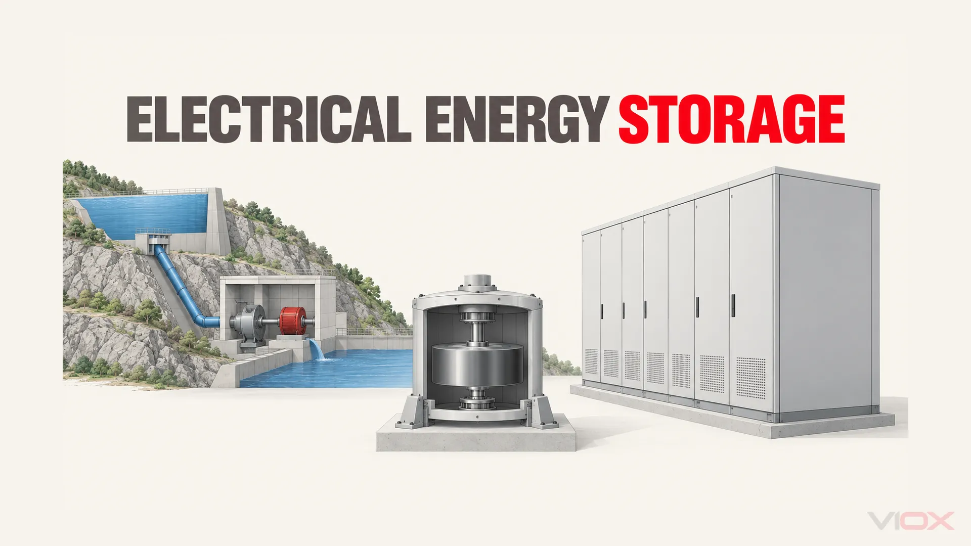
Electrical energy storage systems take energy from an electrical supply, retain it in a storage medium, and deliver electricity later. Batteries are one type. Other technologies store energy in raised water, compressed air, rotating masses, electric or magnetic fields, heat, or manufactured fuels. Their usefulness depends on the required power, duration and operating conditions.
The key distinction is the output: equipment that returns electricity performs a different job from equipment that supplies stored heat or cooling. Both can help manage electrical demand, but they are not interchangeable sources of backup power.
Types of Electrical Energy Storage Systems
Use the table to identify the stored-energy form first, then check the conversion equipment and site constraints. It is a technology map, not a ranking of universally better or worse systems.
| Technology | Where the energy is stored | How electricity is recovered | Useful task and limiting condition |
|---|---|---|---|
| Battery energy storage system (BESS) | Electrochemical reactions in cells or flow-battery electrolytes | Discharge produces direct current (DC); conversion equipment supplies the required output | Building, industrial and grid storage; chemistry, thermal management and usable capacity matter |
| Pumped-storage hydropower | Gravitational potential of elevated water | Water flows through a turbine-generator | Large energy-shifting projects; suitable elevation, reservoirs and permitting are essential |
| Compressed-air energy storage (CAES) | Pressurized air, with thermal management depending on the design | Expanding air drives a generator through suitable machinery | Site-dependent energy storage; some cycles also consume fuel during discharge |
| Flywheel storage | Kinetic energy of a rotating mass | A motor-generator extracts energy as the rotor slows | Rapid power exchanges and cycling; containment, losses and usable speed range constrain capability |
| Capacitors and supercapacitors | Stored charge; supercapacitor behavior depends on electrode technology | Power electronics extract energy as voltage falls | Short, high-power exchanges; energy density and self-discharge limit prolonged delivery |
| Superconducting magnetic energy storage (SMES) | Magnetic field associated with current in a superconducting coil | Conversion equipment transfers energy to the electrical system | Specialized fast-response tasks; cryogenic equipment is part of the system |
| Thermal storage with electrical recovery | Heat in a storage material | A heat engine or other conversion cycle generates electricity | Heat-to-power applications; a tank of hot material alone is not an electrical output system |
| Hydrogen-based electrical storage | Chemical energy of hydrogen produced using electricity | A fuel cell or suitable generator converts the fuel back to electricity | Extended storage where the full conversion chain suits the site; hydrogen production alone does not provide electrical discharge |
This grouping follows the storage forms described by the U.S. Department of Energy (DOE) in its distributed-energy technology overview and the mechanisms reviewed in its Electricity Storage Technology Review. The U.S. Energy Information Administration (EIA) electricity-storage overview explains commercial electricity-return paths and fuel-assisted compressed-air operation. These sources describe technologies, not certification of a particular installation.
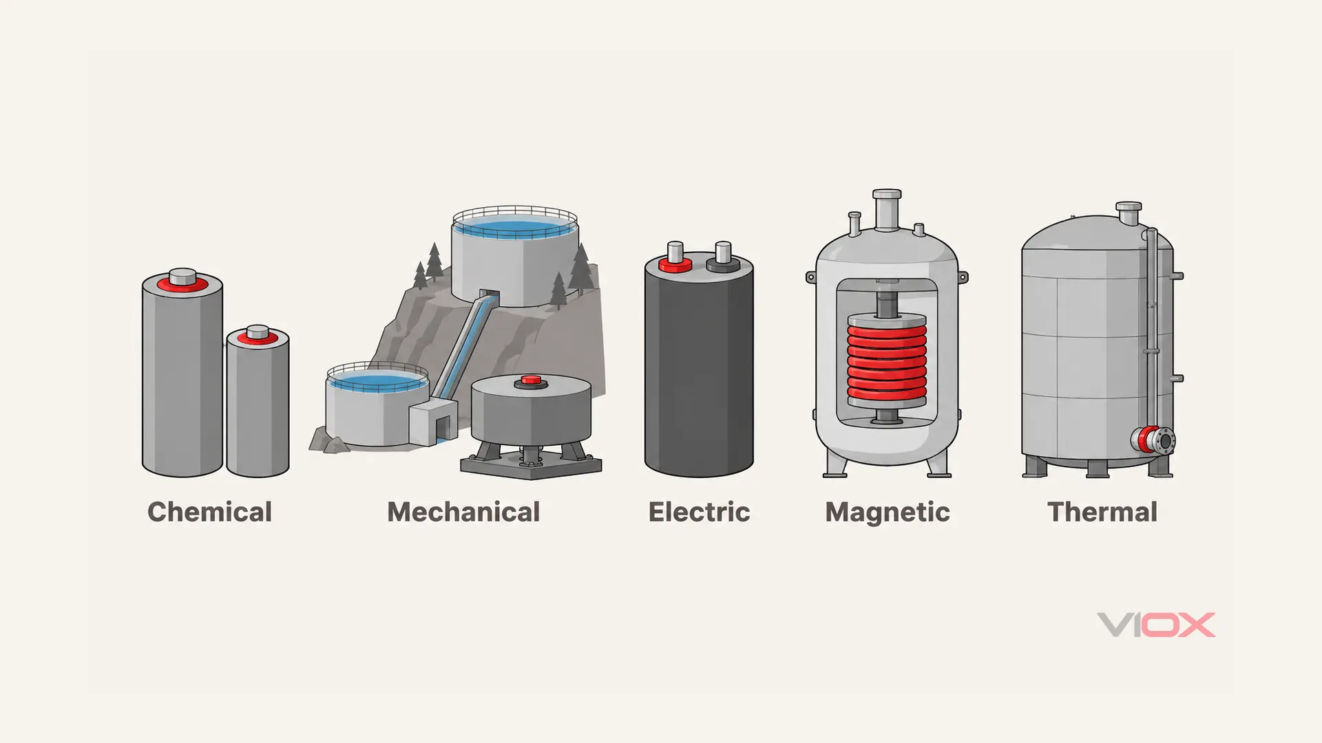
The illustration shows stored-energy forms, not a wiring diagram or relative equipment scale. Thermal storage needs a separate electrical-recovery path when electricity is the required output.
EES, EESS, ESS and BESS: What the Terms Mean
ESS means energy storage system and is a broad umbrella term. EES means electrical energy storage; EESS is also used for electrical energy storage systems. BESS identifies the battery-based subset. A battery system is an ESS, but an ESS does not have to contain batteries.
The International Electrotechnical Commission’s IEC 62933-1:2024 provides vocabulary for grid-connected EES systems that take electricity from a power system, store energy internally and return electricity. Charging and discharging may involve conversion. That scope is narrower than every product casually marketed as an “energy storage system,” including systems whose final output is heat or a fuel sold for another use.
For battery racks, battery management and power conversion in more depth, use the battery energy storage systems guide. The technology map above remains useful when deciding whether the task is battery storage at all.
Is Thermal Storage an Electrical Energy Storage System?
Not automatically. An ice-storage installation can move chiller consumption away from a peak period and supply cooling later. It does not necessarily produce electricity during discharge. Similarly, a hot-water tank can store useful heat without any generator.
Thermal storage can support electricity production when the stored heat feeds a power-conversion cycle. Solar-thermal plants may charge that storage directly from sunlight rather than electricity, so the charging source also matters. DOE’s solar and storage explanation distinguishes direct heating or cooling from thermal storage used to generate electricity.
Ask two questions when reading a specification: What charges the store, and what leaves it during discharge? This prevents an energy-saving measure from being mistaken for a source capable of powering electrical loads.
How an Electrical Storage System Works
There are three functional stages: charge the storage medium, retain the energy, and discharge through the equipment required by the load or grid. Conversion losses and auxiliary consumption mean the recovered electrical energy is not identical to the charging energy.
The physical equipment varies. Pumped hydro uses hydraulic machinery; a flywheel uses a motor-generator; a battery system connected to alternating current (AC) commonly uses bidirectional power conversion. They share the energy-transfer sequence, not an identical cabinet layout.
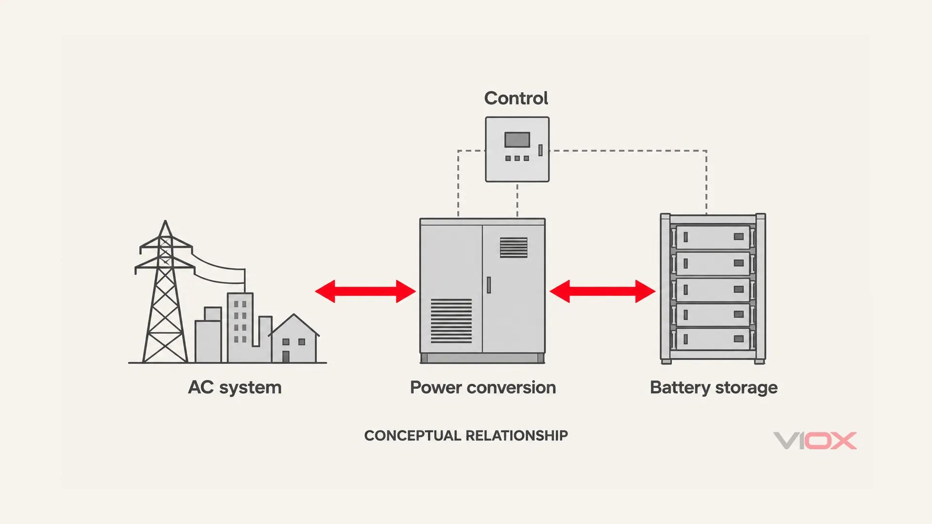
This is an AC-connected battery example, not a universal ESS arrangement. Solid arrows represent functional power exchange; dashed paths represent control. Protection, isolation, earthing and terminal wiring are intentionally omitted and must be designed separately.
Power, Energy and Duration Are Different Ratings
Power, in kilowatts (kW) or megawatts (MW), describes the rate of electrical delivery or absorption. Energy, in kilowatt-hours (kWh) or megawatt-hours (MWh), describes a quantity accumulated over time. A large energy capacity does not establish that the converter can start a large motor, and a high power rating does not establish hours of autonomy.
For a constant load, an initial duration estimate is:
Duration (h) = usable output energy (kWh) / load power (kW)

Illustrative inputs at the AC output boundary:
Usable delivered energy = 100 kWh
Constant AC load = 25 kW
Duration = 100 / 25 = 4 h
Here, “usable delivered energy” already accounts for the assumed operating reserve, conversion losses and auxiliary consumption at the stated boundary. Do not deduct the same allowances a second time. This is an arithmetic illustration, not a measured VIOX runtime or a complete backup design.
If the quoted 100 kWh is instead nominal battery capacity, four hours cannot be assumed. Establish the permitted state-of-charge window, temperature and aging conditions, conversion losses, auxiliaries, and the actual load profile. Check continuous and surge power separately. Advanced battery-rating terms belong in the kWh, MWh and MW storage guide.
Response time is another parameter. How quickly a system changes power is different from how long it can sustain that power. DOE’s supercapacitor assessment illustrates this tradeoff: fast charging and high specific power do not imply high energy capacity for prolonged discharge.
Match the Storage Technology to the Task
Start with the electrical service required, not a preferred storage material.
| Required task | Characteristic to establish | What can rule out an otherwise promising technology |
|---|---|---|
| Shift renewable generation to a later period | Usable energy, charging opportunity and sustained output | Insufficient charging window, retention losses or a mismatched discharge profile |
| Reduce a facility’s demand peak | Output kW and the complete peak’s duration | Converter power below the peak, insufficient usable energy, or unfavorable tariff and cycling economics |
| Provide fast power support | Response, repeated cycling and required pulse energy | A fast device that runs out of energy before the event ends |
| Support loads during an outage | Supported operating mode, load power and autonomy | A grid-connected system that cannot establish a safe islanded supply |
| Store energy for extended periods | Retention, site feasibility and complete recovery chain | Self-discharge, unsuitable geography, fuel-handling constraints or excessive auxiliary demand |
For example, the ability to move energy over several hours and the ability to respond to a brief disturbance are different design objectives. EIA describes storage use on these different timescales; the capability of a specific project still depends on its equipment and controls.
Backup requires more than stored energy. The installation must support intentional islanding or another approved backup architecture, safely separate from the utility where required, and supply the intended loads. DOE’s microgrid guidance explains both autonomous operation and the hazards of uncontrolled islanding. Do not assume any grid-tied battery will keep a building energized during an outage.
Where Electrical Protection Fits
For a battery installation, the storage medium, conversion equipment and electrical distribution have different protection needs. Battery management monitors and controls battery conditions; circuit protection and isolation must also address conductors, fault sources and the complete power path.
A candidate DC protective device needs the correct DC voltage rating, interrupting capability, current rating and wiring suitability for that circuit. Battery and converter fault behavior must be established from the system documentation. The DC circuit breaker guide explains why an AC-only rating is not sufficient evidence for a DC application.
These component checks do not prove that the complete storage system satisfies fire safety, interconnection, installation or assembly requirements. Nor do battery-system details apply automatically to pumped hydro, thermal or hydrogen equipment.
Once the system architecture is established, VIOX’s solar PV and energy-storage protection components provide a relevant component-evaluation starting point. Select against the actual system documentation and destination-market requirements, not the ESS acronym alone.