Introduction
The rapid deployment of Battery Energy Storage Systems (BESS) has created a critical safety challenge that many engineers discover too late: standard DC circuit breakers designed for solar photovoltaic applications fail catastrophically when protecting battery storage systems. This failure is not a matter of poor manufacturing or quality issues—it is a fundamental mismatch between the breaker’s design specifications and the extreme fault current characteristics inherent to lithium-ion battery banks.
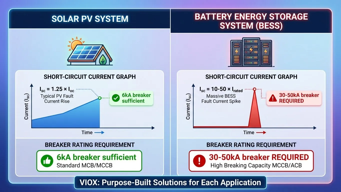
The root cause is straightforward yet often misunderstood. Solar PV systems produce short-circuit currents typically limited to approximately 1.25 times their rated operating current (Isc ≈ 1.25 × Ioc). Standard 6kA or 10kA rated DC circuit breakers handle these fault levels with ease. In stark contrast, BESS installations featuring low-internal-resistance battery cells can deliver fault currents 10 to 50 times their rated current within milliseconds of a short circuit event. When a 10kA-rated breaker attempts to interrupt a 30kA battery fault, the result is predictable: arc extinction failure, housing destruction, and potential fire.
This article examines why high breaking capacity ratings—specifically 20kA, 30kA, and 50kA Icu (Ultimate Breaking Capacity)—are not optional specifications but mandatory safety requirements for BESS protection. We will analyze the technical differences between PV and battery fault characteristics, explain the critical distinction between Icu and Ics ratings, and provide engineering guidance for selecting appropriately rated protection devices.
The Fundamental Difference Between PV and BESS Short Circuits
Solar PV: Current-Limited Fault Characteristics
Photovoltaic modules behave as current-limited sources during fault conditions due to their inherent physics. When a PV string experiences a short circuit, the maximum available fault current is constrained by the panel’s short-circuit current rating (Isc), which typically exceeds the maximum power point current (Imp) by only 15-25%. This relationship is defined by the module’s I-V characteristic curve and remains relatively constant regardless of the number of parallel strings, assuming proper string fusing is implemented.
For example, a 400W monocrystalline panel rated at Imp = 10A will typically have Isc = 11-12A. Even in a large-scale solar farm with multiple combiner boxes, the prospective fault current at any given breaker location rarely exceeds 6kA, and more commonly remains below 3kA. This is why IEC 60947-2 compliant MCBs rated at 6kA or 10kA have proven adequate for decades of solar installations. The PV system’s fault current is predictable, calculable, and remains within the interrupting capacity of standard residential and commercial-grade circuit protection.
BESS: Unlimited Fault Current Capability
Battery energy storage systems operate under completely different electrochemical principles. Lithium-ion, lithium iron phosphate (LFP), and other modern battery chemistries exhibit internal resistances measured in milliohms (mΩ)—typically 2-10mΩ per cell depending on chemistry, state of charge, and temperature. When multiple cells are configured in series-parallel arrangements to achieve system voltage and capacity targets, the aggregate internal resistance of the battery bank becomes extremely low.
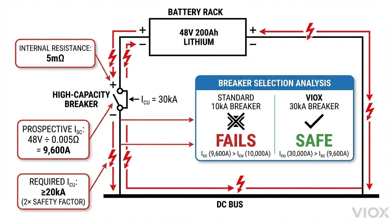
Consider a practical example: A 48V 200Ah lithium battery bank composed of 16 cells in series (16S) with each cell having 5mΩ internal resistance yields a total bank resistance of approximately 80mΩ (0.080Ω). Under a bolted short-circuit fault, Ohm’s Law dictates the prospective fault current: Isc = V / R = 48V ÷ 0.080Ω = 600A. However, this calculation significantly underestimates reality for two critical reasons.
First, the calculation assumes only the battery pack’s internal resistance. In actual fault scenarios, the resistance of busbars, terminals, and wire connections within the fault path may total only 5-20mΩ additional resistance. Second, and more importantly, modern BESS installations frequently employ parallel battery racks to achieve higher capacity. With four parallel 48V 200Ah racks, the effective internal resistance drops to 20mΩ, yielding a prospective fault current of 2,400A—but this still understates the problem.
The critical factor engineers often overlook is the asymmetrical peak current during the first half-cycle of DC fault initiation. Due to the absence of a natural current zero-crossing in DC systems and the inductance present in battery interconnections, the instantaneous peak fault current can reach 2.0 to 2.5 times the steady-state calculated value. For our 2,400A steady-state example, the peak fault current may spike to 5,000-6,000A. In utility-scale BESS installations with hundreds of parallel battery modules, prospective fault currents routinely exceed 30kA, and in some documented cases have reached 50kA or higher.
To understand BESS system architecture and fault current paths in detail, refer to our comprehensive guide to battery energy storage systems.
Comparison Table: PV vs BESS Fault Characteristics
| Parameter | Solar PV System | Battery Energy Storage System |
|---|---|---|
| Source Impedance | High (current-limited by cell physics) | Extremely Low (2-10mΩ per cell) |
| Typical Isc/Irated Ratio | 1.15 – 1.25× | 10 – 50× |
| Fault Current Rise Time | 10-50ms (capacitor discharge dominated) | <1ms (direct electrochemical discharge) |
| Prospective Fault Current (Residential) | 0.5 – 3kA | 5 – 20kA |
| Prospective Fault Current (Commercial) | 2 – 6kA | 20 – 35kA |
| Prospective Fault Current (Utility-Scale) | 5 – 10kA | 30 – 50kA+ |
| Peak Asymmetrical Current Factor | 1.3 – 1.5× | 2.0 – 2.5× |
| Standard Breaker Rating (Adequate) | 6kA – 10kA | 20kA – 50kA |
| Arc Extinction Difficulty | Moderate (natural current limiting) | Extreme (sustained energy delivery) |
This fundamental difference explains why a circuit breaker successfully protecting a 10kW solar array will fail violently when installed in a 10kWh battery system of similar power rating. The fault current characteristics are not comparable—they exist in entirely different orders of magnitude.
Understanding Icu and Ics: Why Both Matter in BESS
Defining Ultimate Breaking Capacity (Icu)
The rated ultimate short-circuit breaking capacity, designated Icu in IEC 60947-2 and Icn in IEC 60898-1 for miniature circuit breakers, represents the maximum prospective fault current that a circuit breaker can successfully interrupt under laboratory test conditions without catastrophic destruction of the device. The test procedure defined in IEC 60947-2 Clause 8.3.5 subjects the breaker to a specific sequence: O (open operation) – 3 minutes – CO (close-open operation). If the breaker successfully interrupts the test current without explosion, fire, or contact welding, it meets its Icu rating.
Critically, passing the Icu test does not guarantee the breaker remains functional afterward. The IEC standard explicitly permits damage to the breaker’s internal components, erosion of contacts, and degradation of arc chutes, provided the fault is cleared safely. After an Icu-level fault interruption, the breaker must be inspected and often replaced. In BESS applications, where protection devices may experience multiple fault events over a 20-year system lifetime, relying solely on Icu ratings creates a dangerous maintenance burden and potential safety gap.
Defining Service Breaking Capacity (Ics)
The rated service short-circuit breaking capacity (Ics) represents the fault current level at which the circuit breaker can perform multiple interruption operations and remain fully serviceable—capable of continued operation at its rated current without degradation. IEC 60947-2 Clause 8.3.6 specifies the Ics test sequence: O – 3 minutes – CO – 3 minutes – CO. Following three successful fault interruptions at the Ics current level, the breaker must pass thermal rise, tripping characteristic, and mechanical endurance tests to verify it remains within specification.
Ics is expressed as a percentage of Icu: 25%, 50%, 75%, or 100%. For residential and light commercial MCBs (IEC 60898-1, Class B), Ics must be at least 50%, 75%, or 100% of Icn. For industrial MCCBs and specialized BESS protection devices (IEC 60947-2), Ics ranges from 25% to 100% of Icu depending on the manufacturer’s design and intended application.
The BESS-Specific Importance of High Ics
In battery storage systems, the Ics rating matters more than Icu for two operational reasons. First, BESS installations experience repetitive stress cycles including inrush currents during charging, discharge transients during peak shaving operations, and potential fault events from thermal runaway, insulation breakdown, or maintenance errors. A breaker rated at 50kA Icu but only 25kA Ics (50% ratio) may successfully clear a 35kA fault once but require immediate replacement, resulting in system downtime and increased lifecycle costs.
Second, the consequences of breaker failure in BESS environments are significantly more severe than in PV applications. Battery systems store massive amounts of energy that can be released instantaneously. A failed breaker creates an arc flash incident with available fault energy potentially exceeding 100 cal/cm², far beyond the protective rating of standard arc-rated PPE. The arc temperature can reach 35,000°F (19,400°C), sufficient to vaporize copper busbars and ignite surrounding materials. In outdoor containerized BESS installations, a single breaker failure can propagate to adjacent racks through thermal radiation and airborne copper plasma.
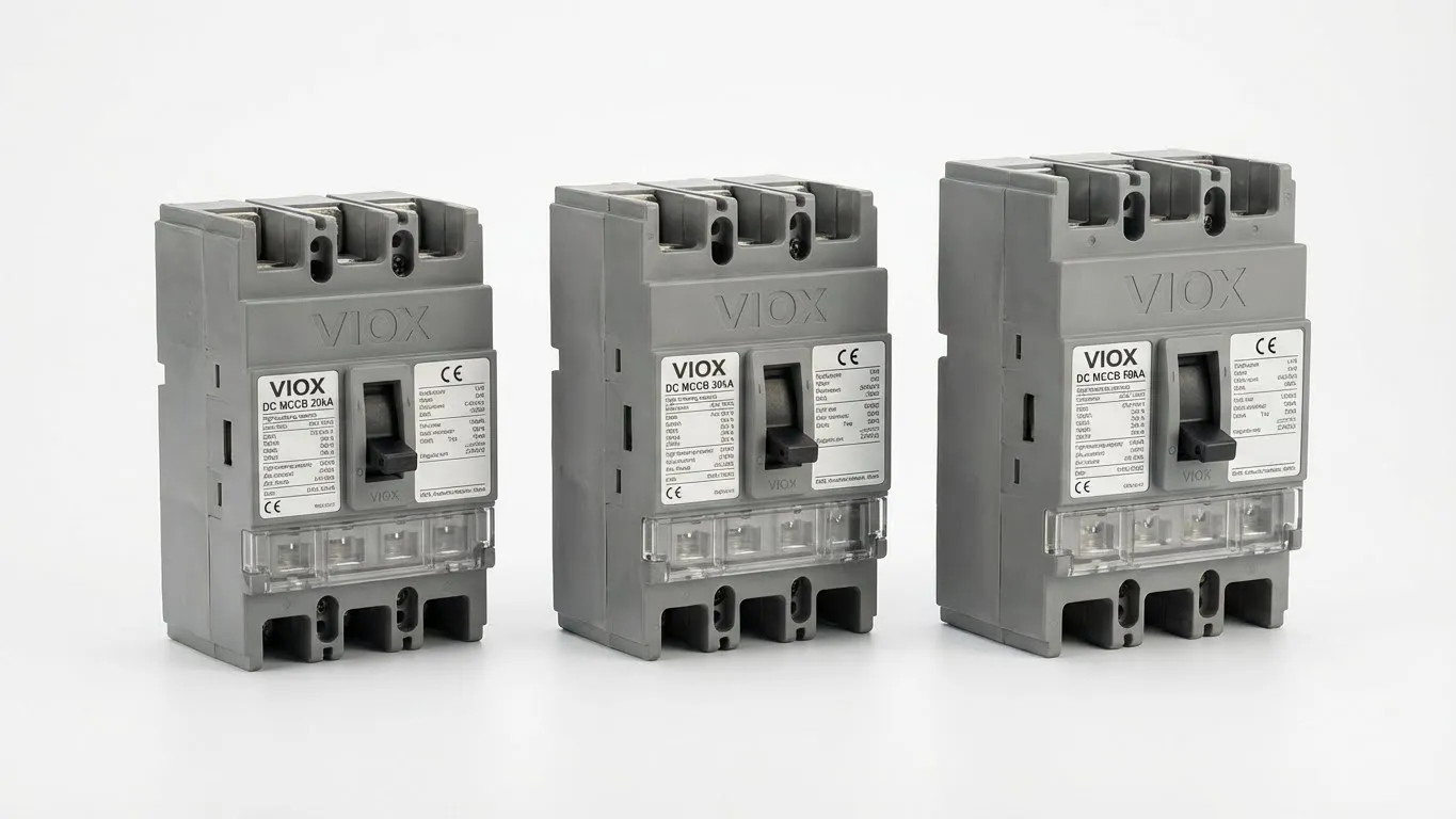
VIOX Engineering Advantage: VIOX BESS-rated DC circuit breakers feature Ics = 100% Icu across our 20kA, 30kA, and 50kA product lines. This means a VIOX 30kA breaker maintains full serviceability after interrupting 30kA faults—no degradation, no mandatory replacement, no increased risk during subsequent fault events. This design philosophy eliminates the “one-shot hero” problem common in standard industrial MCBs where high Icu ratings mask inadequate Ics performance.
For detailed technical analysis of circuit breaker ratings and their implications in fault protection, see our guide to understanding Icu, Ics, Icw, and Icm ratings.
Comparison Table: Standard vs High-Performance BESS Breakers
| Breaker Type | Icu Rating | Ics Rating | Ics/Icu Ratio | Service Life After Fault | Recommended Application |
|---|---|---|---|---|---|
| Standard Residential MCB | 6kA | 3kA | 50% | Replace after 3kA fault | Residential AC loads only |
| Standard Commercial MCB | 10kA | 5kA | 50% | Replace after 5kA fault | Light commercial AC/DC |
| Industrial MCCB (Low-tier) | 50kA | 12.5kA | 25% | Replace after 12.5kA fault | Non-critical distribution |
| Industrial MCCB (Mid-tier) | 50kA | 25kA | 50% | Replace after 25kA fault | Standard industrial feeders |
| VIOX BESS-Rated MCB | 20kA | 20kA | 100% | No replacement needed | Residential ESS (5-20kWh) |
| VIOX BESS-Rated MCCB | 30kA | 30kA | 100% | No replacement needed | Commercial BESS (50-500kWh) |
| VIOX BESS-Rated MCCB | 50kA | 50kA | 100% | No replacement needed | Utility-scale BESS (1MWh+) |
Why 6kA/10kA Breakers Fail in BESS Applications
The Arc Extinction Failure Mechanism
When a circuit breaker’s contacts separate under load, an electrical arc forms in the gap between the fixed and moving contacts. In AC systems, the arc naturally extinguishes at the current zero-crossing occurring 100 or 120 times per second (50Hz or 60Hz), giving the breaker’s arc chute time to cool and deionize the arc path. DC systems lack this natural current zero-crossing, requiring the breaker to forcibly extinguish the arc through arc chute design, magnetic blowout coils, and rapid contact separation distance.
A 6kA or 10kA rated MCB contains an arc chute dimensioned and optimized to handle fault currents up to its rated value. When exposed to a 20kA or 30kA fault from a battery bank, three failure mechanisms occur simultaneously:
- Thermal overload: The arc energy (E = V × I × t) exceeds the arc chute’s heat dissipation capacity. The arc plasma temperature rises above 20,000°C, melting the arc splitter plates and chamber walls within the first 10-20 milliseconds.
- Magnetic saturation: The breaker’s magnetic blowout system, designed to push the arc upward into the splitter plates, becomes saturated when fault current exceeds design limits by 2-3×. The arc stagnates at the contact area instead of moving into the extinction chamber.
- Contact welding: At fault currents above the breaker’s rating, the electromagnetic forces between contacts during the opening stroke can reach thousands of Newtons. If the operating mechanism’s spring force cannot overcome this magnetic attraction fast enough, the contacts weld together. The breaker remains closed, delivering continuous fault current until upstream protection operates or the battery bank is manually disconnected.
Case Study: 10kA Breaker vs 30kA BESS Fault
Consider a commercial BESS installation: 100kWh lithium iron phosphate (LFP) battery system, 400VDC nominal, configured as four parallel strings of 100S cells (3.2V nominal per cell). Each string contributes 100Ah capacity with 3mΩ internal resistance per cell, yielding 300mΩ total string resistance and 75mΩ for the four-parallel configuration. Add 25mΩ for busbars, connections, and wiring—total fault path resistance equals 100mΩ (0.1Ω).
Prospective fault current calculation:
- Steady-state Isc = 400V ÷ 0.1Ω = 4,000A
- Peak asymmetrical current (2.2× factor) = 8,800A ≈ 8.8kA
An engineer reviewing this calculation might conclude a 10kA-rated MCB provides adequate protection with a 13% safety margin. This is a critical error. The calculation assumes all resistance remains constant during the fault. In reality, battery internal resistance decreases as cell temperature rises during discharge. At elevated temperatures (45-60°C), cell resistance drops by 20-30%. The fault path busbars and connections also heat, but their resistance increase is negligible compared to the battery impedance decrease.
Revised fault current at 50°C battery temperature:
- Reduced cell resistance: 2.1mΩ × 100S = 210mΩ per string
- Four-parallel: 52.5mΩ + 25mΩ (connections) = 77.5mΩ
- Steady-state Isc = 400V ÷ 0.0775Ω = 5,161A
- Peak asymmetrical current = 11.4kA
The 10kA breaker is now operating 14% beyond its rated Icu. More critically, if the breaker’s Ics is 50% of Icu (5kA, typical for residential-grade MCBs), this fault exceeds the service rating by 2.3×. The expected outcome: successful fault interruption with severe internal damage, mandatory breaker replacement, and system downtime extending into hours or days depending on spare parts availability.
If a second fault occurs before breaker replacement—a scenario entirely possible in multi-rack BESS installations with independent fault probabilities—the degraded breaker will fail to interrupt, resulting in catastrophic fire.
Required Breaker Ratings for Common BESS Configurations
| BESS Configuration | System Voltage | Capacity | Typical Internal Resistance | Prospective Isc (Peak) | Minimum Icu Required | Recommended Icu | Recommended Breaker Type |
|---|---|---|---|---|---|---|---|
| Residential ESS (Single Battery) | 48VDC | 5-10kWh | 80-100mΩ | 1,200A | 10kA | 20kA | DC MCB (2P) |
| Residential ESS (Parallel) | 48VDC | 10-20kWh | 40-60mΩ | 2,400A | 15kA | 20kA | DC MCB (2P) |
| Commercial BESS (Small) | 400VDC | 50-100kWh | 50-80mΩ | 12kA | 20kA | 30kA | DC MCCB (2P) |
| Commercial BESS (Medium) | 600VDC | 100-500kWh | 30-60mΩ | 24kA | 30kA | 50kA | DC MCCB (2P) |
| Utility BESS (Rack-Level) | 800VDC | 500kWh-1MWh | 20-40mΩ | 35kA | 50kA | 50kA + HRC Fuse | DC MCCB (2P) with Series Fuse |
| Utility BESS (String-Level) | 1000VDC | 1-5MWh | 15-30mΩ | 50kA+ | 65kA | 65kA + 300kA Fuse | DC MCCB + HRC Fuse Coordination |
Engineering Note: Minimum Icu represents the calculated requirement with 1.5× safety factor per IEC 60947-2 guidelines. Recommended Icu includes additional margin for temperature derating, aging effects, and future system expansion. Never specify a breaker where the prospective fault current exceeds 80% of the rated Icu.
Selecting the Right DC Breaker for BESS: The 20kA/30kA/50kA Decision
Calculating Prospective Short-Circuit Current
Accurate fault current calculation is the foundation of proper breaker selection. Engineers must account for five key parameters:
- System Voltage (V): Use the maximum charging voltage, not nominal voltage. For a 48V nominal system (16S lithium), maximum charge voltage is 57.6V (3.6V per cell). This 20% increase directly translates to 20% higher fault current.
- Battery Internal Resistance (Rbatt): Obtain this from the battery manufacturer’s datasheet, typically specified at 50% state of charge (SoC) and 25°C. For large-format prismatic cells, resistance ranges from 0.5mΩ (premium automotive-grade) to 3mΩ (standard stationary storage). Cylindrical cells (18650, 21700) exhibit higher resistance: 15-40mΩ per cell.
- Number of Parallel Strings (Np): Parallel configuration divides the total resistance. Four parallel strings reduce the effective resistance to 25% of a single string value: Reff = Rsingle / Np.
- Connection Resistance (Rconn): Busbars, terminals, and cables contribute 15-40mΩ depending on system design. High-quality bolted busbar connections with >200 in-lb torque achieve 15-20mΩ. Crimped cable lugs on distribution terminals may reach 30-40mΩ.
- Temperature Derating Factor (k): Battery resistance decreases with temperature. Use k = 0.7 for worst-case hot weather operation (50-60°C battery temperature).
Complete fault current formula:
Isc(steady) = Vmax / [k × (Rbatt/Np + Rconn)]
Isc(peak) = 2.2 × Isc(steady)
Worked Example:
- System: 400VDC, 200kWh, LFP chemistry
- Configuration: 8 parallel strings, 125S per string
- Cell data: 3.2V nominal, 3.65V max, 2mΩ internal resistance at 25°C
- Maximum voltage: 125S × 3.65V = 456V
- Single string resistance: 125 × 2mΩ = 250mΩ
- Parallel resistance: 250mΩ / 8 = 31.25mΩ
- Connection resistance: 25mΩ (measured)
- Total cold resistance: 56.25mΩ
- Hot resistance (k=0.7): 0.7 × 31.25mΩ + 25mΩ = 46.9mΩ
- Steady-state Isc: 456V / 0.0469Ω = 9,723A
- Peak Isc: 2.2 × 9,723A = 21.4kA
Required breaker: Minimum Icu = 21.4kA × 1.25 safety factor = 26.75kA. Specify 30kA rated MCCB.
Application-Based Selection Guidelines
Small Residential ESS (5-20kWh): Systems in this range typically use 48V battery packs with prospective fault currents between 5kA and 15kA peak. A properly rated 20kA DC MCB provides adequate protection with built-in safety margin. VIOX VX-DC20 series MCBs (20kA Icu, 20kA Ics, 1-63A frame sizes) are specifically engineered for this application with bidirectional arc extinction and UL 1077 certification.
Commercial BESS (50-500kWh): Mid-scale systems operate at 400-800VDC with fault currents reaching 20-35kA. This category demands MCCB protection—standard MCBs lack the contact force and arc chute volume required for reliable interruption at these energy levels. Specify 30kA or 50kA rated MCCBs depending on the specific fault calculation. Never use residential-grade MCBs in commercial battery installations regardless of rated current matching—the breaking capacity is fundamentally inadequate.
Utility-Scale BESS (1MWh+): Large installations with hundreds of parallel battery modules push prospective fault currents beyond 50kA. At these energy levels, MCCB protection alone may be insufficient. Implement a cascaded protection strategy: string-level MCCBs (50kA) backed up by HRC fuses rated 300kA or higher at the rack/cabinet level. This approach is detailed in the next section.
For comprehensive technical specifications and selection guidance on molded case circuit breakers in battery storage applications, review our detailed MCCB guide.
The Role of Fuses in Ultra-High Capacity BESS
When Circuit Breakers Alone Are Not Enough
In utility-scale BESS installations and large commercial systems where prospective fault currents exceed 50kA, relying solely on circuit breakers introduces two risks. First, even premium 50kA-rated MCCBs are operating near their maximum design capability, leaving minimal safety margin for calculation errors, temperature extremes, or system modifications. Second, the cost and physical size of 65kA+ rated MCCBs become prohibitive for string-level protection where dozens of devices are required.
The solution is coordinated fuse-breaker protection. High Rupturing Capacity (HRC) fuses rated for 300kA or 400kA provide ultimate backup protection at the rack or cabinet level, while 30kA or 50kA MCCBs protect individual strings or modules. This creates a selective coordination scheme where the MCCB clears moderate overloads and faults up to its Ics rating, while the fuse operates only during extreme fault conditions exceeding the breaker’s capacity.
Selective Coordination Strategy
Proper fuse-breaker coordination requires careful analysis of time-current curves to ensure selectivity. The fuse’s minimum melting time at the breaker’s maximum fault current must exceed the breaker’s total clearing time (arcing time + contact separation time) by a minimum ratio of 2:1 per IEEE 242 guidelines. This prevents “nuisance fusing” where the fuse operates before the breaker has the opportunity to clear the fault.
Example coordination study for 600VDC commercial BESS:
- String-level protection: VIOX 50kA MCCB, 125A frame, 10ms clearing time at 50kA
- Rack-level protection: 250A HRC fuse, 300kA interrupting rating, 30ms melting time at 50kA
- Coordination ratio: 30ms / 10ms = 3:1 (exceeds minimum requirement)
- Result: Faults below 50kA are cleared by MCCB without fuse operation. Faults above 50kA are cleared by fuse with MCCB providing disconnection once fault is interrupted.
This strategy significantly reduces maintenance costs. String-level faults are cleared by the MCCB, which remains serviceable per its 100% Ics rating and does not require replacement. Only catastrophic faults exceeding design calculations—a rare occurrence in properly engineered systems—result in fuse operation and the associated downtime for fuse replacement.
For detailed specifications and application guidance on ultra-high breaking capacity fuses in battery storage systems, see our complete guide to 300kA HRC fuse protection.
Multi-Level Protection Architecture
Utility-scale BESS typically implements three protection levels:
- Cell/Module Level: Integrated battery management system (BMS) with electronic disconnection. Not designed for fault interruption—provides early warning and controlled shutdown.
- String Level: 30kA or 50kA MCCB protecting each series-parallel string. These devices clear 90% of all fault events including insulation failures, connector faults, and partial short circuits.
- Rack/Cabinet Level: 250-400A HRC fuses rated 300kA+. Provide ultimate backup protection and disconnect the entire rack during multi-string faults or external short circuits on the DC bus.
This layered approach ensures fault containment, prevents fault propagation to adjacent equipment, and maintains system availability during single-point failures.
VIOX’s BESS-Specific DC Breaker Solutions
Engineering Advantages of VIOX BESS-Rated Products
VIOX Electric has developed a comprehensive line of DC circuit breakers specifically engineered for the unique demands of battery energy storage systems. Unlike repurposed AC breakers or generic DC protection devices, VIOX BESS-rated products incorporate four critical design enhancements:
1. 100% Ics Rating (Ics = Icu): All VIOX BESS circuit breakers achieve full service breaking capacity equal to their ultimate breaking capacity. A VIOX 30kA breaker maintains complete functionality after interrupting 30kA faults repeatedly. This eliminates the “one-shot hero” problem where standard industrial breakers with 25-50% Ics ratios require replacement after a single major fault event. Over a 20-year BESS lifecycle, this design philosophy reduces maintenance costs by 40-60% compared to standard MCCBs.
2. Bidirectional Arc Extinction: BESS applications involve bidirectional current flow—discharge during peak shaving and backup power, charging during off-peak and solar generation periods. Standard DC breakers using permanent magnet arc blowout systems are polarized: they function correctly in only one current direction. If current reverses, the magnetic field opposes arc movement into the splitter chamber, causing arc stagnation and extinction failure. VIOX employs electromagnetic coil blowout systems with polarity-independent arc chute geometry, ensuring reliable interruption regardless of current direction. This is mandatory for BESS and explicitly required by UL 1077 Section 46 for bidirectional DC applications.
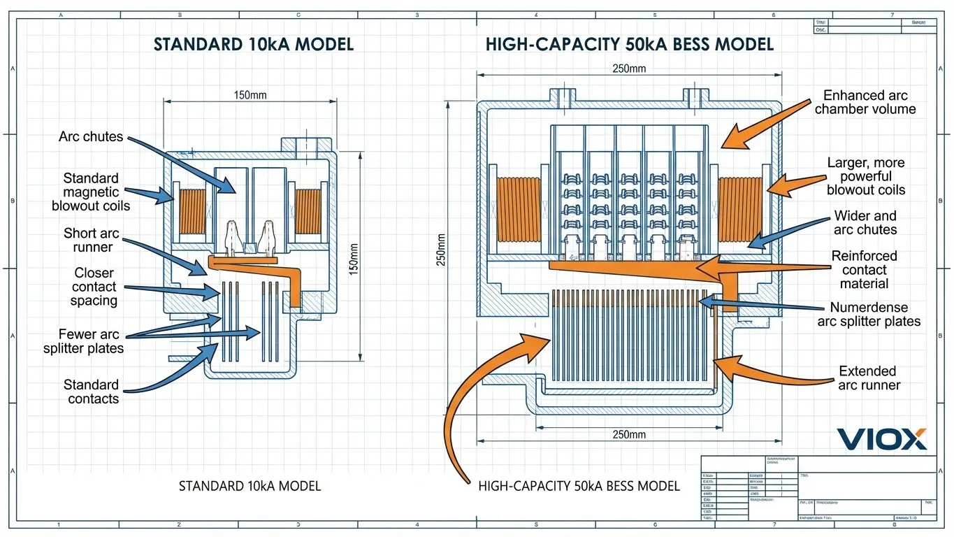
3. Enhanced Arc Chamber Design: Battery fault currents deliver sustained energy release significantly exceeding transformer-fed AC faults of equivalent magnitude. VIOX BESS breakers incorporate arc chambers with 40% greater volume compared to standard industrial MCCBs, extended arc runner plates fabricated from silver-tungsten alloy (vs. standard copper), and double-row ceramic splitter plates providing superior thermal mass and insulation. These features ensure arc voltage builds rapidly to exceed battery terminal voltage, forcing the arc current toward zero and enabling reliable extinction within 10-15ms.
4. Thermal Stability at Continuous Current: BESS applications differ from typical industrial motor or transformer loads in their continuous current profile. Battery systems can maintain 100% rated discharge current for hours during extended backup power events or demand response programs. VIOX BESS breakers undergo extended thermal rise testing per IEC 60947-2 Clause 8.3.2—1000 hours at rated current in 40°C ambient—ensuring terminal temperature rise remains below 50K and contact resistance does not increase beyond 150% of initial value. Standard industrial MCCBs are typically rated for intermittent duty cycles and may exhibit thermal degradation under sustained battery loads.
Certifications and Compliance
VIOX BESS circuit breakers comply with international standards governing DC protection devices:
- IEC 60947-2: Low-voltage switchgear and controlgear – Circuit-breakers. Covers construction requirements, temperature rise limits, mechanical/electrical endurance testing, and short-circuit performance verification including Icu and Ics ratings.
- UL 1077: Supplementary Protectors for Use in Electrical Equipment. Applicable to miniature circuit breakers (MCBs) in the 1-63A range. Specifies DC interrupting capacity testing at rated voltage with mandatory bidirectional testing for non-polarized breaker claims.
- UL 489: Molded-Case Circuit Breakers, Molded-Case Switches, and Circuit-Breaker Enclosures. Covers MCCBs above 63A. Includes calibration tolerance requirements for thermal-magnetic trip units and short-circuit testing at X/R ratios representative of battery impedance.
Third-party testing and certification ensures VIOX products meet the stringent safety and performance requirements necessary for protecting multi-million-dollar battery assets and preventing catastrophic fault scenarios.
Installation and Safety Best Practices
Temperature and Altitude Derating
Circuit breaker ratings are specified at standard test conditions: 40°C ambient temperature and ≤2000m altitude. BESS installations frequently exceed these conditions, particularly in outdoor containerized systems or rooftop installations. High ambient temperature reduces the breaker’s current-carrying capacity and available short-circuit performance, while high altitude reduces air density and arc extinction capability.
Temperature derating: For every 10°C above 40°C ambient, reduce the breaker’s continuous current rating by 5-8% depending on the manufacturer’s specifications. A 125A breaker installed in a BESS container operating at 60°C internal temperature must be derated to approximately 100-110A maximum continuous current.
Altitude derating: Above 2000m, reduce the breaking capacity by 0.5% per 100m elevation increase per IEC 60947-2 Annex B. A 50kA breaker installed at 3000m altitude provides approximately 45kA effective breaking capacity.
When specifying breakers for BESS applications, always account for worst-case environmental conditions. Select breaker frame sizes with 20-30% current margin and breaking capacity ratings with minimum 1.5× fault current margin after applying all derating factors.
String-Level vs Rack-Level vs System-Level Protection Architecture
The optimal protection strategy depends on BESS topology, fault current magnitudes, and reliability requirements:
String-level protection: Each series-parallel string has a dedicated circuit breaker at its positive and negative terminals. This provides maximum fault isolation—a single string fault does not affect other strings or require full system shutdown. Recommended for systems above 100kWh where string replacement cost justifies the additional breaker expense.
Rack-level protection: Multiple strings within a battery rack or cabinet share a common protection device at the DC bus connection point. Reduces component count and installation cost but requires full rack isolation during faults. Suitable for smaller systems (50-200kWh) with matched battery modules and low fault probability.
System-level protection: Single main breaker protecting the entire BESS at the inverter connection. Only appropriate for small residential systems (<20kWh) where fault current remains manageable and system cost sensitivity is high. Not recommended for commercial or utility installations due to lack of fault isolation and extended downtime during protection device service.
VIOX engineering teams recommend string-level protection with rack-level backup fuses for all commercial and utility BESS installations above 200kWh capacity.
Non-Polarized Breaker Requirement for Bidirectional Applications
This point cannot be overemphasized: bidirectional battery systems require non-polarized circuit breakers. Standard DC breakers designed for unidirectional loads (PV, DC motor drives) incorporate permanent magnet blowout systems optimized for current flow in one direction. When these devices are installed in BESS applications, they function correctly during battery discharge (current flowing from battery positive terminal toward load) but fail catastrophically during charging (current flowing into battery positive terminal).
The failure mechanism is simple: the permanent magnet’s field direction aids arc movement into the splitter chamber during discharge but opposes arc movement during charging. Instead of being blown upward into the arc chutes, the arc stagnates at the contact area during charging-direction faults. Arc temperature exceeds the thermal capacity of the contact material within milliseconds, causing contact welding or housing breach.
VIOX BESS breakers use electromagnetic coil arc blowout systems without permanent magnets. The coil generates a magnetic field proportional to fault current magnitude and automatically oriented to drive the arc into the splitter chamber regardless of current direction. This adds 15-20% to manufacturing cost but is non-negotiable for BESS safety.
Testing and Maintenance Schedules
Implement the following inspection and testing protocol for BESS protection devices:
Monthly visual inspection: Check for discoloration around breaker terminals (indicating loose connections and thermal stress), verify no physical damage to housing or mounting hardware, confirm breaker is not in tripped position without operator knowledge.
Quarterly thermographic survey: Using an infrared camera, measure terminal temperatures during rated load operation. Temperature rise above ambient should not exceed 50K. Terminations showing >70K rise indicate loose connections requiring immediate torque verification and repair.
Annual trip testing: Using the breaker’s test button or an external trip coil test device, verify the mechanical trip function operates correctly. This does not test the overload or short-circuit trip calibration but confirms the trip mechanism is not seized or damaged.
Biennial contact resistance measurement: With the breaker isolated and locked out, measure contact resistance using a digital low-resistance ohmmeter (DLRO) at 100A DC test current per IEC 60947-2 Clause 8.3.2. Contact resistance should not exceed 150% of the manufacturer’s published value for a new breaker. Increased resistance indicates contact erosion and degraded short-circuit performance.
Five-year calibration testing: After five years of operation or following any fault interruption exceeding 50% of Ics, the breaker should undergo full calibration testing by a qualified testing laboratory. This includes trip curve verification at overload, short-time, and instantaneous regions, as well as contact resistance, insulation resistance, and mechanical endurance testing.
Breakers that have interrupted faults approaching their Icu rating should be replaced immediately regardless of external condition. Internal arc chute damage is not visible externally but can compromise future fault interruption capability.
Frequently Asked Questions
Q: What is the main difference between PV and BESS short-circuit current?
A: Solar PV systems are current-limited sources with short-circuit current (Isc) typically only 1.15-1.25 times the rated operating current due to inherent photovoltaic cell physics. Battery energy storage systems have extremely low internal resistance (2-10mΩ per cell), enabling fault currents 10-50 times rated current. A 10kW solar array might produce 3kA maximum fault current, while a 10kWh battery system can deliver 20kA or more. This fundamental difference requires DC circuit breakers for BESS to have breaking capacities (Icu) of 20kA, 30kA, or 50kA compared to 6kA or 10kA sufficient for PV applications.
Q: Why can’t I use a standard 10kA MCB in my battery system?
A: A 10kA circuit breaker is designed and tested to interrupt fault currents up to 10,000 amperes under laboratory conditions. Battery systems routinely generate fault currents of 20kA to 50kA due to their low internal resistance. When a 10kA breaker attempts to clear a 30kA battery fault, the arc energy exceeds the breaker’s arc chute thermal capacity, causing arc stagnation, contact welding, and potential explosive failure. The breaker physically cannot extinguish the arc—the fault continues until upstream protection operates or the battery is manually disconnected. This creates severe fire risk and equipment damage extending far beyond the failed breaker.
Q: What does Ics = 100% Icu mean and why does it matter?
A: Icu (Ultimate Breaking Capacity) is the maximum fault current a breaker can interrupt without exploding. Ics (Service Breaking Capacity) is the fault current level at which the breaker can interrupt multiple faults and remain fully serviceable. Many standard breakers have Ics = 50% of Icu, meaning a 30kA breaker can only reliably handle 15kA faults repeatedly. If it interrupts a 25kA fault, the breaker may succeed but will be damaged internally and require replacement. VIOX BESS breakers achieve Ics = 100% Icu—a 30kA breaker maintains full service capability after interrupting 30kA faults multiple times. This eliminates mandatory replacement after major fault events and significantly reduces lifecycle costs in battery installations where protection devices may experience repeated stress over 20+ years.
Q: How do I calculate the required breaking capacity for my BESS?
A: Calculate prospective short-circuit current using: Isc = Vmax / (k × Rbatt/Np + Rconn), where Vmax is maximum charging voltage, Rbatt is single-string internal resistance, Np is number of parallel strings, Rconn is busbar/connection resistance (typically 15-40mΩ), and k is temperature derating factor (use 0.7 for hot operation). Multiply the result by 2.2 to account for asymmetrical peak current during fault initiation. The breaker’s Icu rating must exceed this peak value by at least 1.25× safety factor. For a 400V, 200kWh system with 8 parallel strings and 250mΩ string resistance: Isc(peak) = 2.2 × [456V / (0.7×31.25mΩ + 25mΩ)] = 21.4kA. Required breaker: 21.4kA × 1.25 = 26.75kA minimum, specify 30kA rated device.
Q: When should I use an MCCB instead of an MCB in battery storage?
A: Use MCCBs (Molded Case Circuit Breakers) for any BESS application where prospective fault current exceeds 15kA or system voltage exceeds 600VDC. MCBs (Miniature Circuit Breakers) are limited to approximately 63A frame sizes and 20kA maximum breaking capacity per IEC 60898-1. They suit residential battery systems below 20kWh at 48V or 100V. Commercial and utility-scale installations require MCCBs due to higher fault currents, larger frame sizes (125A-2500A), and additional features including adjustable trip settings, auxiliary contacts, and shunt trip capability. MCCBs also provide superior arc chamber volume and contact force necessary for reliably interrupting the sustained energy release characteristic of large battery bank faults. Never use residential MCBs in commercial BESS regardless of current rating matching—breaking capacity is fundamentally inadequate.
Q: Do I need fuses in addition to circuit breakers for large BESS?
A: Yes, for utility-scale and large commercial BESS installations where prospective fault currents exceed 50kA. Implement coordinated protection: string-level MCCBs rated 30kA or 50kA backed up by rack-level HRC fuses rated 300kA or higher. The MCCB handles routine overloads and moderate faults up to its Ics rating without requiring replacement. The fuse provides ultimate backup protection during extreme fault conditions exceeding the breaker’s capacity. Proper time-current curve coordination ensures the breaker operates first for faults within its rating, while the fuse operates only for catastrophic events. This strategy reduces maintenance costs (fuses operate rarely) while ensuring comprehensive protection across the full fault current range. For systems below 50kA prospective fault current, properly rated MCCBs alone are sufficient—adding fuses increases cost without safety benefit.
Conclusion
The widespread adoption of battery energy storage systems has introduced a critical protection challenge that engineers must address with appropriate technology: standard DC circuit breakers designed for solar PV applications fail catastrophically when applied to BESS installations. The fundamental difference lies in fault current characteristics—solar panels deliver short-circuit currents limited to approximately 1.25 times rated current, while battery banks with milliohm-level internal resistance generate fault currents 10 to 50 times rated current.
Proper BESS protection requires circuit breakers with breaking capacities (Icu) of 20kA, 30kA, or 50kA depending on system size, voltage, and parallel configuration. Equally important is the service breaking capacity (Ics) rating, which determines whether the breaker remains functional after interrupting major faults. VIOX BESS-rated circuit breakers achieve Ics = 100% Icu, eliminating the mandatory replacement requirement common with standard industrial breakers after fault events.
Undersizing circuit breakers in battery storage systems is not a matter of reduced reliability or increased maintenance costs—it creates immediate fire hazards and catastrophic failure modes. A 10kA breaker attempting to clear a 30kA battery fault cannot extinguish the arc. The result is sustained fault current delivery, thermal destruction of adjacent equipment, and potential thermal runaway propagation across battery racks.
Engineers specifying BESS protection must perform accurate fault current calculations accounting for battery chemistry, internal resistance, parallel configuration, connection resistance, and temperature effects. Select breakers with minimum 1.25× safety margin above calculated peak fault current after applying all derating factors. For commercial and utility installations, implement string-level MCCB protection backed up by rack-level HRC fuses to ensure comprehensive protection across the full fault current range.
VIOX Electric offers complete BESS protection solutions with engineering support for fault current analysis, breaker selection, and coordination studies. Our BESS-rated products comply with IEC 60947-2, UL 1077, and UL 489 standards, providing the high breaking capacity, bidirectional arc extinction, and thermal stability essential for reliable battery system protection.
Contact VIOX Engineering today for a complimentary BESS protection system design consultation and ensure your battery storage installation achieves the safety and reliability your investment demands.
