Bu sayfada
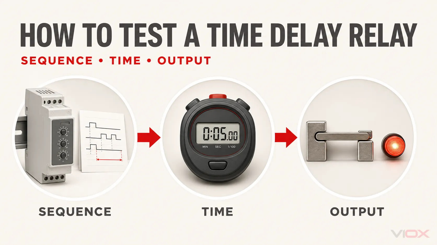
Düzgün bir zaman rölesi testi üç şeyi kontrol eder: çalışma sırası, ölçülen gecikme süresi ve çıkış durumu. Bir multimetre, voltajı ve izole kontakları doğrulamaya yardımcı olur, ancak tek başına bir zaman rölesinin tam performansını ölçemez. Duyulabilir bir tık sesi, testin başarılı olduğu anlamına gelmez.
Bu prosedür şunlara odaklanmaktadır: kontrol devrelerinde kullanılan elektronik DIN ray tipi zaman röleleri, çekmede gecikmeli ve bırakmada gecikmeli fonksiyonlar için detaylı test sıraları ile birlikte. Geçmeli tip zamanlayıcı, yarı iletken çıkışlı zamanlayıcı, pnömatik zamanlayıcı veya özel aralıklı, tekrarlayan döngülü ve yıldız-üçgen fonksiyonları farklı bir enerjili test devresi veya olay sırası gerektirebilir; kabul referansı olarak tam model dokümantasyonunu kullanın.
Pratik bir tezgah üstü test için modelin bağlantı şemasını, doğru değerlere sahip korumalı bir güç kaynağını, gerekli tetikleme cihazını, bir kronometre veya elektronik zamanlayıcıyı ve bir gösterge veya ölçü aleti kullanın. Korumalı bir temsili kontrol yükünü yalnızca bakım planı, şüpheli kontak durumu, devreye alma prosedürü veya amaçlanan görev yük altında çıkış testi gerektirdiğinde ekleyin.
Güvenlik: Test işlemleri tehlikeli voltaj ve depolanmış enerji açığa çıkarabilir. Bağlantıları değiştirmeden veya direnç/süreklilik modunu kullanmadan önce tüm kaynakları izole edin. Canlı ölçümler ve enerjili tezgah testleri, yalnızca uygun cihazlar, koruma ekipmanları ve onaylı bir prosedür kullanan yetkili personel tarafından gerçekleştirilmelidir. Zaman rölesinin kendi beslemesi kesildi diye çıkış terminallerinin güvenli olduğunu asla varsaymayın; kuru kontak ayrı bir kaynağı anahtarlıyor olabilir.
Tam model, terminal şeması, besleme değeri veya giriş tipi doğrulanamıyorsa test devresine enerji vermeyin. Röle veya soket ısıdan zarar görmüşse, canlı terminaller koruma altına alınamıyorsa veya gerekli test kaynağı ve koruma mevcut değilse işlemi durdurun.
Önemli Çıkarımlar
- Röleye enerji vermeden önce beslemeyi, tetikleme mantığını, çıkış tipini, zamanlama fonksiyonunu ve sıfırlama koşulunu tanımlayın.
- Gecikme ölçümü için bir zamanlama cihazı kullanın; multimetre voltaj ve izole kontak kontrolleri içindir.
- Güçle başlayan gecikmeli çekme (on-delay), sinyalle başlayan gecikmeli çekme, sinyalle gecikmeli bırakma (off-delay) ve gerçek enerjisiz gecikmeli bırakma testlerini farklı giriş dizilerine göre gerçekleştirin.
- Seçilen zamanlama testini tekrarlayın ve üreticinin belirttiği doğruluk kriterlerine göre değerlendirin.
- Yük altında çıkış doğrulamasını, her temel tezgah kontrolünün zorunlu bir parçası olarak değil, kontrollü ve koşullu bir test olarak ele alın.
Eksiksiz Bir Zaman Rölesi Testi Neleri Kanıtlamalıdır
Röleyi basit bir bobin ve kontak cihazı olarak ele almak yerine üç katman kullanın.
| Test katmanı | Soru yanıtlandı | yalıtımlı tornavida | Kanıt olarak ne kabul edilir |
|---|---|---|---|
| Fonksiyonel sıra | Çıkış doğru olaylarda değişiyor ve sıfırlanıyor mu? | Korumalı besleme, tetikleme anahtarı, gösterge veya sayaç | Çıkış, tam model zamanlama çizelgesini takip eder |
| Zamanlama performansı | Ölçülen gecikme süresi belgelenmiş gereksinimle eşleşiyor mu ve tutarlı bir şekilde tekrarlanıyor mu? | Kronometre, olay zamanlayıcı, osiloskop veya veri kaydedici | Kaydedilen çevrimler modele özel spesifikasyonlar dahilinde |
| Gerektiğinde çıkış durumu | Çıkış, aşırı voltaj kaybı veya kararsızlık olmadan temsili bir kontrol yükünü anahtarlayabiliyor mu? | Korumalı temsili yük, multimetre, akım sınırlamalı test kaynağı | Doğru anahtarlanmış voltaj ve kararlı yük çalışması |
Bu pratik bir fonksiyonel veya bakım testidir. Tek başına IEC 61812-1 veya başka bir ürün standardı kapsamında ürün uygunluğunu, dayanıklılığını, güvenilirliğini veya tam aralıklı zamanlama performansını kanıtlamaz.
Aletler ve Test Kurulumu
Gerekli ekipman, neyi kanıtlamanız gerektiğine bağlıdır.
| Teçhizat | Gerekli mi? | Amaç |
|---|---|---|
| Tam model veri sayfası veya terminal şeması | Evet | Besleme, giriş, çıkış, fonksiyon, sıfırlama davranışı ve kabul edilebilir zamanlama performansını tanımlar |
| Doğru değerlere sahip, korumalı test beslemesi | Enerjili bir test için evet | Zamanlayıcıyı belgelenmiş voltajında ve AC/DC tipinde besler |
| Tetikleme anahtarı veya sinyal kaynağı | Gerektiğinde | Ayrı bir kontrol girişi kullanan fonksiyonları başlatır, durdurur, geçitler veya sıfırlar |
| Test lambası veya gösterge | Önerilen | Temel çıkış işlemini görünür kılar |
| Korumalı temsili kontrol yükü | Koşullu | Test planı veya şüpheli kontak durumu gerektirdiğinde yük altında çıkış testini destekler |
| Kronometre veya elektronik olay zamanlayıcı | Zamanlama doğrulaması için evet | Başlatıcı olay ile çıkış geçişi arasındaki aralığı ölçer |
| Dijital multimetre | Önerilir, evrensel olarak zorunlu değildir | Besleme gerilimini, tetikleme gerilimini, izole sürekliliği ve anahtarlanan gerilimi kontrol eder |
| Osiloskop veya veri kaydedici | Opsiyonel | Kısa gecikmeleri, kesintili olayları, giriş sıçramalarını ve hassas geçiş zamanlamasını yakalar |
Devre için uygun değerlere sahip test ekipmanı kullanın. Küçük bir gösterge yalnızca temel anahtarlamayı doğrular.
Adım 1: Testten önce röleyi tam olarak tanımlayın
Muhafaza üzerinde yazılı olan “zaman rölesi” ifadelerine güvenmek yerine tam model numarasını kaydedin. Benzer terminallere sahip iki ürün; farklı besleme gerilimleri, zamanlama fonksiyonları, tetikleme mantığı ve çıkış tipleri kullanabilir.
Veri sayfasından şu öğeleri doğrulayın:
- nominal besleme gerilimi ve bunun AC, DC veya üniversal olup olmadığı;
- besleme terminalleri ve varsa ayrı başlatma, tetikleme, kapı, engelleme veya sıfırlama girişleri;
- her bir kontrol girişinin gerilim mi yoksa kuru kontak mı beklediği;
- çıkış tipi: elektromekanik enversör kontak, yarı iletken çıkış veya başka bir düzenleme;
- COM, normalde açık (NO) ve normalde kapalı (NC) terminal tanımlaması;
- seçilen fonksiyon, zaman aralığı, başlatma olayı ve sıfırlama koşulu;
- çalışma süresi hassasiyeti, ayar hatası ve herhangi bir minimum giriş veya sıfırlama gereksinimi.
Terminal numaralarının markalar veya modeller arasında birbirinin yerine kullanılabileceğini varsaymayın. zaman rölesi bağlantı şeması kılavuzunu kullanın DIN rayı terminal grupları ile yaygın 8 pinli veya 11 pinli soket düzenlemeleri arasındaki farkları açıklar.
Adım 2: Röleyi İnceleyin ve Kontrollü Bir Test Devresi Kurun
Tüm kaynakların bağlantısı kesilmiş haldeyken muhafazayı, terminalleri, soketi, seçicileri ve ayar kontrollerini inceleyin. Çatlama, renk değişimi, erime, yanık kokusu, gevşek soket kontakları veya hasarlı terminaller olup olmadığını kontrol edin.
Testi, uygulanabilir olduğunda iki ayrı yol etrafında oluşturun:
- Zamanlayıcı besleme ve tetikleme yolu: zamanlayıcıyı besler ve seçilen zamanlama fonksiyonunu başlatır.
- Çıkış test yolu: COM'u besler ve anahtarlanmış çıkışı bir gösterge veya temsili kontrol yükü üzerinden dönüş iletkenine yönlendirir.
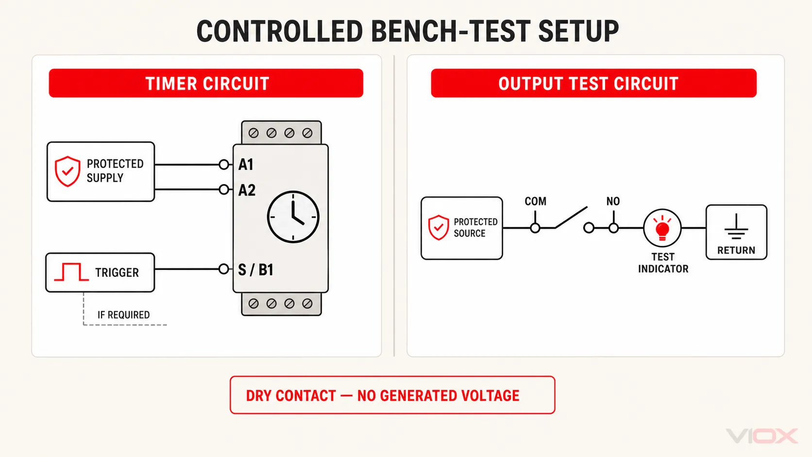
Birçok zaman rölesi çıkışı kuru kontaktır. NO veya NC uçlarında gerilim üretmezler. Bu nedenle çıkış test devresi, COM'a bağlı kendi korumalı kaynağına ihtiyaç duyar. Bu kaynak, A1 ve A2'yi besleyen kaynakla aynı olabilir veya olmayabilir; mevcut devre tasarımını ve ürün dokümantasyonunu takip edin.
Sökmeden önce iletkenleri etiketleyin. Korumalı terminaller ve akım sınırlamalı veya doğru şekilde korunmuş kaynaklar kullanın; asla açık hat gerilimi bağlantılarıyla doğaçlama yapmayın.
Adım 3: Güç Kapalıyken Sıfırlama Durumu Kontaklarını Kontrol Edin
Direnç veya süreklilik modunu seçmeden önce röleyi her türlü harici kaynaktan izole edin ve gerilim olmadığını doğrulayın.
Belgelenmiş sıfırlama durumundaki elektromekanik bir enversör çıkış için:
- COM–NC normalde kapalıdır;
- COM–NO normalde açıktır.
Ancak “normal”, üreticinin zamanlama şeması tarafından tanımlanan durumu ifade eder. Tutulan, kilitli, enerjinin kesilmesiyle gecikmeli veya tam olarak sıfırlanmamış bir zaman rölesi bu basit beklentiyle uyuşmayabilir. Sonucu değerlendirmeden önce belgelenmiş sıfırlama koşulunun gerçekleşmesine izin verin.
Ölçü aletini yalnızca izole edilmiş çıkış terminalleri üzerinde kullanın. Üretici tam model için bu prosedürü sağlamadığı sürece A1 ve A2 uçları arasında genel bir bobin direnci testi uygulamayın. Modern elektronik zaman röleleri doğrultucular, koruma bileşenleri, güç kaynağı devreleri veya AC/DC giriş elektroniği içerebilir; bu nedenle rastgele bir direnç değeri, zaman rölesinin sağlam olup olmadığını belirlemez.
Transistör veya diğer yarı iletken çıkışlar için süreklilik modu alakasız veya yanıltıcı bir sonuç verebilir. Bu çıkışı, üretici tarafından belirtilen enerjili devre, polarite, referans terminali ve yükü kullanarak test edin.
Adım 4: Besleme ve Kontrol Girişlerini Doğrulayın
Enerji vermeden önce, fonksiyonu ve zaman aralığını model talimatlarında belirtildiği şekilde tam olarak ayarlayın. Bazı üreticiler, enerji altındayken seçicilerin değiştirilmesini kısıtlar; ürün dokümantasyonuna uyun.
Enerjili ölçüme izin verildiğinde, voltajı yalnızca yukarı akış güç kaynağından değil, doğrudan zamanlayıcı besleme terminalleri üzerinden doğrulayın. Şunları teyit edin:
- ölçülen voltajın nominal besleme ve AC/DC tipi ile eşleştiğini;
- polaritenin belirtildiği durumlarda DC polaritesinin doğru olduğunu;
- zamanlayıcı ve test yükü çalışırken voltajın sabit kaldığını;
- ayrı bir başlatma veya tetikleme girişinin belgelenmiş aktif ve pasif durumlarına ulaştığını;
- sıfırlama veya kapı (gate) girişlerinin istenmeden aktif olmadığını.
Bir model kuru kontak kontrol girişi kullanıyorsa, bu girişe voltaj uygulamayın. Örneğin Macromatic, kuru kontak kontrol anahtarı tetikleyicilerini güç tetiklemeli versiyonlardan ayırır ve kuru kontak tetikleme girişine voltaj uygulamanın cihaza zarar verebileceği konusunda uyarır.
Hangi giriş olayının zamanlamayı başlatması veya durdurması gerektiğinden emin değilseniz, önce işlevi karşılaştırın Çekmede gecikmeli (on-delay) ve bırakmada gecikmeli (off-delay) zaman rölesi kılavuzu. Tezgah testi zamanlama çizelgesini birebir yansıtmalıdır; sıralama sadece fonksiyon isminden çıkarılmamalıdır.
Adım 5: Çekmede Gecikme (On-Delay) Testini Gerçekleştirin
Çekmede gecikmeli bir çıkış, durumunu ancak başlatma koşulu seçilen gecikme süresi boyunca geçerli kaldıktan sonra değiştirir.
Besleme Gerilimi ile Başlayan Çekmede Gecikme
- Zaman rölesinin tamamen sıfırlandığını doğrulayın.
- Gerekli fonksiyonu, aralığı ve gecikme süresini ayarlayın.
- COM ucu ve hedeflenen kontak üzerinden doğru çıkış test devresini kurun.
- Nominal zamanlayıcı beslemesini uygulayın ve zamanlama cihazını aynı anda başlatın.
- Gecikme süresi boyunca zamanlanmış çıkışın başlangıç durumunda kaldığını doğrulayın.
- Çıkış kontağı durum değiştirdiğinde veya test yükü çalıştığında zamanlamayı durdurun.
- Beslemeyi kesin ve çıkışın zamanlama şemasına uygun olarak sıfırlandığını doğrulayın.
Sinyal Tetiklemeli Gecikmeli Çekme (On-Delay)
- Önce zamanlayıcı beslemesini uygulayın ve stabilize edin.
- Tetikleyicinin pasif olduğunu ve çıkışın dokümante edilmiş başlangıç durumunda olduğunu doğrulayın.
- Başlatma girişini aktif edin ve zamanlama cihazını o anda başlatın.
- Çıkışın yalnızca seçilen gecikmeden sonra değiştiğini doğrulayın.
- Tetikleyiciyi kaldırın ve belgelenmiş sıfırlama davranışını kontrol edin.
Bu iki yöntemi birleştirmeyin. Sinyal başlatmalı bir zamanlayıcı, tetikleyici gelmeden önce sürekli besleme gerektirebilir; güç başlatmalı bir zamanlayıcı ise besleme yükselirken zamanlamaya başlar. Omron, güç kaynağı başlatmalı ve sinyal başlatmalı zamanlayıcıların farklı sınıflandırmalar olduğunu ve geçerli zamanlama şemasının doğru sırayı tanımladığını belirtir.
Adım 6: Gecikmeli Kapanma (Off-Delay) Testini Gerçekleştirin
“Gecikmeli kapanma” ifadesi birden fazla donanım düzenini tanımlar. Herhangi bir bağlantıyı kesmeden önce modelin hangi düzeni kullandığını belirleyin.
Sürekli Zamanlayıcı Beslemesi ile Sinyal Gecikmeli Kapanma
- Zamanlayıcı beslemesini uygulayın ve ünitenin başlatılmasına izin verin.
- Belgelenmiş tetikleyiciyi veya kontrol girişini etkinleştirin.
- Çıkışın zamanlama çizelgesinde gösterildiği gibi aktif duruma geçtiğini doğrulayın.
- Zamanlayıcı beslemesini enerjili tutarken tetikleyiciyi kaldırın.
- Tetikleyici durum değiştirdiğinde zamanlama cihazını başlatın.
- Gecikme süresince çıkışın aktif kaldığını doğrulayın.
- Çıkış serbest kaldığında zamanlamayı durdurun.
- Başka bir döngü başlatmadan önce sıfırlama durumunu doğrulayın.
Gerçek Enerji Kesilmesi Gecikmesi (True Power-Off Delay)
Gerçek bir enerji kesilmesi gecikme zamanlayıcısı, beslemesi kesildikten sonra çıkışını belirli bir süre koruyacak şekilde tasarlanmıştır. Testi yalnızca model zamanlama çizelgesine göre gerçekleştirin:
- Beslemeyi en az üretici tarafından belirtilen çalışma koşullarına uygun şekilde uygulayın.
- Çıkışın aktif durumuna ulaştığını doğrulayın.
- Beslemeyi kesin ve aynı anda zamanlamayı başlatın.
- Onaylı çıkış test devresini kullanarak korunan çıkışı gözlemleyin.
- Çıkış serbest kaldığında zamanlamayı durdurun.
- Testi tekrarlamadan önce gerekli sıfırlama veya yeniden şarj koşulunu sağlayın.
A1/A2 gücünü kesmek, bir sinyal girişini kaldırmaktan farklı bir durumu test eder. Elektronik devreler sürekli besleme gerektiriyorsa, anında sıfırlama normaldir.
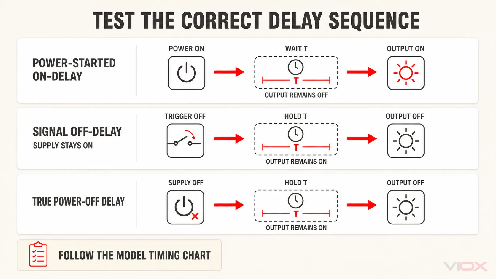
Ek aralık, darbe, tekrarlamalı döngü ve çok fonksiyonlu modların açıklamaları için, zaman röleleri tam kılavuzunu kullanın. ve ardından tam model zamanlama çizelgesini takip edin.
Adım 7: Zamanlama Doğruluğunu ve Tekrarlanabilirliğini Ölçün
Başarılı bir döngü, yalnızca çıkışın bir kez hareket ettiğini kanıtlar. Aynı kontrollü diziyi tekrarlayın ve her sonucu kaydedin.
| Döngü | Ayarlanan süre | Ölçülen gecikme | Çıkış doğru şekilde değişti mi? | Sıfırlama tamamlandı mı? | Notlar |
|---|---|---|---|---|---|
| 1 | |||||
| 2 | |||||
| 3 | |||||
| 4 | |||||
| 5 |
Bir ayar noktasında beş döngü, yalnızca pratik bir işlevsel tekrarlanabilirlik örneğidir. Bunlar, rölenin tam zamanlama aralığını karakterize etmez, güvenilirliğini veya dayanıklılığını belirlemez ya da IEC 61812-1 ile uyumluluğunu göstermez. Tam aralık doğrulaması; tanımlanmış test noktaları, uygun enstrümantasyon, kontrollü koşullar ve onaylı bir test planı gerektirir.
Faydalı tanımlayıcı hesaplamalar şunları içerir:
Ortalama gecikme = ölçülen gecikmelerin toplamı / çevrim sayısıFarkı yalnızca seçilen süreye dayanarak otomatik olarak bir geçme/kalma yüzdesine dönüştürmeyin. Üreticiler, çalışma süresi hassasiyetini veya ayar hatasını tam ölçeğin yüzdesi, ayarlanan değerin yüzdesi, sabit bir zaman terimi veya bunların bir kombinasyonu olarak belirtebilirler. Kayıtları, veri sayfasındaki tam ifadeler ve test koşulları ile karşılaştırın.
Elde taşınan bir kronometre, daha uzun gecikmelerde kaba bir fonksiyonel kontrol için uygundur, ancak operatörün tepki süresi kısa gecikmeli bir ölçümde baskın olabilir. Gerekli çözünürlük manuel bir gözlemin destekleyebileceğinden daha hassas olduğunda elektronik bir olay zamanlayıcısı, osiloskop veya veri kaydedici kullanın.
Adım 8 — Gerektiğinde: Çıkışı Temsili Bir Yük Altında Doğrulayın
Bu koşullu testi, bakım planı, devreye alma prosedürü, şüpheli kontak durumu veya amaçlanan kontrol görevi gerektirdiğinde gerçekleştirin. Temel bir fonksiyonel tezgah testi bunu her zaman gerektirmez.
Korumalı bir temsilci kullanın kontrol yükü kontrollü test devresinde. Test edilen röleyi, sadece bir tezgah testi tamamlamak amacıyla çalışan üretim ekipmanına bağlamayın.
Röle kontak çıkışı için:
- Yük voltajının, akımın, kalkış akımının ve kullanım görev döngüsünün belgelenmiş çıkış değerleri dahilinde olduğunu doğrulayın.
- COM bağlantısını amaçlanan korumalı kaynaktan besleyin.
- Zamanlama dizisini çalıştırın ve seçilen çıkış terminalindeki anahtarlanmış voltajı doğrulayın.
- Yük ve dönüş yolu üzerinde yeterli çalışma voltajı olduğunu onaylayın.
- Kararsız çalışma, titreme, aşırı voltaj kaybı veya bırakmama durumu olup olmadığını kontrol edin.
Düşük akımlı süreklilik sonucu, kontağın temsilci yükü çalıştırabileceğini kanıtlamaz. Anahtarlanmış voltaj veya yük sonucu hatalıysa, arızayı kaydedin ve özel incelemeye devam edin. zaman gecikmeli röle tık sesi çıkarıyor ancak yük çalışmıyor prosedür. Bu kılavuz; beslenmeyen bir COM terminali, yanlış NO/NC seçimi, açık dönüş yolu, yüksek dirençli kontak ve uygun olmayan yük görevi için detaylı arıza teşhisini içerir.
Hedeflenen görev, zamanlayıcı kontağının belgelenmiş değerini aşıyorsa testi durdurun ve güç yükünü doğrudan bağlamak yerine uygun değerde bir kontaktör veya ara röle belirleyin.
Adım 9: Sıfırlama, Yeniden Tetikleme ve Güç Kesintisi Davranışını Kontrol Edin
Seçilen fonksiyon için geçerli olan davranışları doğrulayın:
- başlatma sinyali kaldırıldıktan sonra sıfırlama;
- besleme kesintisinden sonra sıfırlama;
- sıfırlama girişine yanıt;
- gecikme süresi dolmadan tetikleyici kaldırıldığında verilen yanıt;
- yeniden tetiklemenin zamanlama döngüsünü yeniden başlatıp başlatmadığı, uzatıp uzatmadığı, görmezden gelip gelmediği veya sonlandırıp sonlandırmadığı;
- tamamlanmamış güç döngüsü sonrası çıkış durumu.
Kabul referansı olarak zamanlama çizelgesini kullanın. Beklenen davranışı yalnızca “on-delay” (çekmede gecikmeli) veya “off-delay” (bırakmada gecikmeli) ifadelerinden yola çıkarak tahmin etmeyin.
Adım 10: Sonucu Kaydedin ve Devreyi Eski Haline Getirin
Modeli, seçilen fonksiyonu ve aralığı, besleme ve tetikleme koşullarını, test cihazını, ölçülen döngüleri, çıkış durumunu, sıfırlama sonucunu ve varsa koşullu yük testi sonucunu kaydedin. Onay, yalnızca kaydedilen bu konfigürasyon ve test koşulu için geçerlidir.
Testten sonra:
- Tüm tezgah üstü test kaynaklarının bağlantısını kesin ve gerilim olmadığını doğrulayın.
- Geçici köprüleri, göstergeleri ve temsili test yüklerini kaldırın.
- Etiketli iletkenleri onaylı kurulum şemasına göre eski haline getirin.
- Terminalleri ekipman üreticisinin talimatlarına uygun şekilde sıkın.
- Enerji vermeden önce koruyucuların ve kapakların yerine takıldığından emin olun.
- Devreyi tekrar hizmete almadan önce gerekli kurulum veya devreye alma kontrolünü tamamlayın.
Tezgah sonucu belirsiz olduğunda, kurulu devre test edilen konfigürasyondan farklı olduğunda veya kontak hasarının orijinal nedeni giderilmediğinde röleyi hizmete almayın.
Geçti/Kaldı Karar Tablosu
| Test sonucu | Yorumlama | Bir sonraki işlem |
|---|---|---|
| Besleme, tetikleme, sıralama, zamanlama, sıfırlama ve yük çıkışı dokümantasyonla tamamen uyumludur | Röle pratik fonksiyonel testten başarıyla geçmiştir | Servise ancak normal kurulum kontrolleri tamamlandıktan sonra geri dönün |
| Doğru besleme mevcut ancak güç veya zamanlama göstergesi görünmüyor | Olası dahili besleme veya elektronik arızası | Terminalleri ve modeli tekrar doğrulayın; sorun giderme prosedürünü kullanın |
| Zamanlama başlıyor ancak çıkış zamanlama şemasını takip etmiyor | Hatalı kurulum, eksik koşul veya arızalı çıkış katı | Modu, tetikleyiciyi, sıfırlamayı ve izole çıkış kontağını tekrar kontrol edin |
| Çıkış sırası doğru ancak kaydedilen zamanlama model spesifikasyonunun dışında | Ayar, besleme, ortam, ölçüm yöntemi veya zamanlayıcı hatası | Değişimden önce test koşullarını ve cihaz çözünürlüğünü doğrulayın |
| Süreklilik doğru şekilde değişiyor ancak yük çalışmıyor | Zamanlayıcı temel kontak testini tamamladı ancak çıkış yolu veya kontak yükü henüz doğrulanmadı | Kullanın tık sesi geliyor ancak yük çalışmıyor arıza teşhis prosedürü |
| Zamanlayıcı tezgahta çalışıyor ancak panoda başarısız oluyor | Kurulum beslemesi, tetikleme, parazit, priz, kablolama veya yük sorunu | Tezgah koşullarını gerçek pano koşullarıyla karşılaştırın |
| Kontak, belgelenmiş sıfırlama koşulundan sonra kapalı kalıyor | Kaynaklı kontak, tutulan fonksiyon veya eksik sıfırlama | Devreyi izole edin ve değişimden önce tam model davranışını doğrulayın |
Röle arızalanırsa, şununla devam edin: zaman gecikmeli röle çalışmama sorun giderme kılavuzu. Bu makale, dahili bir zamanlayıcı arızasını taklit edebilecek çevresel besleme, tetikleme, seçici, kablolama ve yük koşullarını teşhis eder.
Hızlı Zaman Rölesi Test Kontrol Listesi
- Tam model ve nominal besleme değerini kaydedin.
- Terminal şemasını ve zamanlama grafiğini temin edin.
- Güçle başlatma, sinyalle başlatma ve sıfırlama davranışlarını tanımlayın.
- Röle kontaklı veya yarı iletken çıkışlı olduğunu belirleyin.
- Röleyi, soketi, seçicileri ve terminalleri inceleyin.
- Gerektiğinde ayrı zamanlayıcı besleme ve çıkış yükü yolları oluşturun.
- Dokümante edilmiş sıfırlama durumu çıkışını doğrulayın.
- Doğru besleme ve tetikleme sırasını uygulayın.
- Seçilen çekmede gecikme veya bırakmada gecikme fonksiyonunu test edin; özel modlar için modele özgü prosedürü kullanın.
- Birkaç ölçülen zamanlama döngüsünü kaydedin.
- Sonuçları veri sayfasında belirtilen doğruluk temeline göre karşılaştırın.
- Sıfırlama ve yeniden tetikleme davranışını doğrulayın.
- Gerektiğinde, anahtarlanan voltajı korumalı bir temsilci kontrol yükü ile test edin.
- Röleyi servise geri döndürmeden veya değiştirmeden önce sonucu kaydedin.
Sıkça Sorulan Sorular
Bir zaman rölesini test etmek için multimetreye ihtiyacım var mı?
Her test için geçerli değildir. Korumalı bir besleme, tetikleme anahtarı, gösterge ve kronometre temel fonksiyonel zamanlamayı gösterebilir. Besleme gerilimini, tetikleme gerilimini, izole kontak sürekliliğini, anahtarlanan gerilimi veya yük üzerindeki gerilimi doğrulamanız gerektiğinde bir multimetre önerilir. Bir zamanlama cihazının veya temsili yük testinin yerini tutamaz.
Bir çekmede gecikmeli (on-delay) röleyi nasıl test ederim?
Belgelenmiş beslemeyi veya başlatma sinyalini uygulayın, bu olay anında zamanlamayı başlatın, gecikme süresince çıkışın başlangıç durumunda kaldığını doğrulayın ve zamanlanmış çıkışın ne zaman değiştiğini kaydedin. Ardından belgelenmiş sıfırlama koşulunu doğrulayın.
Bir bırakmada gecikmeli (off-delay) röleyi nasıl test ederim?
Öncelikle cihazın sinyal kontrollü bırakmada gecikmeli mi yoksa gerçek enerji kesilmesinde gecikmeli mi olduğunu belirleyin. Sinyal kontrollü bırakmada gecikmeli röle için zamanlayıcı beslemesini enerjili tutun ve kontrol sinyalini kesin. Gerçek enerji kesilmesinde gecikmeli röle için beslemeyi belirtildiği şekilde kesin. Çıkışın bırakmadan önce ne kadar süre aktif kaldığını ölçün.
Kaç tane zamanlama döngüsü test etmeliyim?
Üretici, proje şartnamesi veya saha test planı tarafından istenen numune sayısını kullanın. Beş satırlık çalışma sayfası, güvenilirlik, dayanıklılık, tam aralık veya uygunluk testi değil, pratik tekrarlanabilirlik kontrolü için bir örnektir.
Röle neden tezgahta çalışıyor da panoda arıza veriyor?
Tezgah kurulumu kararlı bir beslemeye, temiz bir tetiklemeye, sağlam terminallere ve hafif bir test yüküne sahip olabilir. Kurulu devre ise voltaj düşüşü, elektriksel gürültü, gevşek bir soket, eksik sıfırlama, endüktif parazit veya uygun olmayan bir yük getirebilir. Ölçülen pano koşullarını kontrollü tezgah kurulumu ile karşılaştırın.
Sonuç
Bir zaman rölesini aşağıdakileri doğrulayarak test edin: sıra, zaman ve çıkış durumu ayrı ayrı. Belgelenmiş besleme ve tetikleme koşullarını yeniden oluşturun, tekrarlanan çıkış geçişlerini kaydedin ve yalnızca gerektiğinde temsili bir yük kontrolü ekleyin.
Bir multimetre, voltaj ve izole kontak kontrollerini destekler; bir kronometre veya elektronik zamanlayıcı ise gecikmeyi ölçer. Hiçbir sonuç, test edilen fonksiyonun, ayar noktasının ve koşulların ötesine taşınmamalıdır.
Doğrulanmış bir arızadan sonra yedek parça seçimi için; gerekli zamanlama fonksiyonunu, beslemeyi, tetikleme yöntemini, çıkış düzenini, kontak görevini ve sıfırlama davranışını şurada karşılaştırın: zaman rölesi seçim kılavuzunu kullanın veya şurayı inceleyin: VIOX zaman rölesi serisi.