
Every year, industrial facilities lose an estimated $647 billion globally due to unplanned downtime—and improper timer relay selection accounts for 12-18% of control circuit failures. Choosing between on delay and off delay timers isn’t just a technical decision; it’s a critical factor in equipment longevity, energy efficiency, and operational safety.
Key Takeaways
- On delay timers (TON) delay output activation after input signal, preventing false starts and equipment surge damage
- Off delay timers (TOF) maintain output after input removal, ensuring proper cooling cycles and controlled shutdowns
- Time ranges span from 0.1 seconds to 999 hours across industrial-grade models
- Voltage compatibility includes 12VDC, 24VDC, 120VAC, and 240VAC configurations per IEC 61812-1 standards
- Contact ratings typically range from 5A to 16A at 250VAC for general industrial applications
- PLC programming uses TON and TOF function blocks with preset time (PT) and elapsed time (ET) parameters
What Are On Delay and Off Delay Timers?
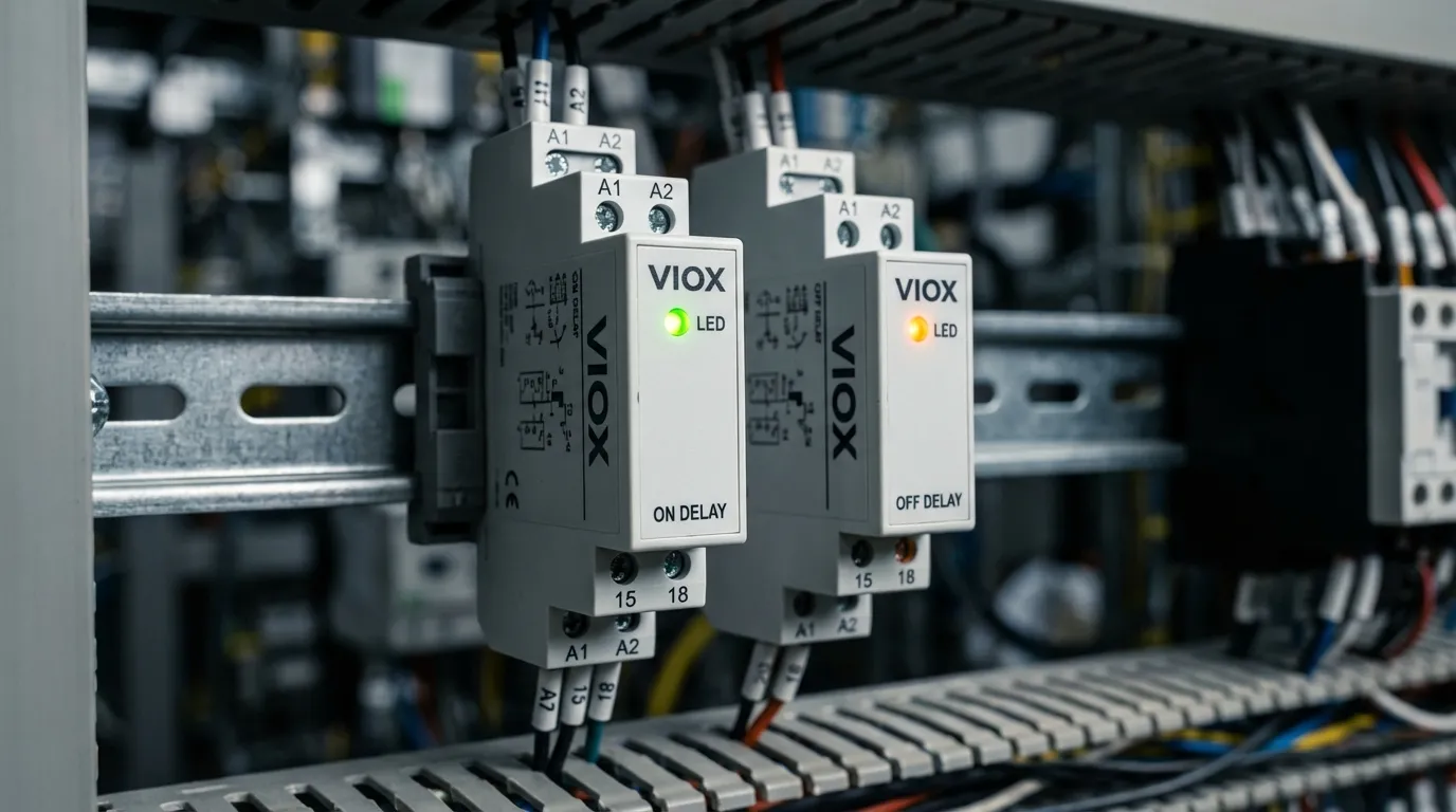
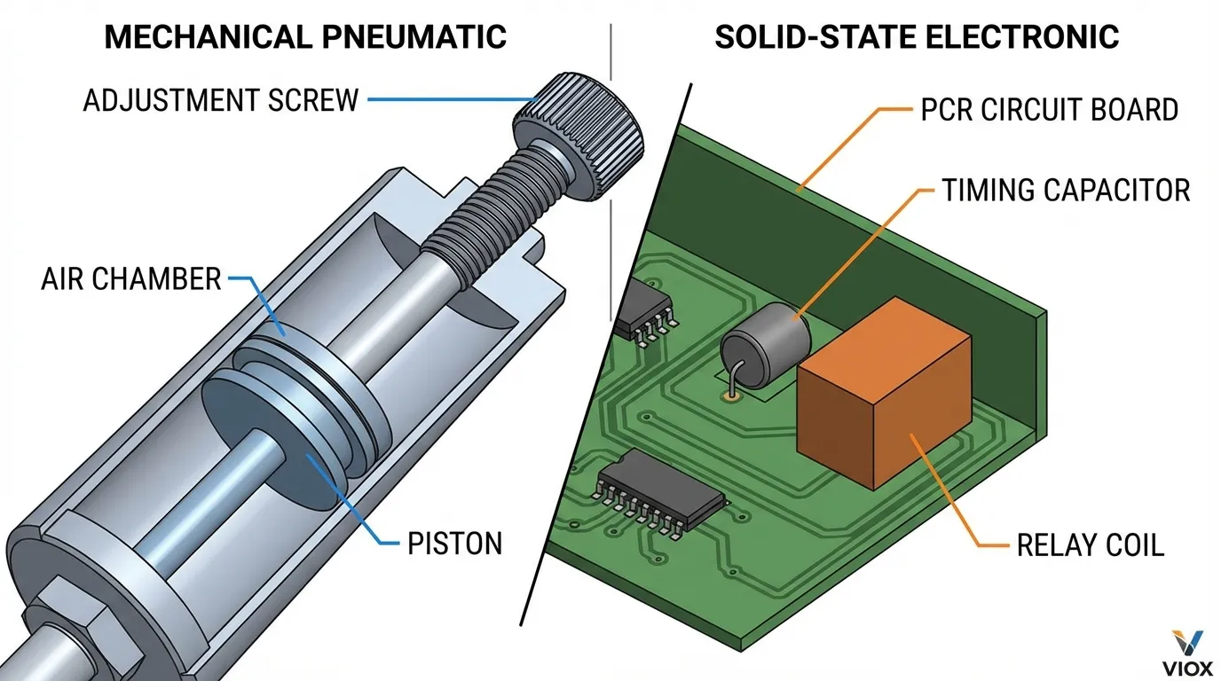
Time delay relays are electromechanical or solid-state devices that control the timing of contact operation in electrical circuits. Unlike standard relays that switch instantaneously, time delay relays introduce precise, programmable delays between input signals and output actions.
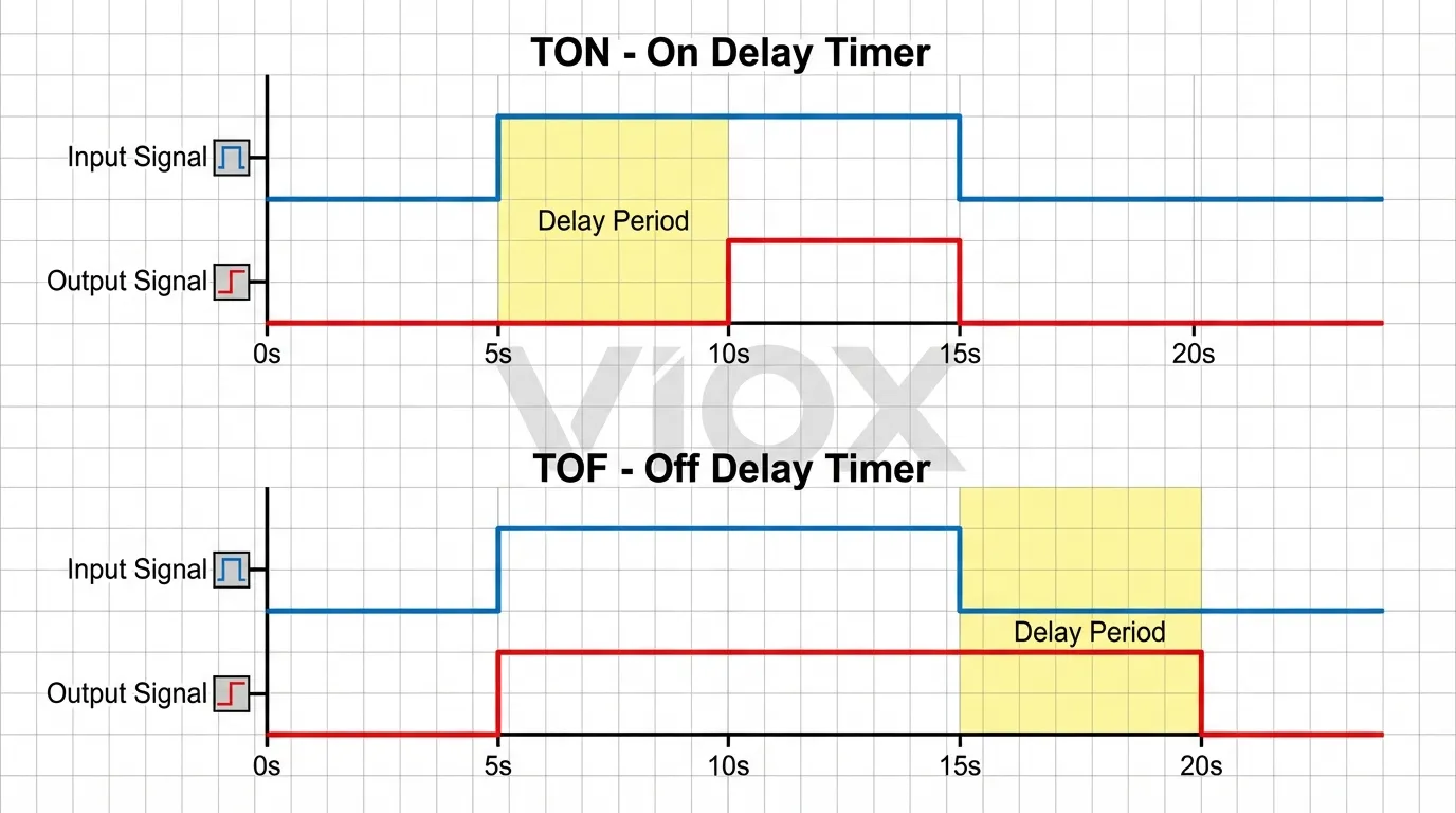
On Delay Timer (TON) – Also called “delay-on-make” or “delay-on-operate,” this timer type delays the activation of its output contacts after receiving an input signal. The output remains OFF during the preset delay period and only energizes once the timer completes its countdown.
Off Delay Timer (TOF) – Known as “delay-on-break” or “delay-on-release,” this configuration activates its output immediately when the input energizes but maintains that output for a specified duration after the input signal is removed.
Both timer types comply with IEC 61812-1 standards for industrial timing relays and UL 508 certification for North American markets.
How On Delay Timers Work (TON)
The operational sequence of an on delay timer follows four distinct phases:
Phase 1: Standby State
- Input contacts open, timer coil de-energized
- Output contacts remain in normal state (NO contacts open, NC contacts closed)
- Elapsed time (ET) = 0
Phase 2: Input Activation
- Control signal applied to timer coil (terminals A1-A2)
- Internal timing mechanism initiates countdown
- Output contacts maintain initial state
- ET begins incrementing toward preset time (PT)
Phase 3: Timing Period
- Timer counts from 0 to PT (e.g., 0 to 10 seconds)
- If input signal removed before PT reached, timer resets to ET = 0
- Output remains inactive throughout delay
Phase 4: Output Activation
- When ET = PT, output contacts change state
- NO contacts close, NC contacts open
- Output remains energized as long as input signal maintained
- Upon input removal, output immediately de-energizes and timer resets
This timing behavior makes TON timers essential for applications requiring verification of sustained demand before committing equipment to operation. Learn more about how to wire a time relay for motor starter applications.
How Off Delay Timers Work (TOF)
Off delay timers operate with an inverse logic compared to on delay types:
Phase 1: Standby State
- Input contacts open, timer coil de-energized
- Output contacts in normal state
- ET = 0, timer ready to accept trigger
Phase 2: Immediate Output Activation
- Control signal applied to terminals A1-A2
- Output contacts change state instantly (NO contacts close)
- Connected load energizes without delay
- Timer remains in standby, not yet timing
Phase 3: Input Signal Removal
- Control switch opens or input signal removed
- Output contacts remain in activated state
- Timer begins countdown from 0 to PT
- ET increments while output stays energized
Phase 4: Delayed Deactivation
- When ET reaches PT (e.g., 15 seconds), output contacts return to normal state
- NO contacts open, NC contacts close
- Connected load de-energizes
- If input reapplied during timing, most TOF relays reset and restart sequence
This behavior ensures equipment continues operating for a controlled period after the initiating signal ceases—critical for cooling cycles, material processing, and safety lighting applications.
Critical Differences: Side-by-Side Comparison
| Feature | On Delay Timer (TON) | Off Delay Timer (TOF) |
|---|---|---|
| Timing Trigger | Input signal application | Input signal removal |
| Output Behavior on Input | Delayed activation (waits PT) | Immediate activation |
| Output Behavior on Input Removal | Immediate deactivation | Delayed deactivation (waits PT) |
| Primary Function | Prevents false starts | Ensures controlled shutdown |
| Typical Time Range | 0.1s – 999h | 0.1s – 999h |
| Reset Condition | Input removal during timing | Input reapplication (model-dependent) |
| IEC Symbol | Dashed line input-to-output | Solid line input-to-output |
| PLC Function Block | TON | TOF |
| Common Applications | Motor soft start, HVAC sequencing | Cooling fan delay, emergency lighting |
| Prevents | Inrush current, false triggers | Abrupt shutdowns, thermal shock |
| Power Loss Behavior | Resets to 0 | Most models reset (check datasheet) |
| Contact Configuration | SPDT, DPDT available | SPDT, DPDT available |
Technical Specifications Comparison
| Parameter | Standard Range | Industrial Grade | Compliance Standards |
|---|---|---|---|
| Control Voltage (AC) | 24VAC, 120VAC, 240VAC | 90-265VAC universal | IEC 61812-1, UL 508 |
| Control Voltage (DC) | 12VDC, 24VDC, 48VDC | 12-48VDC range | IEC 61812-1 |
| Time Adjustment Range | 0.1s – 30min | 0.05s – 999h | IEC 60255 |
| Timing Accuracy | ±5% at 25°C | ±2% at 25°C | IEC 61812-1 |
| Contact Rating (Resistive) | 5A @ 250VAC | 10A @ 250VAC | UL 508, IEC 60947-5-1 |
| Contact Rating (Inductive) | 3A @ 250VAC (cosφ 0.4) | 5A @ 250VAC | IEC 60947-5-1 |
| Mechanical Life | 10 million operations | 30 million operations | IEC 61810-1 |
| Electrical Life | 100,000 operations @ rated load | 300,000 operations | IEC 61810-1 |
| Operating Temperature | -10°C to +55°C | -25°C to +70°C | IEC 60068-2 |
| Mounting Type | DIN rail (35mm), panel mount | DIN rail, socket, PCB | IEC 60715 |
| Protection Rating | IP20 (standard) | IP40, IP54 (industrial) | IEC 60529 |
| Dielectric Strength | 2000VAC (1 minute) | 4000VAC (1 minute) | IEC 61812-1 |
Real-World Applications by Industry
Manufacturing & Industrial Automation
Conveyor Belt Sequencing (TON Application)
- Problem: Simultaneous motor startup causes voltage sag and breaker trips
- Solution: On delay timers stagger motor activation in 3-5 second intervals
- Settings: PT = 3-5s per motor, 24VDC control voltage
- Result: Reduces inrush current by 60-75%, prevents nuisance tripping
Machine Tool Cooling (TOF Application)
- Problem: Spindle motors require coolant circulation after shutdown to prevent thermal warping
- Solution: Off delay timer maintains coolant pump operation post-machining
- Settings: PT = 120-180s, 120VAC control
- Result: Extends spindle bearing life by 40%, reduces thermal distortion
HVAC Systems
Compressor Anti-Short-Cycle Protection (TON)
- Prevents compressor restart within 3-5 minutes of shutdown
- Protects against liquid refrigerant slugging and bearing damage
- Typical setting: PT = 180-300s
- Complies with ASHRAE 15 safety standards
Exhaust Fan Purge Cycle (TOF)
- Maintains ventilation fan operation after equipment shutdown
- Ensures complete fume/heat evacuation from enclosures
- Typical setting: PT = 60-120s
- Meets NFPA 70 (NEC) Article 430.44 requirements
Motor Control Applications
Star-Delta Starter Transition (TON)
- Delays transition from star to delta configuration during motor startup
- Reduces starting current to 33% of direct-on-line starting
- Typical setting: PT = 5-15s depending on motor inertia
- Reference: Star Delta Starter Wiring Diagram
Cooling Fan Post-Run (TOF)
- Maintains fan operation after motor shutdown for thermal management
- Prevents bearing damage from residual heat
- Typical setting: PT = 30-90s
- Critical for motors >10HP in enclosed environments
Safety & Emergency Systems
Emergency Lighting (TOF)
- Keeps egress lighting active after power interruption
- Provides time for backup generator startup or safe evacuation
- Typical setting: PT = 30-60s
- Complies with NFPA 101 Life Safety Code
Fire Suppression Delay (TON)
- Provides verification period before activating suppression systems
- Prevents false discharge from transient smoke detector signals
- Typical setting: PT = 10-30s
- Meets NFPA 72 fire alarm code requirements
| Industry/Application | Timer Type | Typical PT Range | Key Benefit |
|---|---|---|---|
| Motor soft start | TON | 3-10s | Reduces inrush current |
| Cooling fan delay | TOF | 30-180s | Prevents thermal shock |
| HVAC sequencing | TON | 30-300s | Staggers equipment startup |
| Emergency lighting | TOF | 30-90s | Maintains illumination |
| Pump alternation | TON | 1-60s | Equalizes wear |
| Conveyor sequencing | TON | 2-5s | Prevents overload |
| Compressor protection | TON | 180-300s | Anti-short-cycle |
| Ventilation purge | TOF | 60-300s | Ensures air exchange |
Wiring Methods and Circuit Diagrams
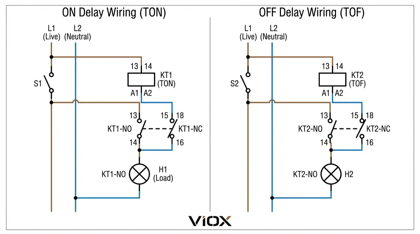
On Delay Timer Wiring (120VAC Control)
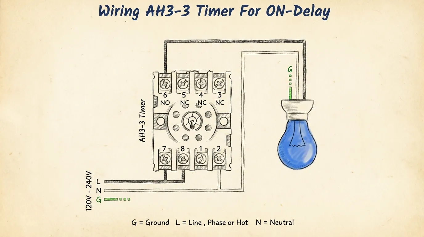
Terminal Connections:
- A1, A2: Control voltage input (120VAC from control switch)
- 15-18: Normally Open (NO) timed contact
- 15-16: Normally Closed (NC) timed contact
- Load: Connected between contact 18 and L2 (neutral)
Operational Sequence:
- Close control switch → 120VAC applied to A1-A2
- Timer begins countdown (e.g., PT = 10s)
- After 10s, contact 15-18 closes, energizing load
- Open control switch → contact 15-18 opens immediately, load de-energizes
Off Delay Timer Wiring (24VDC Control)
Terminal Connections:
- A1 (+), A2 (-): DC control voltage (24VDC from PLC output)
- 15-18: NO timed contact
- 15-16: NC timed contact
- Load: Connected through contact 15-18
Operational Sequence:
- PLC output HIGH → 24VDC applied to A1-A2
- Contact 15-18 closes immediately, load energizes
- PLC output LOW → timer begins countdown (e.g., PT = 15s)
- After 15s, contact 15-18 opens, load de-energizes
Critical Wiring Notes:
- Always verify coil voltage matches control circuit voltage
- Use appropriately rated wire gauge for contact current (14 AWG for 15A circuits)
- Install surge suppression (RC snubber or MOV) across inductive loads
- Follow NEC Article 430.72 for motor control circuit protection
- Ensure proper grounding per IEC 60364-5-54
For comprehensive wiring guidance, see Timer Relay Voltage Selection Guide.
PLC Programming: TON vs TOF Instructions
Modern PLCs implement timer functions as standardized IEC 61131-3 function blocks. Understanding these blocks is essential for industrial automation.
TON Function Block (On Delay)
Standard Parameters:
- IN (BOOL): Input trigger signal
- PT (TIME): Preset time value (e.g., T#10S for 10 seconds)
- Q (BOOL): Output status (TRUE when ET ≥ PT)
- ET (TIME): Elapsed time since IN went TRUE
Ladder Logic Example:
|--[ ]--[TON]--( )--|
   IN    PT=T#5S  Q
         ET
Operational Logic:
- When IN transitions FALSE → TRUE, ET begins incrementing
- Q remains FALSE until ET = PT
- If IN returns to FALSE before ET = PT, timer resets (ET = 0, Q = FALSE)
- Q stays TRUE as long as IN = TRUE and ET ≥ PT
Typical Applications:
- Motor starter delay to allow contactor settling
- Sensor debouncing (PT = T#100MS)
- Sequential machine startup
TOF Function Block (Off Delay)
Standard Parameters:
- IN (BOOL): Input trigger signal
- PT (TIME): Preset time value
- Q (BOOL): Output status (TRUE when IN = TRUE OR timing active)
- ET (TIME): Elapsed time since IN went FALSE
Ladder Logic Example:
|--[ ]--[TOF]--( )--|
   IN    PT=T#15S Q
         ET
Operational Logic:
- When IN = TRUE, Q immediately becomes TRUE (ET = 0)
- When IN transitions TRUE → FALSE, ET begins incrementing
- Q remains TRUE during timing period
- When ET = PT, Q transitions to FALSE
- If IN returns to TRUE during timing, ET resets to 0 and Q stays TRUE
Typical Applications:
- Cooling fan post-run after motor shutdown
- Stairwell lighting with occupancy sensor
- Pump run-on after flow switch opens
PLC Platform Variations:
- Siemens S7: TON/TOF in IEC timer library (T#format)
- Allen-Bradley: TON/TOF with .PRE (preset) and .ACC (accumulator) tags
- Schneider: TON/TOF with %TMi addressing
- Mitsubishi: T (timer) instruction with K constant for preset
For detailed PLC programming examples, explore Time Delay Relays Complete Guide.
Selection Guide: When to Use Each Type
Choose ON DELAY (TON) When:
✅ Preventing False Starts
- Momentary signals should not trigger equipment
- Verification of sustained demand required
- Example: Pressure switch with 5s verification delay
✅ Sequencing Equipment Startup
- Multiple motors must start in timed intervals
- Prevents simultaneous inrush current
- Example: Conveyor system with 3-motor sequence
✅ Debouncing Mechanical Contacts
- Switch bounce causes multiple triggers
- Clean signal required for downstream logic
- Example: Limit switch with 100ms debounce
✅ Safety Interlocks
- Guard door must remain closed for set duration before machine start
- Prevents bypass of safety systems
- Example: 3-second door verification before press cycle
Choose OFF DELAY (TOF) When:
✅ Controlled Equipment Shutdown
- Gradual deactivation prevents damage
- Allows completion of mechanical cycles
- Example: Spindle coolant pump 120s post-run
✅ Thermal Management
- Cooling required after equipment shutdown
- Prevents bearing/component damage
- Example: Motor cooling fan 60s delay
✅ Maintaining Illumination
- Lighting should remain on briefly after occupancy signal ends
- Provides safe egress time
- Example: Stairwell lights 45s after motion detection
✅ Process Completion
- Material must fully clear before next cycle
- Ensures quality and prevents jams
- Example: Packaging line discharge conveyor 30s run-on
Decision Tree Approach
Question 1: Does the load need to activate immediately when the control signal appears?
- YES → Consider TOF (immediate activation, delayed deactivation)
- NO → Consider TON (delayed activation)
Question 2: Is the delay needed at startup or shutdown?
- Startup → TON
- Shutdown → TOF
Question 3: Are you preventing false triggers or ensuring complete cycles?
- Preventing false triggers → TON
- Ensuring complete cycles → TOF
Question 4: What happens if power is lost during timing?
- Must reset and restart → Standard TON/TOF
- Must resume from last state → Retentive timer (RTO) required
For comprehensive relay selection criteria, reference How to Choose the Right Timer Relay.
Common Mistakes and Troubleshooting
| Problem | Likely Cause | Solution | Prevention |
|---|---|---|---|
| Timer doesn’t start timing | Incorrect coil voltage | Verify voltage with multimeter; check nameplate rating | Always confirm coil voltage matches control circuit |
| Output activates immediately (TON) | Wiring error – TOF mode selected | Check mode selector switch/jumper; verify against datasheet | Label timer type clearly during installation |
| Timer resets prematurely | Input signal unstable/bouncing | Add RC filter (0.1µF + 10kΩ) across input terminals | Use contact debouncing for mechanical switches |
| Inconsistent timing | Temperature variation affecting accuracy | Relocate timer away from heat sources; use temperature-compensated model | Maintain ambient temp within ±10°C of calibration temp |
| Contacts welding/failing | Exceeding contact rating | Measure actual load current; add contactor for loads >80% rating | Always derate contacts to 70-80% of maximum rating |
| Timer doesn’t reset after power loss | Capacitor-based timer retaining charge | Discharge timing capacitor (short A1-A2 for 5s with power off) | Use electronic timers with guaranteed reset on power loss |
| Erratic operation in noisy environment | EMI/RFI interference | Install ferrite core on control wires; use shielded cable; add MOV suppression | Route control wiring away from VFDs, contactors, welders |
Advanced Troubleshooting Techniques
Measuring Timing Accuracy:
- Apply rated control voltage to A1-A2
- Use stopwatch or oscilloscope to measure actual delay
- Compare to preset time (PT)
- Acceptable tolerance: ±5% per IEC 61812-1
- If outside tolerance, check for voltage variation or replace timer
Contact Resistance Testing:
- De-energize circuit and disconnect load
- Energize timer to close contacts
- Measure resistance across NO contacts with milliohm meter
- Acceptable: <50mΩ for new contacts, <200mΩ for aged contacts
- > 200mΩ indicates oxidation/wear—replace timer
Insulation Resistance Testing:
- De-energize and disconnect all wiring
- Apply 500VDC between coil and contacts using megohmmeter
- Acceptable: >100MΩ per IEC 61810-1
- <10MΩ indicates insulation breakdown—replace immediately
FAQ
What is the main difference between on delay and off delay timers?
The fundamental difference lies in when the timing delay occurs. An on delay timer (TON) delays the activation of its output after the input signal is applied—the output waits for the preset time before turning ON. An off delay timer (TOF) activates its output immediately when the input is applied but delays the deactivation—the output waits for the preset time before turning OFF after the input is removed. In practical terms: TON = “wait before starting,” TOF = “keep running after signal ends.”
When should I use a TON timer instead of a TOF timer?
Use a TON timer when you need to verify that a condition is sustained before committing equipment to operation. This is critical for:
- Preventing false starts from momentary signals (pressure spikes, voltage transients)
- Sequencing equipment to stagger startup and reduce inrush current
- Safety interlocks requiring verification periods (guard doors, two-hand controls)
- Debouncing mechanical switches to eliminate contact bounce
Use a TOF timer when you need equipment to continue operating after the initiating signal ends:
- Cooling cycles for motors, compressors, or heat-generating equipment
- Process completion ensuring materials fully clear before shutdown
- Emergency lighting maintaining illumination during power transitions
- Ventilation purge cycles after equipment shutdown
Can I use an on delay timer for motor cooling applications?
No—using a TON timer for motor cooling is incorrect and potentially damaging. Motor cooling requires the fan to continue running after the motor stops, which is an off delay (TOF) function. A TON timer would delay the fan startup when the motor starts, providing no cooling benefit. The correct configuration is:
- Motor contactor auxiliary contact → TOF timer input
- TOF timer output → Cooling fan contactor coil
- Preset time: 60-180 seconds depending on motor size and duty cycle
This ensures the fan runs immediately when the motor starts and continues for the preset time after the motor stops. For detailed motor control wiring, see Contactors vs Relays: Understanding the Key Differences.
What voltage should I choose for my time delay relay?
Voltage selection depends on your control circuit standard:
- 24VDC – Most common for PLC-controlled systems, low-voltage safety circuits, and modern industrial automation. Advantages: Safe, noise-immune, compatible with electronic controls.
- 120VAC – Standard for North American residential/light commercial and direct switch control without transformers.
- 240VAC – Used in European/international installations (230VAC), heavy industrial equipment, and three-phase motor control circuits.
- 12VDC – Specialized applications like automotive, mobile equipment, and battery-powered systems.
- Universal voltage (90-265VAC/DC) – Best for international equipment, uncertain voltage environments, and flexibility in installation.
Always verify the control voltage available at the installation location before ordering. For comprehensive guidance, reference Timer Relay Voltage Selection Guide: 12V, 24V, 120V, 230V.
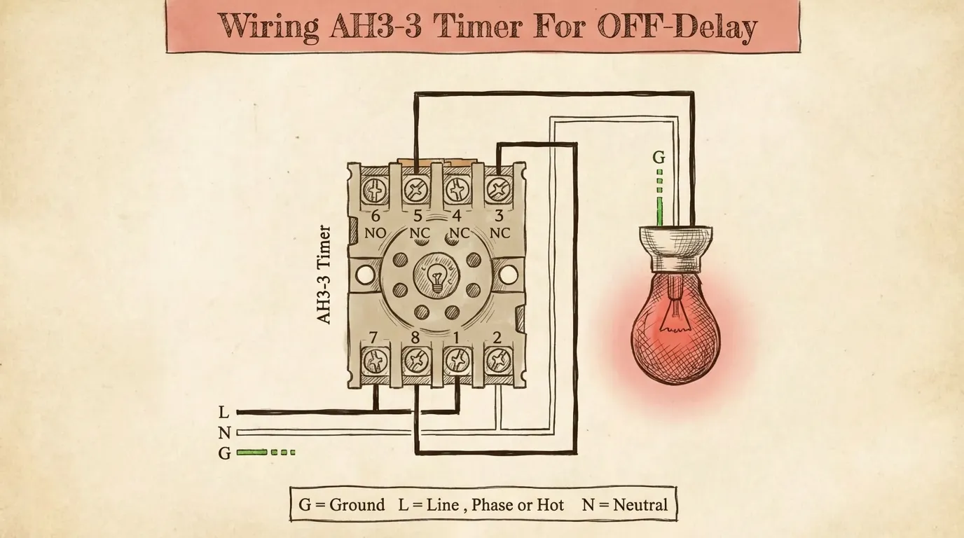
How do I wire an off delay timer in a control circuit?
Basic OFF Delay Wiring (120VAC):
- Power Supply: Connect L1 (hot) and L2 (neutral) to control circuit
- Control Switch: Wire control switch in series with L1
- Timer Coil: Connect A1 to control switch output, A2 to L2
- Load Connection: Wire load between timer NO contact (terminal 18) and L2
- Common Terminal: Connect timer common (terminal 15) to L1
Operation: When control switch closes, timer coil energizes and contact 15-18 closes immediately, powering the load. When control switch opens, the load remains powered for the preset time, then de-energizes.
Critical Safety Notes:
- Use appropriately rated wire (14 AWG minimum for 15A circuits)
- Install overcurrent protection per NEC Article 430.72
- Add surge suppression across inductive loads (MOV or RC snubber)
- Ensure proper grounding of control panel per NEC Article 250
For visual wiring diagrams and step-by-step procedures, see What is a Time Relay.
What are common failure modes of time delay relays?
1. Contact Failure (40% of failures)
- Symptoms: Intermittent operation, no output despite timing complete
- Causes: Exceeding contact rating, inductive load without suppression, environmental contamination
- Prevention: Derate contacts to 70-80% of rating, use contactors for heavy loads, install in IP54+ enclosures
2. Timing Drift (25% of failures)
- Symptoms: Actual delay doesn’t match preset, inconsistent timing
- Causes: Capacitor aging (electromechanical timers), temperature extremes, voltage variation
- Prevention: Use electronic timers with crystal oscillators, maintain stable ambient temperature, regulate control voltage
3. Coil Burnout (20% of failures)
- Symptoms: No response to input signal, coil resistance infinite
- Causes: Overvoltage, sustained overcurrent, insulation breakdown
- Prevention: Verify voltage compatibility, use fused control circuits, avoid moisture exposure
4. EMI/RFI Interference (10% of failures)
- Symptoms: Erratic timing, false triggering, premature resets
- Causes: Proximity to VFDs, contactors, welders, or radio transmitters
- Prevention: Use shielded control cables, install ferrite cores, separate control and power wiring by >12 inches
5. Mechanical Wear (5% of failures)
- Symptoms: Increasing contact resistance, delayed contact closure
- Causes: Exceeding mechanical life rating, vibration, shock
- Prevention: Select timers with appropriate mechanical life rating, use vibration dampening mounts
Conclusion
Selecting between on delay and off delay timers requires understanding the fundamental timing behavior: TON delays activation, while TOF delays deactivation. This seemingly simple distinction has profound implications for equipment protection, energy efficiency, and operational safety.
Key Decision Factors:
- Application requirement: Startup control (TON) vs. shutdown control (TOF)
- Voltage compatibility: Match control circuit voltage (12VDC to 240VAC)
- Contact rating: Ensure adequate capacity with 20-30% safety margin
- Time range: Verify preset range covers your application (0.1s to 999h)
- Environmental conditions: Select appropriate IP rating and temperature range
- Standards compliance: Verify IEC 61812-1, UL 508, or equivalent certification
VIOX Time Delay Relays offer comprehensive solutions for both on delay and off delay applications, featuring:
- Universal voltage inputs (90-265VAC/DC) for installation flexibility
- Wide timing ranges (0.05s to 999h) covering virtually all industrial applications
- High-capacity contacts (10A @ 250VAC) with extended electrical life
- IEC 61812-1 and UL 508 certified for global compliance
- DIN rail mounting for rapid installation and maintenance
For technical consultation on timer relay selection for your specific application, contact VIOX technical support at [email protected] or visit our product selection guide.
