On this page
The five most consequential MCB busbar installation mistakes are assuming that similar-looking devices are compatible, clamping a tooth incorrectly, using the wrong terminal method or tightening value, modifying a busbar without manufacturer approval, and restoring power without a complete isolation and verification process. Preventing them requires evidence from the exact breaker and busbar instructions—not appearance, brand familiarity, or a universal rule of thumb.
Safety boundary: Work inside a distribution board exposes people to shock, arc, fire, and unexpected-energization hazards. Installation, testing, and restoration should be performed by a qualified electrical worker under the applicable local rules, equipment instructions, and site isolation procedure. Do not work energized merely to follow this guide.
The five checks at a glance
| Installation mistake | What must be verified | Pass condition | Stop condition |
|---|---|---|---|
| Assuming the MCB and busbar are compatible | Device family, terminal geometry, pitch, pole/phase pattern, rating, and accessories | Every interface is supported by the exact product documentation | Compatibility depends on appearance, nominal module width, or an unverified cross-brand claim |
| Mis-seating a pin or fork tooth | Tooth position, insertion depth, clamp contact, and row alignment | The conductor is fully in the intended terminal contact zone with no insulation under the clamp | A tooth is forced, tilted, only partly engaged, or the sleeve is trapped in the terminal |
| Using the wrong terminal method or torque | Approved feed method, conductor-sharing rule, tool, sequence, and model-specific tightening value | The connection follows the exact terminal diagram and published value for that model | The value or shared-terminal arrangement cannot be confirmed |
| Cutting or leaving exposed ends incorrectly | Whether cutting is permitted, phase sequence, cut treatment, end cap, and unused-tooth protection | The manufacturer-approved method and matching accessories produce a clean, enclosed result | The busbar is non-cuttable, damaged, contaminated, or lacks the specified end protection |
| Energizing without full verification | Isolation, absence of voltage, visual/mechanical checks, phase arrangement, covers, and restoration control | All documented checks are complete and the assembly is ready for the site’s commissioning process | Any test point, barrier, accessory, connection, or result is unresolved |
This is an acceptance framework, not a substitute for the exact device instructions. If a row contains mixed device families, auxiliaries, RCBOs, RCDs, spare positions, or more than one supply arrangement, the documentation check becomes more important—not less.
Mistake 1: Assuming every DIN-rail MCB fits the same comb busbar
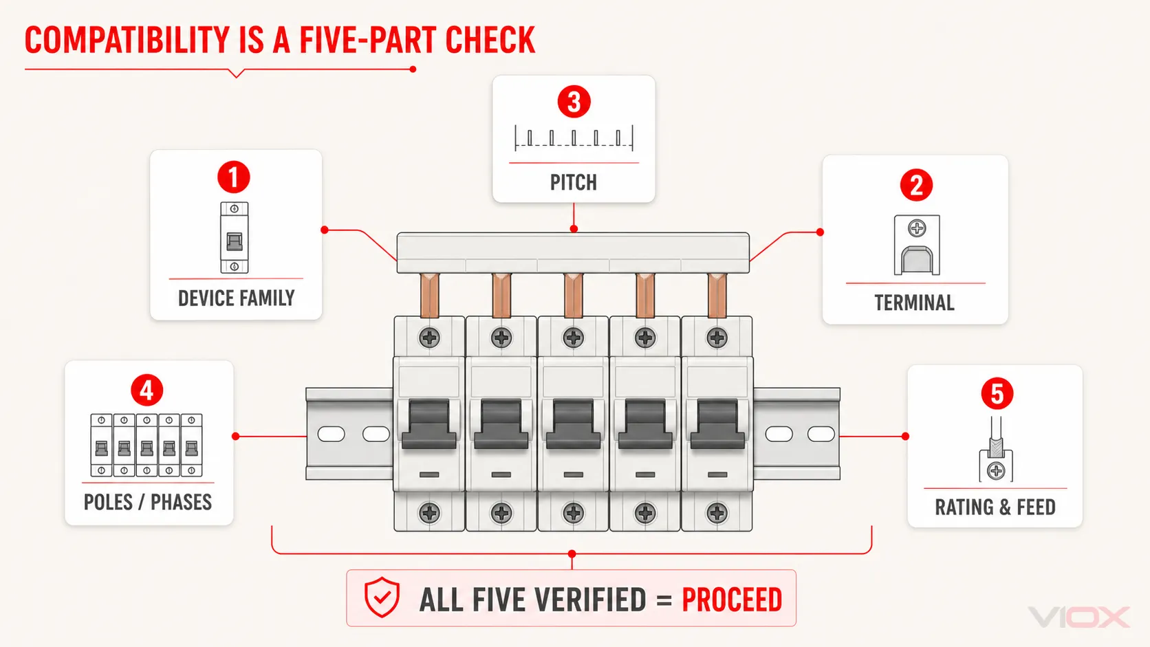
Two modular devices can share the same nominal width and still have different terminal openings, clamp geometry, tooth position, insertion depth, phase sequence, or approved accessories. A pin or fork that appears to enter a terminal is not proof that the electrical contact area, insulation clearances, and mechanical retention are correct.
Why it fails
The busbar-to-terminal interface must carry the row current through the contact arrangement the manufacturer designed. A geometry mismatch can leave a tooth partly clamped, load the terminal unevenly, distort the row, or put insulation where the conductive surface should be. These are assembly defects even when the devices sit neatly on the DIN rail.
What to inspect
- Exact MCB, RCD, RCBO, switch, auxiliary, and busbar series—not only the brand name.
- Pin, fork, or product-specific interface and the terminal intended for it.
- Module pitch, number of poles, and repeating phase pattern across the complete row.
- Busbar rated current, cross-section, length, permitted feed arrangement, and number of modules.
- Required feeder terminals, connectors, end caps, tooth caps, or other accessories.
- Published permission for any mixed-device or cross-family combination.
The MCB busbar compatibility guide provides the deeper model-matching workflow, while the MCB and comb busbar selection guide covers the broader specification inputs.
Correct action and stop condition
Build a row schedule with exact product codes, then match it to the busbar manufacturer’s compatibility and installation documents. Stop if compatibility depends on visual fit, an unverified seller statement, or an assumption that all products from one brand use the same interface. Do not force, bend, grind, or reshape a tooth to make an unverified combination fit.
Mistake 2: Clamping the sleeve—or only part of the busbar tooth
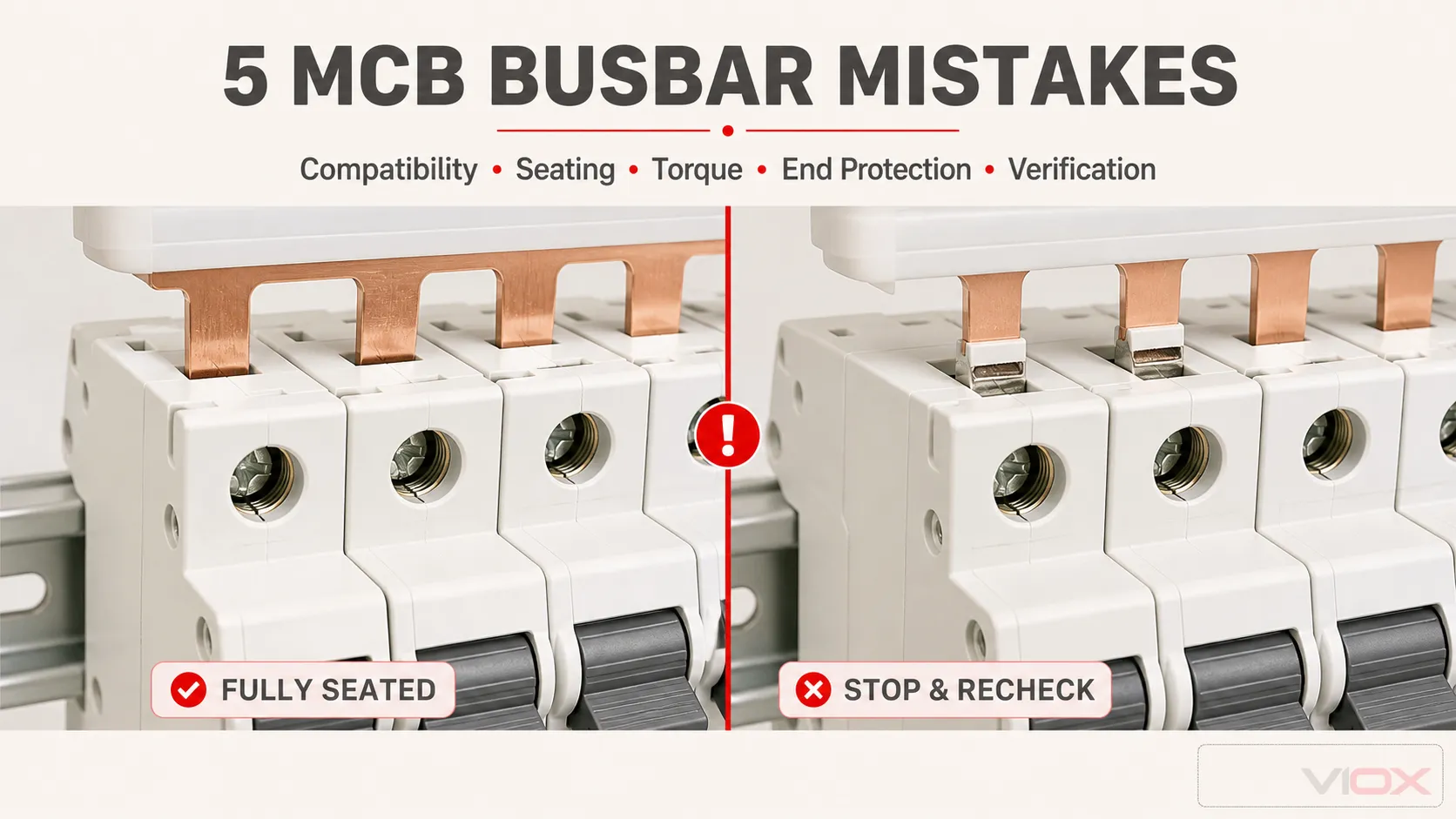
A comb busbar can look aligned from the front while one tooth is outside the clamp, behind the terminal cage, tilted by a misaligned device, or inserted so shallowly that the insulated sleeve is trapped under the pressure point.
Why it fails
The intended connection depends on direct clamping of the conductive tooth in the specified terminal zone. Partial engagement reduces the designed contact interface and can create uneven pressure. A row can also shift during sequential tightening, so a connection that began correctly may no longer be seated as intended when the last terminal is secured.
What to inspect
- Every device is fully seated and latched on the DIN rail before the busbar is tightened.
- Teeth enter the designated terminals without lateral force or visible bending.
- Conductive portions—not insulation—sit in the specified clamp zone.
- The busbar remains straight and the devices remain aligned across the row.
- No copper shaving, burr, loose hardware, or other conductive debris remains in the enclosure.
- Unused teeth are treated with the accessory specified for the busbar system.
Correct action and stop condition
Follow the manufacturer’s installation sequence and inspect every tooth, not just the first and last. If the terminal design prevents a reliable view, use the manufacturer’s stated inspection method; do not infer seating from screw resistance alone. Stop when a tooth needs force, the sleeve is marked or crushed, the row moves out of alignment, or the terminal cannot be inspected as required. Remove and reassess the component combination rather than tightening through a misfit.
Mistake 3: Applying a generic torque—or sharing a terminal without approval
There is no single MCB busbar torque that is valid across all breakers, terminal designs, conductor sizes, and accessories. The correct value and tool come from the exact device instructions. The same restriction applies to placing a supply conductor and a busbar tooth in one terminal: some product systems explicitly provide for a particular arrangement, while others require a feeder terminal or a separate connection method.
Why it fails
Under-tightening can leave inadequate clamping pressure. Over-tightening can damage the screw, clamp, tooth, housing, or conductor. An unapproved shared-terminal arrangement can put two dissimilar conductors in a contact system that was not designed to retain both. None of these defects can be corrected by choosing a breaker B, C, or D trip curve; those curves describe breaker tripping characteristics, not busbar terminal compatibility.
What to inspect
- The tightening value for the exact device terminal and connection arrangement.
- The specified screwdriver or bit profile and, where required, a suitable calibrated torque tool.
- Whether the terminal accepts a busbar tooth, a wire, both together, or a dedicated feeder accessory.
- Permitted conductor type, size, preparation, and insertion length for the chosen feed method.
- The manufacturer’s tightening order and any re-check required by the assembly procedure.
Correct action and stop condition
Record the source document and value in the job or panel documentation, then apply the specified method. Stop if the model cannot be identified, the terminal diagram is ambiguous, a fastener does not tighten normally, or the required connection arrangement is absent from the documentation. Do not substitute a value copied from a different MCB family, a general internet range, or personal feel.
For the complete breaker procedure—including line/load identification, conductor preparation, and verification—use the MCB installation guide. This page remains focused on the comb-busbar failure points.
Mistake 4: Cutting a non-cuttable busbar or leaving the end unprotected
Some comb busbars are supplied for field cutting with a defined method and matching end accessories; others are pre-assembled or product-specific and should not be cut. Even where cutting is allowed, the tooth count, phase sequence, square cut, debris removal, insulation clearance, and end treatment must all remain correct.
Why it fails
An uncontrolled cut can damage insulation, deform conductors, change the intended phase sequence, leave conductive debris in the board, or expose live metal at the end. Tape or improvised heat-shrink is not automatically equivalent to the manufacturer’s end cap or approved finishing system.
What to inspect
- The exact busbar instructions explicitly allow field cutting.
- The measured cut position preserves the required tooth and phase sequence.
- The specified tool and restraint method will not crush the sleeve or bend the teeth.
- The cut face is clean and free from burrs and conductive debris.
- The matching end cap and any unused-tooth covers are present and fully seated.
- Required clearances and enclosure barriers remain intact after modification.
Correct action and stop condition
Use only the documented method and accessories for the exact busbar. If cutting permission or end treatment cannot be verified, obtain the correct length instead. The comb busbar cutting and insulation guide covers the full controlled procedure; do not improvise from this summary.
Stop and replace the part if a conductor is nicked, a tooth is loosened or bent, the sleeve is cracked or crushed, debris cannot be confidently removed, or the specified end protection cannot be fitted.
Mistake 5: Treating “power off” as proof that the assembly is safe and complete
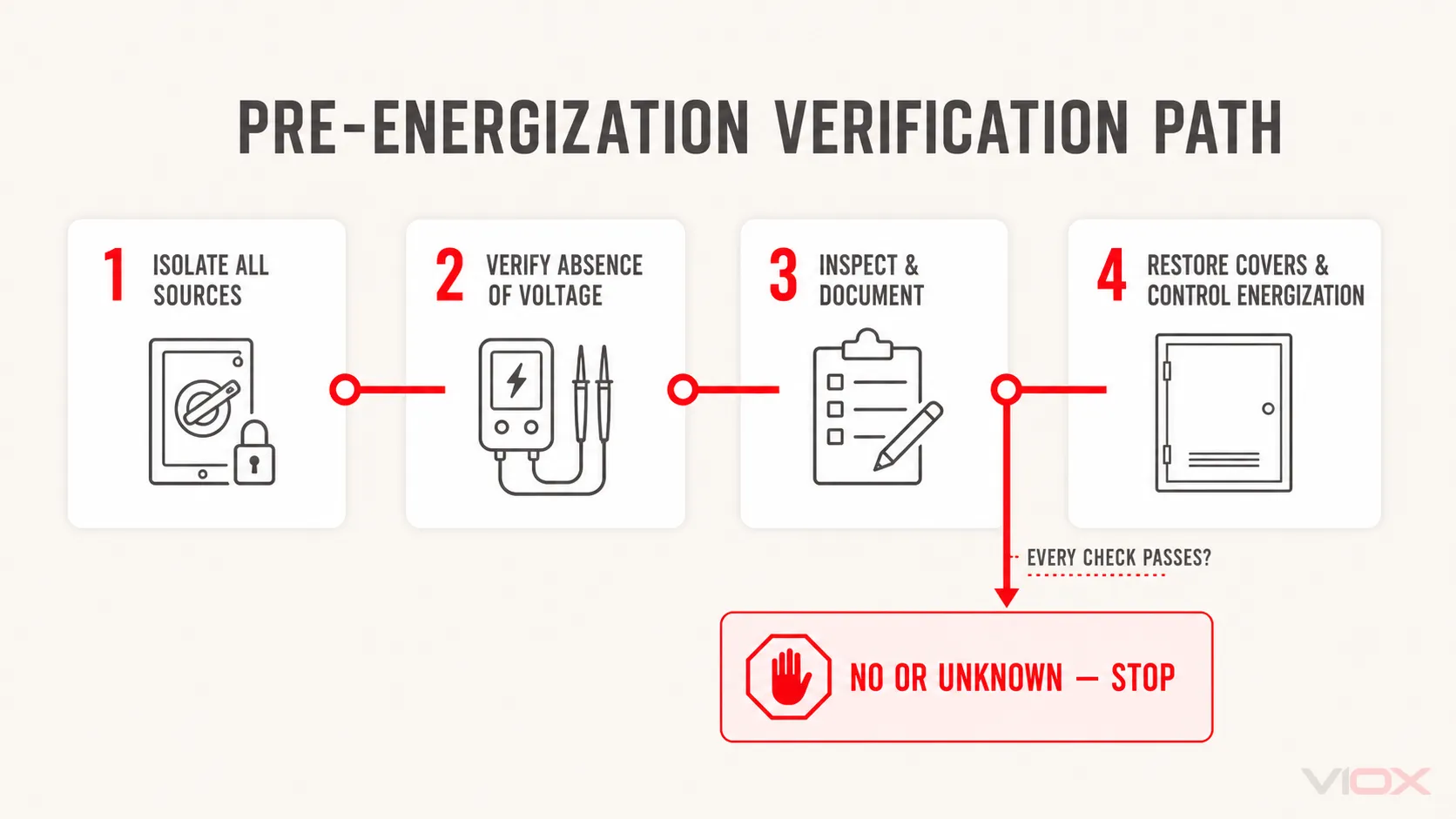
Operating a main switch is not, by itself, a complete isolation and verification process. The safe-work method must account for all possible sources, control unexpected re-energization, and verify absence of voltage with suitable test equipment at the relevant exposed parts. The applicable site procedure and local law determine the exact steps and who may perform them.
Why it fails
A board may have an alternate supply, backfeed, incorrect labeling, a divided busbar section, stored energy, or a device that does not isolate the expected conductors. After assembly, a neat visual appearance also does not prove correct phase sequence, correct terminal engagement, secure accessories, or suitability for energization.
What to inspect before work and before restoration
- All identified energy sources are disconnected and controlled under the site isolation procedure.
- Absence of voltage is verified by a qualified person with suitable test equipment using the required proving method.
- Product codes, row schedule, phase arrangement, feed location, and terminal assignments match the design documents.
- Every tooth, terminal, end cap, tooth cap, barrier, cover, label, and unused opening passes visual inspection.
- Tightening completion is documented according to the manufacturer and site quality process.
- Tools, loose parts, offcuts, and conductive debris have been removed.
- Enclosure covers and protective barriers are restored before the controlled energization and commissioning process.
Correct action and stop condition
Use a written isolation and pre-energization checklist. Stop when there is an unidentified source, an unverified test point, a missing barrier, damaged insulation, uncertain phase order, an undocumented connection, or an abnormal mechanical result. Escalate to the responsible qualified person or panel designer rather than energizing to “see if it works.”
If the installation later shows discoloration, odor, nuisance operation, or a suspected hot connection, isolate it and follow the MCB busbar overheating diagnostic guide. A symptom-led inspection is a separate task from the preventive checks on this page.
Pre-energization acceptance checklist
Use this final gate only after the exact manufacturer instructions and the applicable site procedure have been reviewed.
One failed or unknown item is a stop result, not a minor exception.
Technical references
- ABB, Accessories for MCBs and RCDs: product-family, terminal, pole, module, current-capacity, accessory, and cuttable/non-cuttable selection distinctions.
- Schneider Electric, Resi9 Comb Busbar instruction sheet: model-specific comb-busbar installation documentation.
- OSHA interpretation on de-energized electrical work: general U.S. guidance on disconnecting, lockout/tagout, qualified-person testing, and verification of de-energization. Local rules may differ and remain controlling.
For product comparison after the row requirements are known, review the VIOX MCB busbar range. The installation decision must still be based on the exact product documentation and the complete assembly design.