On this page
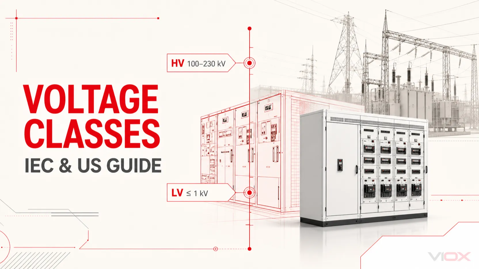
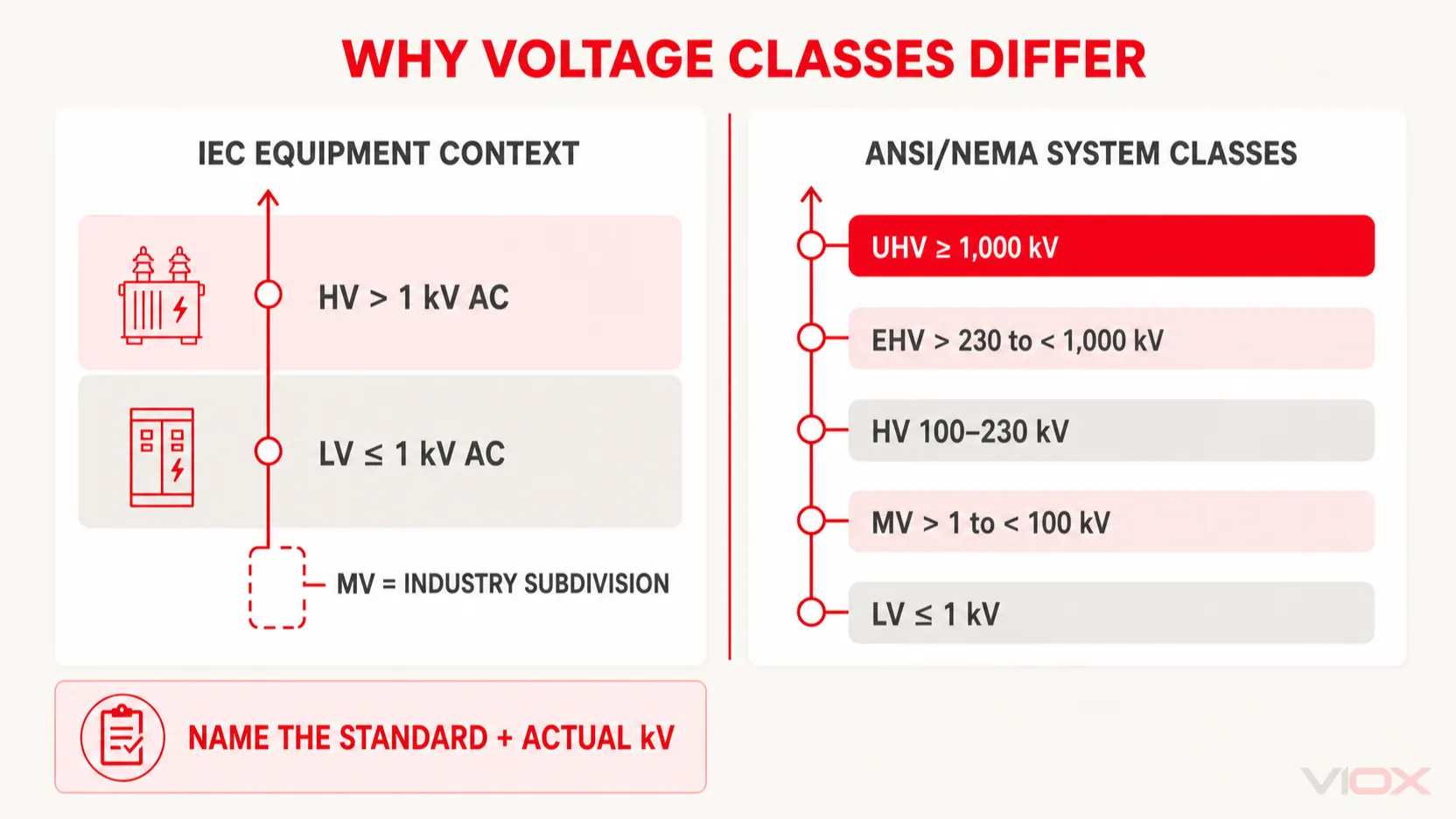
Low, medium and high voltage do not have one universal set of boundaries. In the broad IEC equipment context, low voltage extends to 1,000 V AC or 1,500 V DC; voltages above that boundary fall within the high-voltage domain, where “medium voltage” is widely used as an industry subdivision. In North American system-voltage terminology, ANSI/NEMA C84.1 classifies low voltage as 1 kV or less, medium voltage as above 1 kV and below 100 kV, and high voltage as 100–230 kV.
That difference explains why a 13.8 kV system can be called medium voltage in a plant but still be covered by an IEC standard whose title says “high-voltage switchgear.” For any design, quotation or specification, state the actual nominal voltage, AC or DC, and the governing standard instead of relying on LV, MV or HV alone.
| Classification context | Low voltage (LV) | Medium voltage (MV) | High voltage (HV) | Extra-high / ultra-high voltage |
|---|---|---|---|---|
| IEC equipment boundary | Up to 1 kV AC or 1.5 kV DC | Common industry subdivision above LV; upper limit depends on sector and equipment standard | Broadly, voltage above LV; may include MV, EHV and UHV | Terms and boundaries depend on the application standard or network operator |
| ANSI/NEMA C84.1 system-voltage classes | 1 kV or less | Above 1 kV and below 100 kV | 100 kV to 230 kV | EHV: above 230 kV and below 1,000 kV; UHV: 1,000 kV or more |
| Common IEC-oriented network usage | Up to 1 kV | Often above 1 kV to 35 kV or 52 kV | Often above the local MV ceiling | Varies by country, utility and transmission standard |
The third row is a practical convention, not a universal IEC classification table. Always check the cited project standard.
What Is Voltage and Why Classification Matters
Voltage is electric potential difference—the driving force that can produce current through a circuit. It is measured in volts (V), while kilovolts (kV) represent 1,000 volts.
Voltage classification matters because it affects:
- equipment insulation level and clearances;
- switchgear, cable and transformer ratings;
- protection and grounding design;
- installation and test procedures;
- worker qualification and safe-work controls; and
- utility interconnection and regulatory requirements.
A voltage-class label is only a starting point. Equipment selection still depends on nominal and maximum system voltage, frequency, AC or DC, grounding method, prospective fault current, insulation coordination, environment and the applicable product standard.
International Standards for Voltage Classification
IEC Standards
IEC 60038 specifies preferred nominal voltage values for supply systems and reference values for equipment and system design. It should not be cited as if it creates one universal LV/MV/HV/EHV/UHV classification table.
IEC 61140 establishes common principles for protection against electric shock. In IEC equipment practice, 1,000 V AC and 1,500 V DC are important upper boundaries for low voltage. Above that boundary, IEC documents can use “high voltage” as a broad equipment category. For example, IEC 62271-1 applies to AC high-voltage switchgear and controlgear rated above 1,000 V—even though much of that equipment is called medium voltage in everyday distribution engineering.
Therefore, the safest IEC wording is:
- LV: up to 1 kV AC or 1.5 kV DC in the relevant equipment context;
- MV: a widely used industry term for the lower part of the above-LV range, commonly associated with distribution equipment;
- HV: the broad IEC domain above LV, or a narrower utility category where the local network standard defines one;
- EHV/UHV: transmission terms whose exact thresholds must be stated from the governing standard or utility specification.
ANSI/NEMA and NEC Context
For 60 Hz power systems, ANSI/NEMA C84.1-2020 (R2025) provides a useful North American system-voltage classification:
- Low voltage: 1 kV or less;
- Medium voltage: above 1 kV and below 100 kV;
- High voltage: 100 kV to 230 kV;
- Extra-high voltage: above 230 kV and below 1,000 kV;
- Ultra-high voltage: 1,000 kV or more.
These are nominal system-voltage classes. They are not a substitute for the National Electrical Code (NEC), a product standard, an OSHA work rule or a utility specification. The NEC often organizes requirements around explicit voltage thresholds, so write “13.8 kV system” or “480 V circuit” wherever precision matters.
Why the Definitions Appear to Conflict
The terms describe different things in different documents. One standard may classify an entire power system, another may define the scope of switchgear, and a safety rule may use a voltage threshold to trigger a work practice. A circuit can therefore be:
- medium voltage in plant-distribution language;
- within the IEC high-voltage switchgear family; and
- subject to a separate safety threshold under local law.
This is not necessarily a contradiction. It is a reason to identify the document, edition, nominal voltage and equipment type.
Low Voltage (LV) Systems
Definition and Range
In common IEC equipment usage, low voltage is up to 1,000 V AC or 1,500 V DC. ANSI/NEMA C84.1 also places nominal AC systems of 1 kV or less in the low-voltage class.
Do not confuse this engineering meaning with informal phrases such as “low-voltage controls,” which may refer to 12 V, 24 V or 48 V circuits. Extra-low-voltage and limited-energy circuits have their own definitions and requirements.
Characteristics
LV systems are the final distribution and utilization level for most buildings and many machines. Equipment is widely available, but the label “low voltage” does not mean low risk. A 480 V switchboard can have substantial shock and arc-flash hazards.
Common Applications
- 120/240 V residential systems in North America;
- 230/400 V building systems in many IEC markets;
- 400 V, 480 V, 600 V and 690 V industrial distribution;
- machine power and control circuits;
- low-voltage DC systems within the relevant rating limits.
Typical Equipment
LV assemblies may include miniature circuit breakers, molded-case circuit breakers, contactors, distribution boards, disconnectors, surge protective devices and power distribution blocks. Verify each device's operational voltage, insulation voltage, interrupting rating and applicable standard.
Safety Considerations
Use an electrically safe work condition whenever required and feasible. Shock protection, arc-flash controls and PPE are based on the actual exposure and task—not on the reassuring sound of “low voltage.”
Medium Voltage (MV) Systems
Definition and Range
Medium voltage is a practical power-distribution category above low voltage. ANSI/NEMA C84.1 defines MV nominal systems as above 1 kV and below 100 kV. In IEC-oriented distribution practice, MV commonly refers to systems above 1 kV up to 35 kV or 52 kV, but the upper limit varies by country, utility and equipment family.
Always specify the actual level—for example, 3.3 kV, 6.6 kV, 11 kV, 13.8 kV, 22 kV or 33 kV—rather than ordering “MV equipment” without a rating.
Characteristics
MV distribution reduces current for a given power transfer compared with LV. It also requires purpose-designed insulation, switching, protection, cable terminations, grounding and test procedures. System grounding and fault-clearing strategy materially affect equipment and protection choices.
Common Applications
- utility primary distribution;
- industrial plant substations and feeders;
- large motors and process loads where the engineered system justifies MV;
- renewable generation collection systems;
- campus, airport, mine and data-center distribution networks.
Typical Equipment
Typical equipment includes metal-enclosed switchgear, circuit breakers or contactors within their published scope, protection relays, instrument transformers, MV cables and terminations, transformers and grounding equipment. IEC 62271-200, for example, covers certain AC metal-enclosed assemblies rated above 1 kV up to and including 52 kV.
Safety Considerations
MV work requires qualified personnel, controlled access, an approved switching or test procedure, verified isolation and grounding where required. Approach boundaries, test-instrument ratings, temporary grounds and PPE must come from the applicable rules and the task-specific risk assessment.
High Voltage (HV) Systems
Definition and Range
What is considered high voltage? The correct answer depends on context. In broad IEC equipment terminology, voltage above 1 kV AC or 1.5 kV DC is in the high-voltage domain. In ANSI/NEMA C84.1 system classes, HV means 100–230 kV. Utilities may use another local boundary between medium- and high-voltage networks.
This is why the phrase “high voltage starts at 35 kV” can be useful in one network but wrong as a universal statement.
Characteristics
HV systems enable bulk power transfer at lower current than a lower-voltage system carrying the same power. Design priorities include insulation coordination, switching overvoltages, clearances, protection, line or cable characteristics, substation layout and system stability.
Common Applications
- regional and long-distance transmission;
- transmission substations and grid interconnections;
- connection of large generation sources;
- high-capacity utility supply corridors.
Typical Equipment
HV installations use application-specific power transformers, circuit breakers, disconnectors, instrument transformers, surge arresters, bus systems, overhead lines or HV cables, protection relays and control systems. Technology may be air-, gas-, oil-, vacuum- or solid-insulated depending on voltage, duty and product design; the voltage class alone does not select the interruption or insulation medium.
Safety Considerations
HV work depends on formal operating authority, isolation, verification, grounding, minimum approach distances and specialized training. Remote operation may reduce exposure in some tasks, but it does not replace a documented hazard assessment and approved procedure.
Extra High Voltage (EHV) and Ultra High Voltage (UHV)
Under ANSI/NEMA C84.1 system classes, EHV is above 230 kV and below 1,000 kV, while UHV is 1,000 kV or more. International transmission usage is not uniform: some networks use different AC thresholds, and DC projects are often described by their stated pole-to-pole or pole-to-ground voltage rather than by a universal EHV/UHV table.
EHV and UHV systems are used for bulk transmission where the network study justifies the infrastructure, insulation, right-of-way, reactive-power control and station complexity. Always retain the actual kV value alongside the acronym.
Comparative Analysis: LV vs. MV vs. HV
| Factor | Low voltage | Medium voltage | High voltage |
|---|---|---|---|
| Working definition | Up to 1 kV AC / 1.5 kV DC in common IEC equipment usage | Above LV; distribution range defined by the relevant market or equipment standard | Broadly above LV in IEC equipment language; 100–230 kV under ANSI/NEMA C84.1 |
| Typical role | Final distribution and utilization | Primary distribution and large-site networks | Bulk power transmission and major interconnection |
| Current for equal three-phase power | Highest | Lower | Lowest |
| Equipment | LV boards, breakers, contactors and final circuits | MV switchgear, relays, cables and transformers | Transmission switchyards, power transformers, lines/cables and protection systems |
| Design emphasis | Final-circuit protection, utilization and panel integration | Insulation, grounding, protection coordination and maintainability | Insulation coordination, system studies, switching duties and grid performance |
| Terminology risk | “Low” may be mistaken for harmless | Upper limit varies widely | IEC equipment and utility-network meanings differ |
Power Loss Comparison
Conductor loss is:
P_loss = I²RFor balanced three-phase power:
P = √3 × V_LL × I × power factorIf transferred power and power factor stay constant, increasing line-to-line voltage by a factor of 10 reduces current to one-tenth. If conductor resistance is also held constant for comparison, I²R loss becomes one-hundredth—a 99% reduction.
This proportional example explains the benefit of higher transmission voltage, but it is not a complete line design. Real losses also depend on conductor size and length, resistance, reactive power, corona, cables or overhead-line geometry, transformers and operating conditions.
Selecting the Right Voltage Level for Your Application
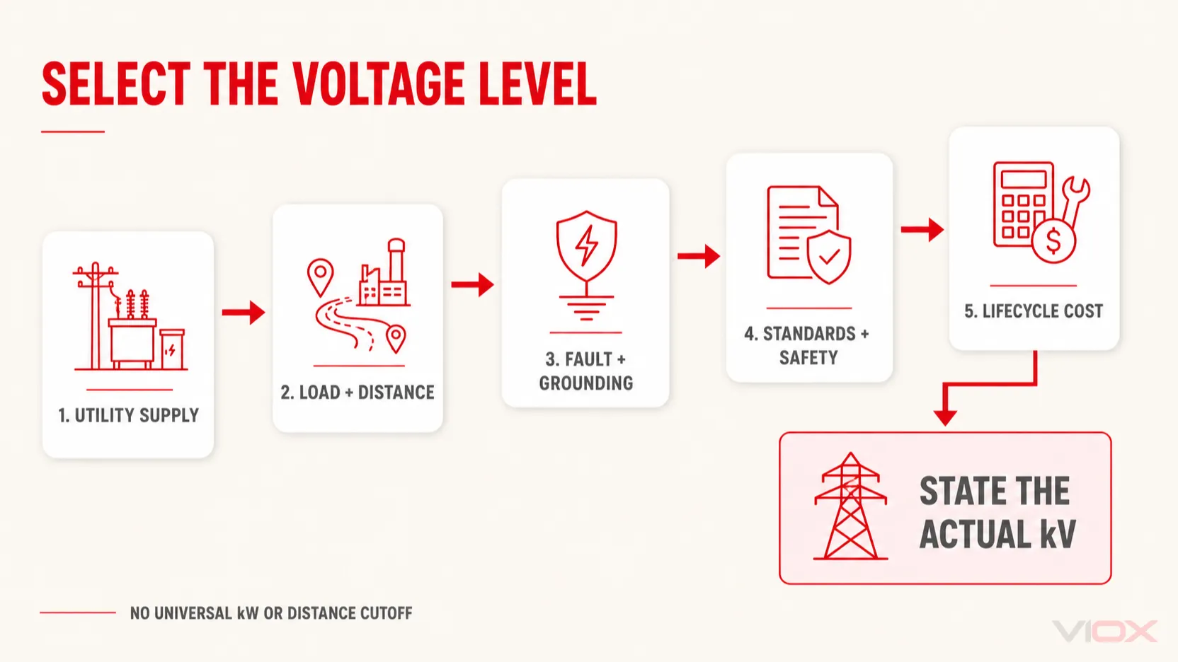
Do not choose LV, MV or HV from a universal power or distance cutoff. The economic transition point changes with the utility supply, load profile, conductor route, equipment availability, reliability target and local rules.
1. Power Requirements
Calculate maximum demand, diversity, load growth, starting current and power quality. Compare current, voltage drop, cable count and equipment ratings at each feasible voltage.
2. Distribution Distance
Model voltage drop, conductor loss, route constraints and installation cost. A long feeder or concentrated load can favor a higher distribution voltage, but distance alone does not decide.
3. Load Type
Identify motors, transformers, converters, heating, lighting and nonlinear loads. A large motor is not automatically an MV motor; system voltage, starting method, process duty, availability and total life-cycle cost govern the choice.
4. Cost Considerations
Compare utility connection charges, transformers, switchgear, cables, protection, civil works, commissioning, spare parts, training, maintenance and energy losses. The lowest equipment price may not produce the lowest total cost.
5. Safety and Regulatory Requirements
Map the applicable installation code, equipment standards, utility rules, worker-safety regulations and inspection requirements. Confirm short-circuit ratings, grounding, protection coordination and safe operating procedures.
6. Future Expansion
Reserve realistic feeder, transformer and switchgear capacity; verify whether the chosen architecture can accept future loads without exceeding fault-duty, thermal or space limits.
For a real project, document the decision in a one-line design basis such as: “13.8 kV, 60 Hz, resistance-grounded primary distribution; ANSI/IEEE equipment basis; final ratings subject to utility fault data and coordination study.”
Voltage Transformation and Distribution Networks
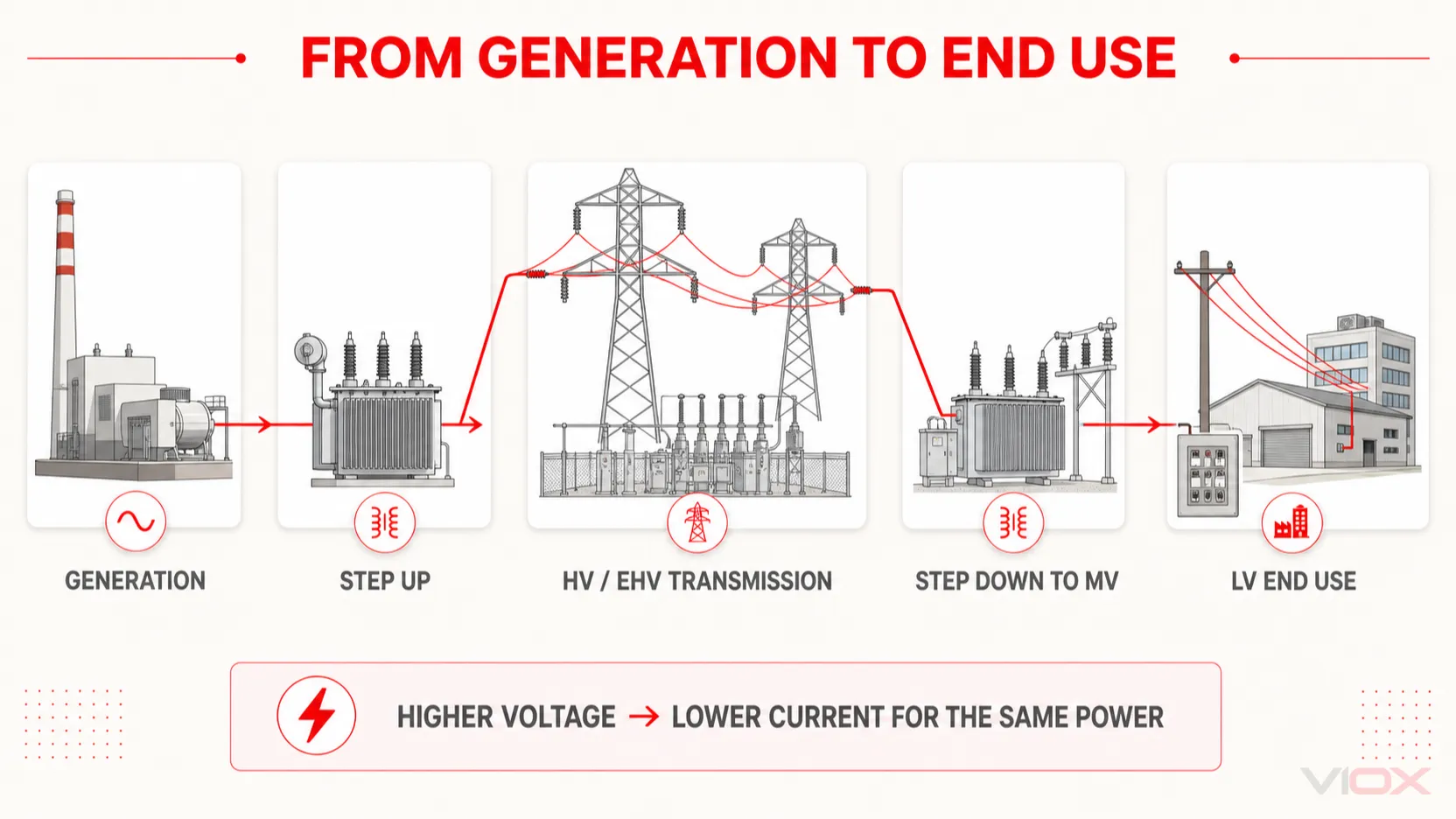
A typical grid uses several coordinated voltage levels:
- Generators produce power at a design-specific voltage.
- A step-up transformer raises voltage for transmission.
- Transmission networks move bulk power at HV, EHV or UHV.
- Grid substations step down to subtransmission or primary distribution voltage.
- Distribution substations transform MV to LV.
- LV systems supply buildings, machines and final circuits.
The exact sequence varies. Industrial sites, renewable plants and data centers may take utility service at MV or HV and perform additional transformation onsite. See the VIOX comparison of dry-type and oil-filled transformers for one equipment-level decision within this architecture.
Safety Standards and Compliance
International Standards
Relevant documents may include:
- IEC 60364 series for low-voltage electrical installations;
- IEC 62271 series for high-voltage switchgear and controlgear within each part's scope;
- IEC 61140 for common electric-shock protection principles;
- IEEE C37 series for applicable switchgear and protection equipment;
- NFPA 70 (NEC) for electrical installations in jurisdictions that adopt it; and
- NFPA 70E and applicable OSHA rules for workplace electrical safety in the United States.
A standard family name is not enough. Verify the applicable part, edition, equipment scope and local adoption.
Personal Protective Equipment (PPE)
PPE cannot be selected from voltage class alone. Shock protection depends on nominal voltage, exposure and approach boundaries; arc-rated clothing depends on the task and estimated incident energy or a permitted table method. Gloves, instruments and tools also need suitable voltage and category ratings.
The hierarchy begins with eliminating exposure by establishing an electrically safe work condition where required. PPE is a final protective layer, not permission to work energized.
Arc Flash Hazard Analysis
Do not assume that every circuit above 50 V automatically requires the same arc-flash study or fixed PPE level. Arc-flash energy depends strongly on available fault current, protective-device clearing time, equipment configuration and working distance—not voltage alone. Follow the applicable NFPA 70E method, OSHA rule, local regulation and site electrical-safety program.
For labeling details, see the VIOX guide to NEC and NFPA 70E arc-flash labels. OSHA also notes that arc-flash incident energy depends primarily on current, clearing time and working distance in its electric-arc flash hazard guidance.
Emerging Trends in Voltage Technology
HVDC (High-Voltage Direct Current)
HVDC can be attractive for selected long-distance, submarine, asynchronous-interconnection and renewable-energy projects. Its value must be established by a system and economic study; there is no universal distance at which HVDC automatically becomes superior.
Smart Grid Integration
Digital relays, sensors, condition monitoring and automated voltage regulation improve observability across LV, MV and HV networks. Their communication and cybersecurity functions complement—but do not replace—primary protection and physical ratings.
Renewable Energy Considerations
Solar, wind and energy-storage projects may combine DC collection, inverter output, MV collection and HV interconnection. Each interface needs coordinated insulation, grounding, surge protection, fault detection and utility compliance. Use the actual AC and DC ratings instead of transferring a classification from one side of the converter to the other.
Key Takeaways
- There is no universal low, medium and high voltage range table.
- In common IEC equipment usage, LV extends to 1 kV AC or 1.5 kV DC; above that is the broad high-voltage domain.
- ANSI/NEMA C84.1 classifies nominal AC systems as LV at 1 kV or less, MV above 1 kV and below 100 kV, and HV from 100 kV to 230 kV.
- IEC “high-voltage switchgear” can include equipment commonly called MV in distribution practice.
- State the actual nominal voltage, AC or DC, grounding method and governing standard.
- Higher voltage reduces current for the same transferred power, but voltage-level selection requires a full technical and economic study.
- Safety controls and PPE come from the task and hazard assessment, not the LV/MV/HV label alone.
Short FAQ Section
What is the main difference between low, medium and high voltage?
The main difference is the system or equipment context in which the voltage is used. LV generally serves final distribution and utilization, MV serves primary distribution and large sites, and HV serves bulk transmission. Exact numerical boundaries depend on the governing standard.
What is considered high voltage?
In broad IEC equipment terminology, voltage above 1 kV AC or 1.5 kV DC is high voltage and can include the industry subdivision called medium voltage. Under ANSI/NEMA C84.1, the high-voltage system class is 100–230 kV. Always name the context.
Is 480 V considered low or medium voltage?
480 V is low voltage under both the common IEC equipment boundary and ANSI/NEMA C84.1. It can still present serious shock and arc-flash hazards, so “low voltage” must not be read as “low risk.”
What is the medium voltage range in the United States?
ANSI/NEMA C84.1 defines medium-voltage nominal systems as above 1 kV and below 100 kV. Individual equipment standards cover narrower rating ranges; for example, common metal-clad distribution switchgear ratings do not span that entire class.
What is the extra-high voltage range?
ANSI/NEMA C84.1 defines EHV as above 230 kV and below 1,000 kV. International utility terminology varies, so the standard or network convention must be stated.
Why do IEC voltage levels appear different from utility terminology?
IEC documents often define equipment scope, while utilities use operational network categories. As a result, 11 kV or 33 kV equipment may be called MV by a utility but fall within an IEC high-voltage switchgear standard.
How should an industrial facility choose between low and medium voltage?
Compare utility service, demand, feeder current, voltage drop, cable routes, fault duty, equipment cost, reliability, maintenance capability and expansion. There is no universal kW, motor-horsepower or distance threshold that replaces an engineered study.
Conclusion
Voltage classification is useful only when its context is explicit. Use LV, MV, HV, EHV and UHV as navigation terms, then anchor every design and purchase decision to the actual nominal and maximum voltage, AC or DC, grounding system, equipment standard and local requirements.
For global projects, the most important distinction is that IEC high-voltage equipment scope begins above the low-voltage boundary, while ANSI/NEMA system classes reserve “high voltage” for 100–230 kV. Writing the kV value next to the class prevents that difference from becoming a specification error.
VIOX supplies electrical components for low-voltage distribution and selected power-distribution applications. Product suitability must be confirmed from model-specific ratings, certificates and project requirements. For assistance, contact VIOX.
Sources
- IEC 60038:2009+AMD1:2021 — IEC standard voltages
- IEC 61140:2016 — Protection against electric shock
- IEC Guide 111-1:2023 — AC equipment for high-voltage substations
- IEC 62271-1:2017+AMD1:2021 — High-voltage switchgear and controlgear
- ANSI/NEMA C84.1-2020 (R2025) — NEMA standards plan
- OSHA — Electric-arc flash hazards