នៅលើទំព័រនេះ
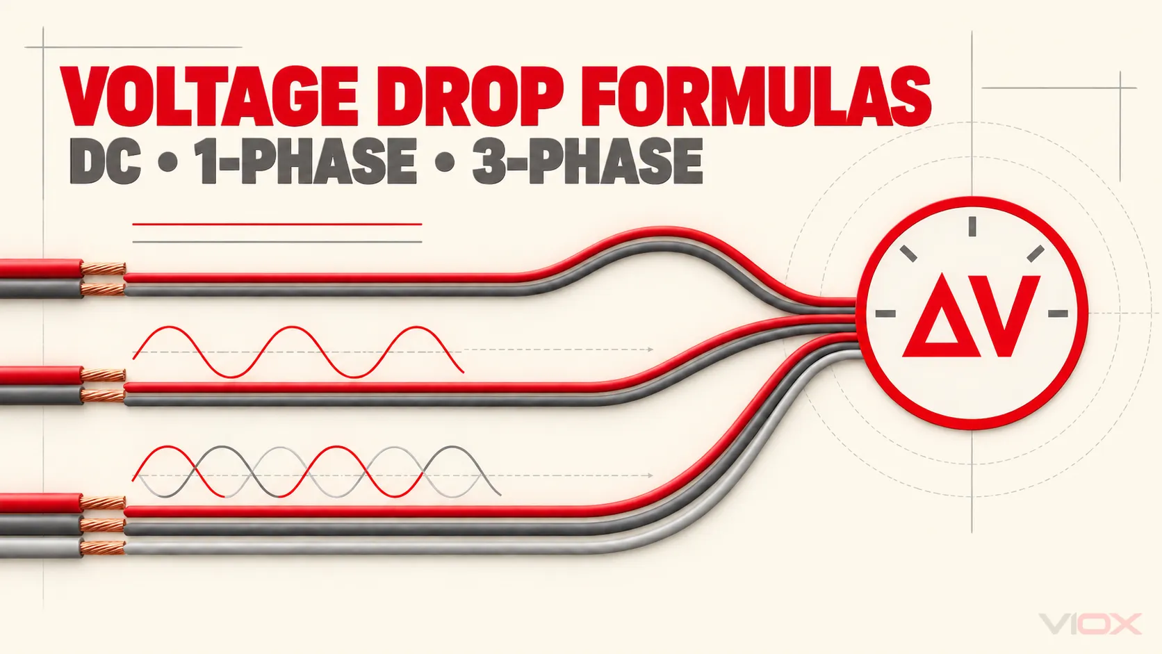
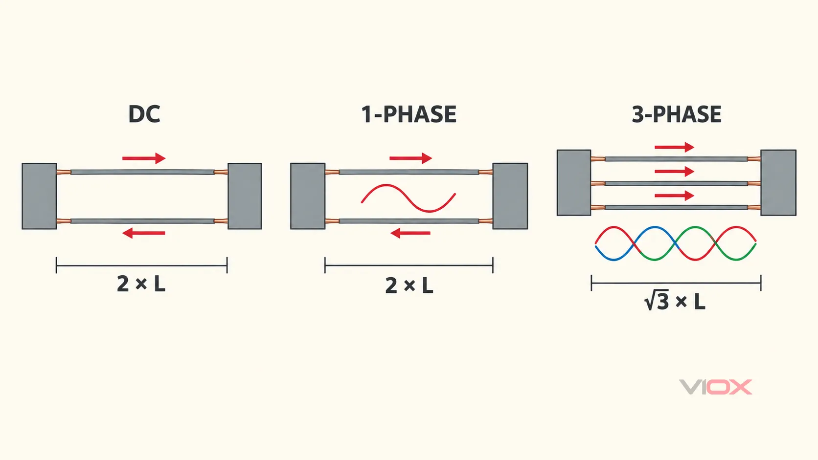
ការធ្លាក់ចុះតង់ស្យុង គឺជាភាពខុសគ្នារវាងតង់ស្យុងនៅប្រភព និងតង់ស្យុងដែលមាននៅបន្ទុក ខណៈពេលដែលចរន្តកំពុងហូរ។ សម្រាប់សៀគ្វី DC ខ្សែពីរ សូមប្រើ 2LIR ពេលណា អិល គឺជាប្រវែងផ្លូវតែមួយ និង រ គឺជាភាពធន់នៃខ្សែចំលងមួយក្នុងមួយឯកតាប្រវែង។ សម្រាប់ AC ហ្វាសតែមួយ សូមគិតបញ្ចូលទាំងភាពធន់ ភាពប្រតិកម្ម និងកត្តាថាមពល។ សម្រាប់សៀគ្វីបីហ្វាសដែលមានតុល្យភាព សូមជំនួសកត្តា 2 ជាមួយ sqrt(3).
| សៀគ្វី | រូបមន្តធ្លាក់ចុះតង់ស្យុងក្នុងស្ថានភាពនឹងនរ | តង់ស្យុងដែលប្រើសម្រាប់ភាគរយនៃការធ្លាក់ចុះ |
|---|---|---|
| DC ខ្សែពីរ | Delta V = 2 x L x I x R |
តង់ស្យុងប្រព័ន្ធ DC |
| AC ហ្វាសតែមួយខ្សែពីរ | Delta V = 2 x L x I x (R x cos phi + X x sin phi) |
វ៉ុលរវាងខ្សែនិងខ្សែ ឬរវាងខ្សែនិងខ្សែអព្យាក្រឹតរបស់សៀគ្វី តាមការអនុវត្តជាក់ស្តែង |
| AC បីហ្វាមានតុល្យភាព | Delta V_LL = sqrt(3) x L x I x (R x cos phi + X x sin phi) |
វ៉ុលរវាងខ្សែនិងខ្សែ |
បន្ទាប់មកធ្វើការគណនា៖
ការធ្លាក់ចុះវ៉ុល (%) = 100 x Delta V / វ៉ុលសៀគ្វីនាមករណ៍
រូបមន្តទាំងនេះមានសុពលភាពតែនៅពេលដែលឯកតានានាត្រូវគ្នា។ ប្រសិនបើ រ និង X មានឯកតាជាអូមក្នុងមួយគីឡូម៉ែត្រ សូមបញ្ចូល អិល ជាគីឡូម៉ែត្រ។ ប្រសិនបើវាមានឯកតាជាអូមក្នុងមួយ 1,000 ហ្វីត សូមបញ្ចូលប្រវែងផ្លូវតែមួយជាប្រភាគនៃ 1,000 ហ្វីត។.
កន្សោម AC ដែលបង្ហាញនៅទីនេះប្រើទម្រង់ប្រហាក់ប្រហែលធម្មតាសម្រាប់ យឺត កត្តាថាមពលផ្ទុក។ សៀគ្វីដែលមានកត្តាថាមពលនាំមុខអាចផ្លាស់ប្តូរនិមិត្តសញ្ញានៃកន្សោមប្រតិកម្ម; សូមប្រើគំរូហ្វាស័រ (phasor model) ដែលអាចអនុវត្តបាន ជំនួសឱ្យការចម្លងរូបមន្តផ្ទុកយឺតដោយមិនកែប្រែ។.
សម្រាប់លទ្ធផលបឋមរហ័ស សូមប្រើ ម៉ាស៊ីនគណនាការធ្លាក់ចុះតង់ស្យុង VIOX. វិធីសាស្ត្រដោយដៃខាងក្រោមបង្ហាញពីអត្ថន័យនៃទិន្នន័យបញ្ចូលរបស់ម៉ាស៊ីនគិតលេខ និងពេលណាដែលការសិក្សាវិស្វកម្មលម្អិតបន្ថែមទៀតមានភាពចាំបាច់។.
អថេរ និងឯកតា
| និមិត្តសញ្ញា | អត្ថន័យ | ប្រើវាឱ្យបានត្រឹមត្រូវ |
|---|---|---|
Delta V |
ការធ្លាក់ចុះតង់ស្យុងដែលបានគណនា ជាវ៉ុល | ប្រៀបធៀបវាជាមួយនឹងតង់ស្យុងនៅលើមូលដ្ឋានសៀគ្វីតែមួយ |
អិល |
ប្រវែងផ្លូវតែមួយទិស | កុំគុណនឹងពីរមុនពេលប្រើរូបមន្តដែលមានស្រាប់ 2 |
ខ្ញុំ |
ចរន្តផ្ទុកគិតជាអំពែរ | ប្រើចរន្តនៅក្នុងផ្នែកដែលកំពុងគណនា |
រ |
ភាពធន់របស់ចំហាយ AC ឬ DC ក្នុងមួយឯកតានៃប្រវែង | ប្រើទិន្នន័យសម្រាប់សម្ភារៈចំហាយ ទំហំ ការសាងសង់ និងសីតុណ្ហភាពប្រតិបត្តិការដែលពាក់ព័ន្ធ |
X |
ប្រតិកម្មចំហាយក្នុងមួយឯកតានៃប្រវែង | ប្រើទិន្នន័យខ្សែ ឬទិន្នន័យដំឡើងសម្រាប់ការរៀបចំចំហាយជាក់ស្តែង |
cos phi |
កត្តាថាមពលនៃការផ្លាស់ទី (Displacement power factor) | កុំជំនួសប្រសិទ្ធភាព ឬកម្រិតបង្ខូចសញ្ញាអាម៉ូនិកសរុប (total harmonic distortion) |
sin phi |
sqrt(1 - cos^2 phi) សម្រាប់បន្ទុកដែលមានភាពយឺតយ៉ាវនៃរលកស៊ីនុសដែលបានសន្មត |
វាបង្ហាញពីសមាសភាគប្រតិកម្មនៅក្នុងរូបមន្ត AC ប៉ាន់ស្មាន; កត្តាថាមពលនាំមុខតម្រូវឱ្យមានការកំណត់សញ្ញាឱ្យបានត្រឹមត្រូវ |
អនុសញ្ញាប្រវែងផ្លូវតែមួយគឺជាប្រភពទូទៅបំផុតនៃកំហុសក្នុងការគណនា។ សៀគ្វី DC ឬសៀគ្វីហ្វាសតែមួយដែលមានខ្សែពីរ មានខ្សែបញ្ជូនចេញ និងខ្សែត្រឡប់មកវិញ ដូច្នេះរូបមន្តគុណប្រវែងផ្លូវតែមួយនឹង 2. ការគណនាប្រព័ន្ធបីហ្វាសដែលមានតុល្យភាពប្រើទំនាក់ទំនងហ្វាសរវាងខ្សែបញ្ជូន ដែលបង្កើតបានជា sqrt(3) កត្តាជំនួសវិញ។.
ប្រសិនបើតារាងខ្សែភ្លើងបានផ្តល់រួចហើយនូវ ភាពធន់នៃរង្វិលជុំ, កុំគុណនឹង 2 ម្តងទៀត។ សូមបញ្ជាក់ថាតើតម្លៃដែលបានចុះផ្សាយនោះគឺសម្រាប់ខ្សែនីមួយៗ សម្រាប់មួយគូ សម្រាប់មួយគីឡូម៉ែត្រ ឬសម្រាប់ 1,000 ហ្វីត មុនពេលធ្វើការគណនា។.
មូលហេតុដែលភាពធន់តែមួយមុខមិនគ្រប់គ្រាន់ជានិច្ច
សម្រាប់សៀគ្វី DC ដែលមានភាពធន់សុទ្ធ ការធ្លាក់ចុះតង់ស្យុងអនុវត្តតាមច្បាប់របស់ Ohm៖
Delta V = I x R_loop
សម្រាប់សៀគ្វី AC ភាពស្ទាក់ស្ទើរនៃខ្សែចំលងមានទាំងភាពធន់ និងភាពប្រតិកម្ម។ ការប៉ាន់ប្រមាណស្ថានភាពស្ថិរភាពទូទៅគឺ៖
Delta V = I x (R x cos phi + X x sin phi) x កត្តាដំណាក់កាលនិងប្រវែង
នេះ។ R cos phi គឺជាតំណាងនៃសមាសភាគដែលមានដំណាក់កាលដូចគ្នា។ ចំណែកឯ X sin phi គឺជាតំណាងនៃសមាសភាគតង់ស្យុងដែលទាក់ទងនឹងប្រតិកម្មនៃចំហាយអគ្គិសនី និងកត្តាថាមពលនៃបន្ទុក។ Seattle Public Utilities បានបង្ហាញពីការប៉ាន់ប្រមាណនេះ និងអនុវត្តកត្តា 2 សម្រាប់សៀគ្វីដែលមានដំណាក់កាលតែមួយ (single-phase) និងប្រហែល 1.73 សម្រាប់សៀគ្វីដែលមានបីដំណាក់កាល (three-phase) នៅក្នុង ការណែនាំអំពីការគណនាការរចនាប្រព័ន្ធអគ្គិសនី.
សម្រាប់សៀគ្វីខ្លី ដែលមានចំហាយតូច និងមានកត្តាថាមពលជិតដល់ឯកតា ការគណនាដោយផ្អែកលើភាពធន់ (resistance) តែមួយមុខអាចគ្រប់គ្រាន់សម្រាប់ការត្រួតពិនិត្យបឋម។ ចំពោះខ្សែបញ្ជូនថាមពលវែង ចំហាយធំ បន្ទុកដែលមានកត្តាថាមពលទាប ចំហាយស្របគ្នា ឬការរៀបចំចំហាយមិនធម្មតា សូមប្រើទិន្នន័យភាពធន់ AC និងប្រតិកម្ម (reactance) ដែលបានផ្ទៀងផ្ទាត់រួច ជាជាងការសន្មត X = 0.
ឧទាហរណ៍នៃការធ្លាក់ចុះតង់ស្យុង DC
សន្មតថាបន្ទុក DC 48 V មានធាតុចូលនៃការរចនាទាំងនេះ៖
- ចរន្តបន្ទុក៖
20 A; - ប្រវែងខ្សែមួយជើង៖
30 m = 0.030 km; - ភាពធន់នៃចំហាយមួយនៅលក្ខខណ្ឌប្រតិបត្តិការដែលបានជ្រើសរើស៖
3.08 ohm/km; - ចំហាយចេញ និងចំហាយត្រឡប់មានទំហំស្មើគ្នា។.
គណនាការធ្លាក់ចុះតង់ស្យុងនៃរង្វិលជុំ៖
Delta V = 2 x L x I x R
Delta V = 2 x 0.030 km x 20 A x 3.08 ohm/km
Delta V = 3.696 V
គណនាជាភាគរយ៖
Voltage drop (%) = 100 x 3.696 V / 48 V
Voltage drop = 7.70%
បន្ទុកនឹងទទួលបានប្រហែល៖
48.0 V - 3.696 V = 44.304 Vលទ្ធផលនេះមិនមែនមានន័យថាខ្សែចំលងមិនអាចប្រើប្រាស់បានដោយស្វ័យប្រវត្តិនោះទេ។ សូមប្រៀបធៀបវាជាមួយនឹងជួរតង់ស្យុងបញ្ចូលដែលអនុញ្ញាតសម្រាប់បន្ទុក លក្ខណៈវិនិច្ឆ័យនៃការធ្លាក់ចុះតង់ស្យុងរបស់គម្រោង សមត្ថភាពផ្ទុកចរន្តរបស់ខ្សែចំលង កម្រិតកំណត់នៃស្ថានីយ និងវិធាននៃការដំឡើងដែលពាក់ព័ន្ធ។ ប្រសិនបើការធ្លាក់ចុះតង់ស្យុងខ្ពស់ពេក ការកែសម្រួលការរចនាដែលអាចធ្វើទៅបានរួមមាន ការប្រើខ្សែចំលងដែលមានទំហំធំជាងមុន ការកាត់បន្ថយប្រវែងខ្សែ ការកាត់បន្ថយចរន្ត ឬការបង្កើនតង់ស្យុងចែកចាយក្នុងករណីដែលប្រព័ន្ធអនុញ្ញាត។.
ឧទាហរណ៍នៃការធ្លាក់ចុះតង់ស្យុង AC ដំណាក់កាលតែមួយ
សន្មតថាសៀគ្វីដំណាក់កាលតែមួយកម្រិត 230 V មាន៖
- ចរន្ត៖
១៦ ក; - ប្រវែងមួយផ្លូវ៖
40 m = 0.040 km; - ភាពធន់ AC៖
4.61 ohm/km; - ភាពប្រតិកម្ម៖
0.08 ohm/km; - កត្តាថាមពល៖
0.90; sin phi = sqrt(1 - 0.90^2) = 0.436.
ប្រើរូបមន្តសម្រាប់ប្រព័ន្ធហ្វាសតែមួយ៖
Delta V = 2 x L x I x (R x cos phi + X x sin phi)
Delta V = 2 x 0.040 x 16 x (4.61 x 0.90 + 0.08 x 0.436)
Delta V = 5.36 V
បន្ទាប់មក:
ការធ្លាក់ចុះតង់ស្យុង (1%) = 100 x 5.36 / 230
ការធ្លាក់ចុះតង់ស្យុង = 2.33%
តង់ស្យុងនៅចុងខ្សែទទួលគឺប្រហែលជា 224.64 V, មុនពេលបន្ថែមប្រភពដើមខ្សែ ត្រង់ស្្វ័រម៉ាទ័រ ខ្សែមេ ការតភ្ជាប់ ឬការធ្លាក់ចុះតង់ស្យុងនៅចំណុចតភ្ជាប់។.
ឧទាហរណ៍នៃការធ្លាក់ចុះតង់ស្យុងបីដំណាក់កាល
សន្មតថាបន្ទុកបីហ្វាស 400 V ដែលមានតុល្យភាពមាន៖
- ចរន្តខ្សែ:
63 A; - ប្រវែងផ្លូវមួយជើង:
80 m = 0.080 km; - ភាពធន់ AC ក្នុងមួយខ្សែដំណាក់កាល:
0.727 ohm/km; - ភាពប្រតិកម្ម៖
0.08 ohm/km; - កត្តាថាមពល៖
0.85; sin phi = sqrt(1 - 0.85^2) = 0.527.
ប្រើរូបមន្តបីដំណាក់កាលដែលមានតុល្យភាព:
Delta V_LL = sqrt(3) x L x I x (R x cos phi + X x sin phi)
Delta V_LL = 1.732 x 0.080 x 63 x (0.727 x 0.85 + 0.08 x 0.527)
Delta V_LL = 5.76 V
ភាគរយនៃការធ្លាក់ចុះវ៉ុលរវាងខ្សែនិងខ្សែគឺ៖
ការធ្លាក់ចុះវ៉ុល (%) = 100 x 5.76 / 400
ការធ្លាក់ចុះវ៉ុល = 1.44%
វ៉ុលរវាងខ្សែនិងខ្សែនៅចុងខ្សែទទួលដែលបានប៉ាន់ប្រមាណគឺ 394.24 V.
ឧទាហរណ៍ទាំងបីនេះប្រើប្រាស់តម្លៃសម្មតិកម្មដែលបានកំណត់ រ និង X ដើម្បីឱ្យអាចពិនិត្យមើលការគណនាបាន។ សម្រាប់គម្រោងជាក់ស្តែង សូមជំនួសតម្លៃទាំងនោះដោយទិន្នន័យខ្សែចំលងដែលសមស្របទៅនឹងការសាងសង់ខ្សែ សីតុណ្ហភាពប្រតិបត្តិការ ប្រេកង់ ផ្លូវដើរខ្សែ និងការរៀបចំដំឡើង។.
គណនាសៀគ្វីដែលមានច្រើនផ្នែកដោយឡែកពីគ្នា
កុំអនុវត្តចរន្តផ្ទុកចុងក្រោយទៅលើផ្លូវដើរខ្សែទាំងមូល នៅពេលដែលមានការបែកខ្នែងផ្ទុកតាមបណ្តោយខ្សែមេ។ សូមគណនាផ្នែកនីមួយៗដោយប្រើចរន្តដែលហូរតាមផ្នែកនោះជាក់ស្តែង បន្ទាប់មកបូកបញ្ចូលការធ្លាក់ចុះវ៉ុលនីមួយៗចូលគ្នា។.
សម្រាប់សៀគ្វីរ៉ាឌីយ៉ាល់ដែលមានបីផ្នែក៖
Delta V_total = Delta V_segment_1 + Delta V_segment_2 + Delta V_segment_3ឧទាហរណ៍ ប្រសិនបើខ្សែបញ្ជូនពីប្រភពទៅបន្ទះចែកចាយផ្ទុក 60 A, ផ្នែកបន្ទាប់ផ្ទុក 35 A, និងសាខាចុងក្រោយផ្ទុក 12 A, ផ្នែកនីមួយៗត្រូវប្រើប្រវែង ចរន្ត ភាពធន់ ភាពប្រតិកម្ម និងកត្តាថាមពលផ្ទាល់ខ្លួន។ គោលការណ៍ដូចគ្នានេះត្រូវបានអនុវត្តនៅពេលដែលទំហំខ្សែចម្លងផ្លាស់ប្តូររវាងខ្សែបញ្ជូន និងសៀគ្វីសាខា។.
វិធីសាស្ត្រតាមផ្នែកនេះក៏ជួយការពារកំហុសទូទៅផងដែរ៖ ការគណនាត្រឹមតែសាខាចុងក្រោយដោយមិនគិតពីវ៉ុលដែលបានបាត់បង់រួចហើយនៅក្នុងត្រង់ស្្វ័រ ខ្សែបញ្ជូន បាសវ៉េ (busway) ឧបករណ៍ការពារ ស្ថានីយ ឬខ្សែចម្លងនៅផ្នែកខាងលើ។ សូមបញ្ចូលធាតុមួយតែនៅពេលដែលអ្នកមានភាពមិនស៊ីគ្នានៃអាំងប៉េដង់ (impedance) ដែលអាចការពារបាន ឬការធ្លាក់ចុះវ៉ុលដែលបានវាស់វែងសម្រាប់វាប៉ុណ្ណោះ។.
ប្រើលំហូរការងារនៃការគណនានេះ
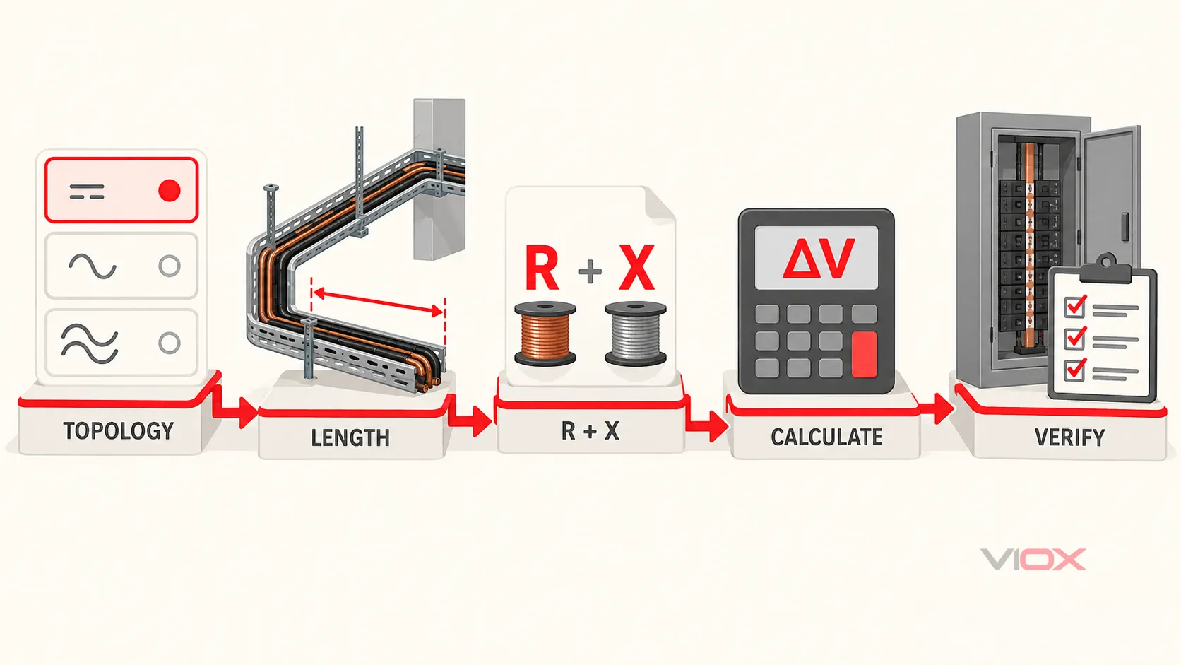
- កំណត់ទម្រង់សៀគ្វីអគ្គិសនី។. ជ្រើសរើសរវាង DC ខ្សែពីរ, AC ហ្វាសតែមួយខ្សែពីរ, ឬ AC បីហ្វាសដែលមានតុល្យភាព។ កុំប្រើរូបមន្តសម្រាប់ប្រព័ន្ធមានតុល្យភាពចំពោះសៀគ្វីដែលមិនមានតុល្យភាពជាក់ស្តែង។.
- កំណត់មូលដ្ឋានតង់ស្យុង។. សម្រាប់លទ្ធផលបីហ្វាសដែលមានតុល្យភាព សូមប្រើតង់ស្យុងរវាងខ្សែនិងខ្សែ (line-to-line) នៅពេលគណនាភាគរយនៃការធ្លាក់ចុះតង់ស្យុង។ សម្រាប់សាខាពីហ្វាសទៅខ្សែណឺត (phase-to-neutral) សូមប្រើតង់ស្យុងរវាងហ្វាសនិងខ្សែណឺត និងម៉ូដែលសៀគ្វីដែលសមស្រប។.
- វាស់ប្រវែងផ្លូវដើរខ្សែតែមួយទិស។. អនុវត្តតាមផ្លូវដើររបស់ខ្សែចំលង មិនមែនចម្ងាយជាបន្ទាត់ត្រង់រវាងឧបករណ៍នោះទេ។.
- កំណត់ចរន្តរចនាដោយផ្អែកលើផ្នែកនីមួយៗ។. ប្រើចរន្តផ្ទុកដែលរំពឹងទុកសម្រាប់លក្ខខណ្ឌប្រតិបត្តិការដែលកំពុងត្រួតពិនិត្យ។ លក្ខខណ្ឌនៃការចាប់ផ្តើម ការសាកថ្ម ឬលក្ខខណ្ឌបណ្តោះអាសន្នផ្សេងទៀត ទាមទារឱ្យមានការសិក្សាដោយឡែកពីគ្នា។.
- ទទួលបានទិន្នន័យខ្សែចំលងដែលត្រូវគ្នា។. ប្រើតម្លៃភាពធន់ និងភាពប្រតិកម្មដែលមានឯកតាដូចគ្នា និងសីតុណ្ហភាព សម្ភារៈ ការសាងសង់ និងការរៀបចំដំឡើងដែលសមស្រប។.
- គណនាវ៉ុល និងភាគរយ។. រក្សាឯកតាទាំងអស់ឱ្យអាចមើលឃើញ បន្ទាប់មកគណនាវ៉ុលនៅចុងបញ្ចប់នៃការទទួល។.
- ប្រៀបធៀបជាមួយដែនកំណត់ត្រឹមត្រូវ។. ពិនិត្យមើលកូដដែលបានអនុម័ត លក្ខណៈបច្ចេកទេសនៃគម្រោង ជួរបញ្ចូលរបស់ឧបករណ៍ និងតម្រូវការដំណើរការ។ មិនមានភាគរយនៃការធ្លាក់ចុះវ៉ុលជាសកលតែមួយសម្រាប់គ្រប់សៀគ្វីនោះទេ។.
- ផ្ទៀងផ្ទាត់ការរចនាទាំងមូល។. សមត្ថភាពផ្ទុកចរន្ត (Ampacity) ការកែតម្រូវសីតុណ្ហភាព ការដាក់ជាក្រុម ស្ថានីយ ការសម្របសម្រួលឧបករណ៍ការពារ ដំណើរការរង្វិលជុំកំហុស និងការធ្លាក់ចុះវ៉ុល គឺជាការត្រួតពិនិត្យដាច់ដោយឡែកពីគ្នា។.
កំហុសទូទៅដែលធ្វើឱ្យផ្លាស់ប្តូរចម្លើយ
| កំហុស | មូលហេតុដែលលទ្ធផលមិនត្រឹមត្រូវ | វិធីសាស្រ្តត្រឹមត្រូវ |
|---|---|---|
| ការគុណនឹងពីរលើប្រវែងរង្វិលដែលបានវាស់ | នេះ។ 2 កត្តាត្រូវបានអនុវត្តពីរដង |
ប្រើប្រវែងផ្លូវតែមួយជាមួយរូបមន្តខ្សែពីរតាមស្តង់ដារ ឬប្រើភាពធន់នៃរង្វិលដោយមិនចាំបាច់ប្រើកត្តាផ្សេងទៀតនៃ 2 |
| ការប្រើភាពធន់ DC សម្រាប់រាល់ខ្សែបញ្ជូន AC | វាខកខានមិនបានគិតពីផលប៉ះពាល់នៃភាពធន់ AC និងប្រតិកម្មអាំងឌុចស្យុង | ប្រើទិន្នន័យខ្សែ ឬទិន្នន័យពីក្រុមហ៊ុនផលិតដែលសមស្របនឹងការដំឡើង AC |
| ការមិនគិតពីសីតុណ្ហភាពរបស់ខ្សែចំលង | ភាពធន់កើនឡើងនៅពេលដែលខ្សែចម្លងឡើងកម្ដៅ | ប្រើប្រាស់ភាពធន់នៅលក្ខខណ្ឌប្រតិបត្តិការដែលពាក់ព័ន្ធ ឬអនុវត្តការកែតម្រូវដែលមានចែងក្នុងឯកសារ |
| ការចែកការធ្លាក់ចុះតង់ស្យុងបីហ្វាសដោយតង់ស្យុងរវាងហ្វាសនិងខ្សែណឺត | មូលដ្ឋានភាគរយមិនត្រូវគ្នានឹងលទ្ធផលរវាងខ្សែនិងខ្សែនោះទេ | ចែក Delta V_LL ដោយតង់ស្យុងបន្ទាប់បន្សំរវាងខ្សែនិងខ្សែ |
| ការចាត់ទុកការធ្លាក់ចុះតង់ស្យុងដូចជាសមត្ថភាពផ្ទុកចរន្ត | ខ្សែចម្លងដែលមានការធ្លាក់ចុះតង់ស្យុងទាបនៅតែអាចមិនសមស្របតាមលក្ខខណ្ឌកម្ដៅ ហើយក៏ផ្ទុយមកវិញដែរ | ផ្ទៀងផ្ទាត់សមត្ថភាពផ្ទុកចរន្ត និងការធ្លាក់ចុះតង់ស្យុងដោយឡែកពីគ្នា |
| ការអនុវត្តចរន្តមួយទៅលើខ្សែមេដែលចែកចាយ | ផ្នែកខាងលើ និងផ្នែកខាងក្រោមនៃសៀគ្វីផ្ទុកចរន្តខុសគ្នា | គណនាផ្នែកនីមួយៗ និងបូកសរុបការធ្លាក់ចុះតង់ស្យុង |
| ការប្រើប្រាស់ចរន្តក្នុងស្ថានភាពនឹងនរសម្រាប់ការចាប់ផ្ដើមម៉ូទ័រ | ចរន្តចាប់ផ្ដើម និងភាពធន់នៃប្រភពអាចជះឥទ្ធិពលលើការធ្លាក់ចុះតង់ស្យុងបណ្ដោះអាសន្ន | ធ្វើការសិក្សាអំពីការចាប់ផ្ដើមម៉ូទ័រ ឬការសិក្សាអំពីតង់ស្យុងថាមវន្ត |
នៅពេលដែលរូបមន្តសម្រួលមិនគ្រប់គ្រាន់
ប្រើប្រាស់គំរូសៀគ្វីដែលពេញលេញជាងនេះ ឬការសិក្សាផ្នែកវិស្វកម្ម នៅពេលដែលប្រព័ន្ធរួមមាន៖
- បន្ទុកបីហ្វាសដែលមិនមានតុល្យភាពជាក់ស្តែង;
- ចរន្តអព្យាក្រឹត ឬអាម៉ូនិកលេខបី (triplen harmonics) ដែលមានកម្រិតខ្ពស់;
- បន្ទុកមិនលីនេអ៊ែរ ដែលកត្តាថាមពលផ្លាស់ទី (displacement power factor) មិនអាចពិពណ៌នាអំពីទម្រង់រលកបានគ្រប់គ្រាន់;
- ការចាប់ផ្តើមដំណើរការម៉ូទ័រ ការបញ្ចូលថាមពលទៅក្នុងត្រង់ស្វ័រ ឬព្រឹត្តិការណ៍បណ្តោះអាសន្នផ្សេងទៀត;
- ខ្សែចម្លងស្របគ្នា ឬធរណីមាត្រនៃខ្សែចម្លងដែលមានភាពស្មុគស្មាញ;
- ខ្សែបញ្ជូនថាមពលវែង ដែលប្រភព ត្រង់ស្វ័រ និងភាពរាំងស្ទះនៃការតភ្ជាប់ប៉ះពាល់យ៉ាងខ្លាំងដល់វ៉ុលនៅស្ថានីយ;
- ការផលិតថាមពលចែកចាយ ដែលកង្វល់អាចជាការកើនឡើងនៃវ៉ុល ជាជាងការធ្លាក់ចុះវ៉ុលនៅផ្នែកបន្ទុក;
- បន្ទុកដែលមានសារៈសំខាន់ចំពោះសុវត្ថិភាព ដែលមានចន្លោះវ៉ុលប្រតិបត្តិការតូចចង្អៀត។.
នេះ។ មគ្គុទ្ទេសក៍ការបាត់បង់ថាមពលលើខ្សែបញ្ជូន VIOX ពន្យល់ពីទំនាក់ទំនងដាច់ដោយឡែករវាងចរន្ត អាំងតង់ស៊ីតេ និងការបាត់បង់ថាមពលពិត។ ការធ្លាក់ចុះតង់ស្យុង និងការបាត់បង់ថាមពលមានទំនាក់ទំនងគ្នា ប៉ុន្តែវាមិនអាចជំនួសគ្នាទៅវិញទៅមកបានទេ៖ ការធ្លាក់ចុះតង់ស្យុងទាក់ទងនឹងភាពខុសគ្នានៃតង់ស្យុងដែលផ្ទុកទទួលបាន ខណៈពេលដែលការបាត់បង់ថាមពលពិតរបស់ខ្សែចំលងគឺសំខាន់បំផុតគឺ I^2R.
សម្រាប់ការជ្រើសរើសខ្សែភ្លើងនៅក្នុងកម្មវិធីផ្ទាំងបញ្ជា សូមបន្តជាមួយ មគ្គុទ្ទេសក៍ស្តីពីការកំណត់ទំហំខ្សែភ្លើង IEC ការកាត់បន្ថយសមត្ថភាព ការធ្លាក់ចុះតង់ស្យុង និងការដាក់ក្នុងរង្វង់ខ្សែ. ប្រសិនបើអ្នកត្រូវការធ្វើការសម្របសម្រួលរវាងការកំណត់ឈ្មោះខ្សែភ្លើងតាមប្រព័ន្ធម៉ែត្រ និងអាមេរិកខាងជើង មុនពេលពិនិត្យមើលទិន្នន័យរបស់អ្នកផលិត សូមប្រើ មគ្គុទ្ទេសក៍បំប្លែងទំហំខ្សែភ្លើងពី AWG ទៅ mm2.
ដែនកំណត់នៃការធ្លាក់ចុះតង់ស្យុងអាស្រ័យលើច្បាប់ដែលអនុវត្ត
IEC 60364-5-52:2009+A1:2024 គ្របដណ្តប់លើការជ្រើសរើស និងការដំឡើងប្រព័ន្ធខ្សែភ្លើងតង់ស្យុងទាប។ មាត្រា 525 របស់វាដោះស្រាយអំពីការធ្លាក់ចុះតង់ស្យុង និងចង្អុលបង្ហាញទៅឧបសម្ព័ន្ធដែលពាក់ព័ន្ធសម្រាប់តម្លៃអតិបរមា។ តម្លៃដែលអាចអនុវត្តបានអាស្រ័យលើបរិបទនៃការដំឡើង និងច្បាប់ដែលបានអនុម័ត ដូច្នេះស្តង់ដារនេះត្រូវតែប្រើប្រាស់ស្របតាមតម្រូវការគម្រោង និងការអនុវត្តថ្នាក់ជាតិ។.
នៅក្នុងការងារនៅសហរដ្ឋអាមេរិក តម្លៃដែលត្រូវបានលើកឡើងជាទូទៅ 3% និង 5% បង្ហាញនៅក្នុងបរិបទនៃកំណត់សម្គាល់ព័ត៌មានរបស់ National Electrical Code ជាការណែនាំសម្រាប់ប្រសិទ្ធភាពប្រតិបត្តិការសមហេតុផល មិនមែនជាច្បាប់សកលសម្រាប់គ្រប់សៀគ្វីនោះទេ។ កម្មវិធីមួយចំនួនមានតម្រូវការចាំបាច់ដាច់ដោយឡែក។ សូមផ្ទៀងផ្ទាត់ការបោះពុម្ពដែលបានអនុម័ត អាជ្ញាធរដែលមានយុត្តាធិការ ការណែនាំអំពីឧបករណ៍ និងលក្ខណៈបច្ចេកទេសរបស់គម្រោង ជំនួសឱ្យការប្រើប្រាស់ភាគរយតែមួយជាសកល។ ភាពខុសគ្នានេះអាចមើលឃើញនៅក្នុងឯកសារផ្លូវការរបស់ NFPA ឯកសារអភិវឌ្ឍន៍កូដ NEC ឆ្នាំ 2025.
បញ្ជីត្រួតពិនិត្យការគណនា
មុនពេលទទួលយកលទ្ធផល សូមបញ្ជាក់ថា៖
- ថូបូឡូស៊ីសៀគ្វី និងមូលដ្ឋានតង់ស្យុងគឺត្រឹមត្រូវ;
- ប្រវែងមានន័យថាជាផ្លូវធ្វើដំណើរមួយផ្លូវជាក់ស្តែង លុះត្រាតែទិន្នន័យប្រើប្រាស់ប្រវែងរង្វិលយ៉ាងច្បាស់លាស់;
រ,X, និងអិលប្រើប្រាស់ឯកតាដែលត្រូវគ្នា;- ភាពធន់បង្ហាញពីចំហាយអគ្គិសនី និងលក្ខខណ្ឌប្រតិបត្តិការដែលពាក់ព័ន្ធ;
- ចរន្ត និងកត្តាថាមពលពិពណ៌នាអំពីផ្នែក និងស្ថានភាពប្រតិបត្តិការដែលកំពុងត្រួតពិនិត្យ;
- ការធ្លាក់ចុះតង់ស្យុងនៅខ្សែមេ (feeder) និងខ្សែសាខា (branch) ត្រូវបានបូកបញ្ចូលគ្នាក្នុងករណីដែលទាំងពីររួមចំណែក;
- លទ្ធផលត្រូវបានប្រៀបធៀបជាមួយនឹងតម្រូវការរបស់ឧបករណ៍ គម្រោង និងយុត្តាធិការ;
- សមត្ថភាពផ្ទុកចរន្តរបស់ចំហាយអគ្គិសនី និងការការពារត្រូវបានផ្ទៀងផ្ទាត់ដោយឯករាជ្យ។.
ប្រើ ម៉ាស៊ីនគណនាការធ្លាក់ចុះតង់ស្យុង VIOX ដើម្បីពិនិត្យមើលការរចនាបឋមយ៉ាងរហ័ស។ សម្រាប់ការរចនាចុងក្រោយ សូមរក្សាទុកទិន្នន័យបញ្ចូល ទិន្នន័យប្រភពចំហាយអគ្គិសនី ការសន្មត រូបមន្ត និងលក្ខណៈវិនិច្ឆ័យនៃការទទួលយក ដើម្បីឱ្យវិស្វករម្នាក់ទៀតអាចធ្វើការផ្ទៀងផ្ទាត់លទ្ធផលឡើងវិញបាន។.
ប្រភព និងស្តង់ដារ
- IEC 60364-5-52:2009+A1:2024, ការដំឡើងប្រព័ន្ធអគ្គិសនីតង់ស្យុងទាប – ប្រព័ន្ធខ្សែភ្លើង
- Seattle Public Utilities, ការគណនាសម្រាប់ការរចនាប្រព័ន្ធអគ្គិសនី, ខែកុម្ភៈ ឆ្នាំ 2024
- ឯកសារអភិវឌ្ឍន៍ក្រម NFPA 70 ឆ្នាំ 2025
កំណត់សម្គាល់ការពិនិត្យបច្ចេកទេស៖ អត្ថបទនេះផ្តល់នូវវិធីសាស្ត្រគណនាស្ថានភាពថេរប្រកបដោយតម្លាភាព ដែលមិនមែនជាការជំនួសសម្រាប់ការជ្រើសរើសខ្សែចំលងជាក់លាក់តាមគម្រោង ការពិនិត្យក្រម ឬការសិក្សាអំពីប្រព័ន្ធអគ្គិសនីនោះទេ។.