VIOXエレクトリック
Language

アイソレータスイッチの選び方:電流、電圧、極数、デューティ、および筐体

How to Choose an Isolator Switch: 7 Checks

執筆者:

カテゴリ:

To choose an isolator switch, first define what the device must do: provide isolation only, make and break normal load current, or combine switching with fuse protection. Then verify the supply and rated operational voltage (Ue), rated operational current (Ie) under the correct utilization category and installation conditions, pole/contact arrangement, short-circuit coordination, construction, enclosure, and destination-market documentation.

Do not select from the ampere value alone. A device marked 63 A may have different usable ratings for a resistive load, a motor load, an enclosed installation, or a different voltage. It also may be a disconnector rather than a load-switching device. If you are not yet sure which function you need, start with what an isolator switch does.

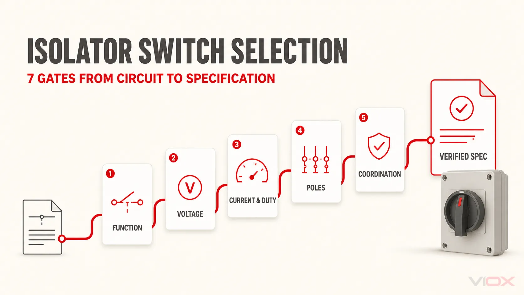
The Seven-Gate Isolator Switch Selection Worksheet

Treat each row as a gate. A product proceeds only when its exact datasheet, marking, diagram, and supporting documentation answer the requirement.

ゲート Input you must know What the selected device must prove Reject or pause when
1.機能 Isolation only, normal load switching, or switching plus fuse protection Declared disconnector, switch-disconnector, or fuse switch-disconnector function The commercial name is the only evidence of duty
2. Supply and voltage AC or DC, system voltage, frequency, and relevant transient environment Ue and supply-type rating match the circuit; other voltage ratings are interpreted correctly Only Ui, Uimp, or an AC rating is being used as proof of operational suitability
3. Current and load duty Normal load current, load type, switching frequency, ambient conditions, and enclosure Ie is adequate at the required voltage and utilization category under the stated conditions Selection relies on the headline current or a universal percentage margin
4. Poles and contacts Conductors to be disconnected and required neutral behavior Pole count and contact diagram match the circuit design A label such as 3P+N or 4P is accepted without checking the diagram
5. Short-circuit coordination Prospective short-circuit current and upstream short-circuit protective device (SCPD) Icw, Icm, conditional short-circuit data, and the specified SCPD arrangement are adequate where applicable The switch is assumed to clear a fault like a circuit breaker
6. Construction and enclosure Mounting, handle, shaft, lockability, interlocking, access, dust, water, temperature, and location The complete assembly—not just the internal switch—fits the mechanical and environmental requirement An internal device rating is assumed to apply to the finished enclosure
7. Market evidence Destination country, equipment category, product standard, and project documentation The exact model has the required approval, certificate, instructions, and accessory compatibility A family brochure or logo is substituted for model-level evidence

The order matters. A product that fails the function gate cannot be rescued by a higher current rating, and a product that fails short-circuit coordination cannot be rescued by a stronger enclosure.

Gate 1: Choose the Function Before the Rating

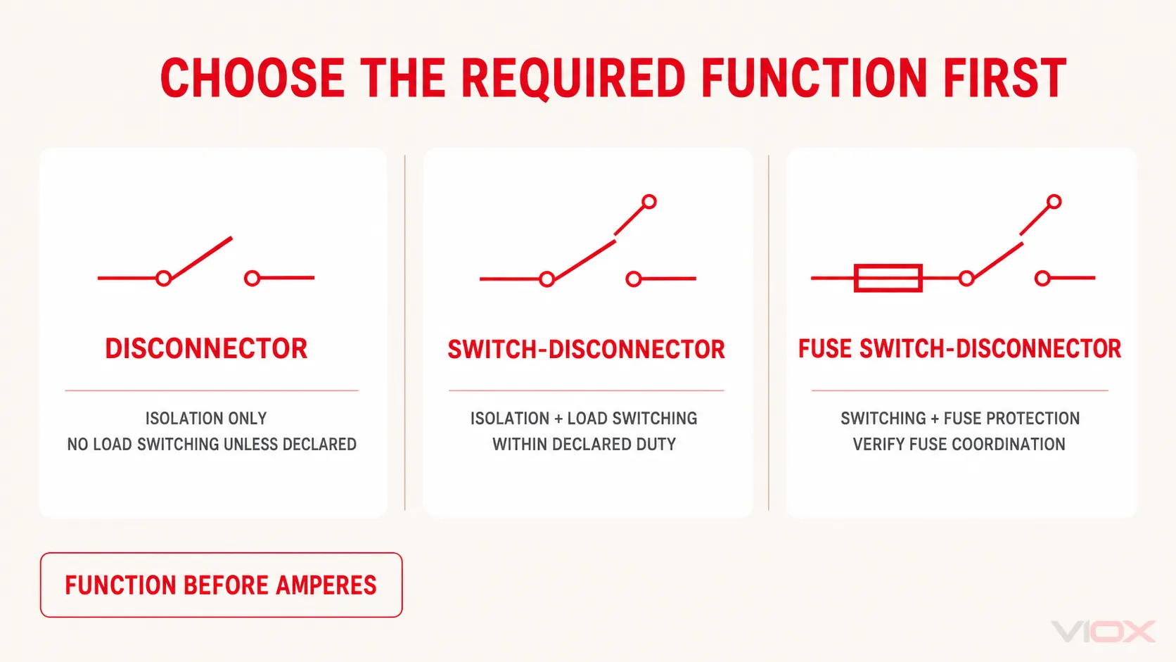
The term “isolator switch” is used loosely in catalogs and procurement. Convert it into one of three functional requirements before comparing products.

Required system function Device path to evaluate Key boundary
Establish an isolation function in the open position 断路器 Do not assume it can interrupt normal load current
Establish isolation and make/break current in normal service 開閉器(スイッチ・ディスコネクタ) Verify the declared utilization category and operational rating
Establish switching/isolation and integrate fuse links ヒューズ付きスイッチ断路器 Verify both the switching duty and the exact fuse/coordination arrangement

Functional selection among a disconnector, switch-disconnector, and fuse switch-disconnector

A switch-disconnector can make or break its rated current under its declared conditions, but it does not automatically detect an overload or short circuit. It normally depends on a coordinated upstream or integrated protective device. The full terminology boundary is covered in アイソレータ対断路器対スイッチ断路器.

If the real question is whether the system needs an isolator or a protective breaker, use the separate 回路遮断器とアイソレータスイッチの比較ガイド. Do not solve that architecture decision by choosing a larger isolator.

Gate 2: Match the Supply and Operational Voltage

Start with the circuit, not the product label:

  • Is the supply AC or DC?
  • What is the maximum operational voltage the device will experience?
  • For AC, what is the system frequency?
  • Does the project require a particular insulation or impulse-withstand level?
  • Does the manufacturer require a specific pole arrangement to achieve a stated DC voltage?

The rated operational voltage is the primary voltage value for the intended operating duty. Other values on a datasheet serve different purposes:

表示 確立される内容 What it does not establish by itself
Ue — 定格動作電圧 The voltage at which operational performance is declared with the associated duty Suitability at every current, utilization category, or supply type
Ui — rated insulation voltage The voltage reference used for insulation-related coordination and tests Permission to operate the device continuously at Ui
Uimp — rated impulse withstand voltage The declared ability to withstand specified impulse stress Normal load-switching or short-circuit interruption capability

Never transfer an AC rating to a DC circuit by assumption. DC selection can require source-specific voltage calculations, polarity rules, and series-connected poles; those belong in the DC isolator selection guide and the separate DC rating reader.

Gate 3: Match Ie to the Actual Load Duty

The relevant current is not simply the largest ampere number on the page. Verify the rated operational current Ie at the required Ue and utilization category, then check the conditions attached to that rating.

Manufacturer catalogs may also show conventional free-air thermal current (Ith), enclosed thermal current (Ithe), or another thermal value. These can help explain temperature-rise limits, but they are not automatic substitutes for Ie under the required switching duty.

Use the Utilization Category, Not a Generic Load Label

For IEC-oriented AC switch-disconnectors, the load determines the utilization category. The categories below are a selection map, not a replacement for the exact product table.

IEC utilization family General duty represented 選定上の留意点
AC-20 無負荷状態での接続と切断 Appropriate only when the declared operating arrangement does not require load switching
AC-21 Resistive loads, including moderate overloads Verify Ie at the project voltage and the required A/B duty suffix
AC-22 Mixed resistive and inductive loads, including moderate overloads Do not select from the AC-21 current value
AC-23 Motor loads or other highly inductive loads Verify the manufacturer’s AC-23 current or power table at the actual voltage

In IEC utilization-category notation, an A suffix identifies frequent operation and B identifies infrequent operation. A device can therefore have different declarations such as AC-23A and AC-23B. Schneider Electric’s official switch-disconnector guidance illustrates why the category must be read alongside Ie rather than treated as an accessory specification.

Also check whether the published current assumes open-air mounting, an enclosure, a maximum ambient temperature, a particular terminal/conductor arrangement, or another installation condition. Apply only manufacturer-supported derating. There is no defensible universal rule that every isolator should be selected at load current plus 25%.

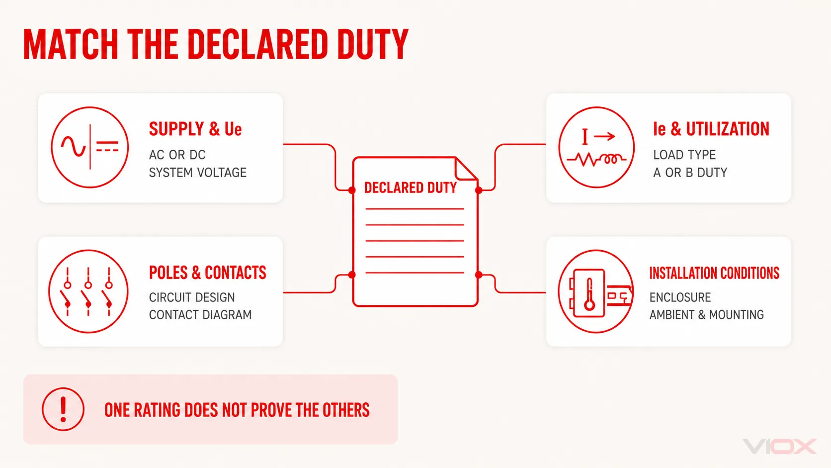
Declared isolator-switch duty mapped across supply, current, utilization, poles, and installation conditions

Gate 4: Verify Poles and Contact Behavior

Pole selection starts with the circuit design: identify every conductor the isolation function is required to disconnect and what must happen to the neutral, if present. Then verify the product’s contact diagram.

Do not treat the labels below as globally interchangeable:

  • 3P normally indicates three operated poles, but it does not answer whether a neutral exists elsewhere in the system.
  • 3P+N can indicate a neutral path with behavior that differs from the phase poles; the exact diagram decides whether and how it switches.
  • 4P indicates four poles, but it does not by itself prove a required sequence, neutral rating, or first-make/last-break behavior.

The correct arrangement depends on the earthing system, source configuration, transfer or parallel paths, local installation rules, and the equipment being isolated. For the deeper system question, use the 3相絶縁スイッチガイド and the manufacturer’s wiring/contact diagram. This selection page does not provide a universal 3P-versus-4P answer.

Gate 5: Prove Short-Circuit Coordination

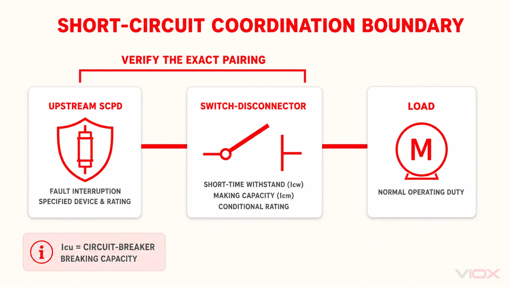
A switch-disconnector is not a circuit breaker. It may have declared short-circuit withstand and making capabilities, but it is not selected by assuming it will automatically interrupt prospective fault current.

Parameter or declaration Selection meaning よくある誤解
Icw — rated short-time withstand current Current the device can withstand for the declared duration under specified conditions Treating withstand as automatic fault interruption
Icm — rated short-circuit making capacity Peak current the device can make under declared short-circuit conditions Treating making capacity as breaking capacity
Conditional short-circuit current Prospective current the device can withstand when protected by a specified SCPD and arrangement Using the value without the named protective device or conditions
Icu — ultimate short-circuit breaking capacity A circuit-breaker interruption parameter Applying a breaker field as the universal isolator requirement

Schneider Electric explicitly notes that a load switch may have 定格短時間電流(Icw) そして Icm, but does not have イク under the cited IEC switch-disconnector framework. Its technical clarification is a useful check against procurement forms that ask every switching device for the same “breaking capacity.”

Short-circuit coordination boundary between the upstream SCPD, switch-disconnector, and load

Complete this gate by recording:

  1. 設置点における想定短絡電流;
  2. the exact upstream fuse or circuit breaker;
  3. the switch-disconnector’s standalone withstand/making declarations;
  4. any conditional rating and the exact SCPD, rating, and configuration on which it depends; and
  5. whether the finished assembly requires separate verification.

IEC 60947-3:2020+AMD1:2025 covers switches, disconnectors, switch-disconnectors, and fuse-combination units within its stated low-voltage scope. The IEC page also identifies conditional short-circuit rating requirements for devices protected by circuit breakers as a significant technical change. That product-standard scope does not replace the installation design or assembly assessment.

Gate 6: Select the Construction, Operator, and Enclosure

Once the electrical duty passes, match the physical implementation to the equipment.

選定項目 解決すべき課題
取り付け形式 DIN rail, base/panel mounted, door coupled, or complete enclosed assembly?
オペレーター Direct handle or external handle and shaft? Is the shaft length compatible with the enclosure depth?
Position and isolation indication What marking or mechanism proves the declared contact position and isolation function?
Locking and interlocking Is padlocking required? Must the enclosure door remain interlocked while the switch is closed? What defeat method, if any, is documented?
終了 Do conductor type, cross-section, lug, terminal orientation, and access match the exact model instructions?
アクセサリー Are auxiliary contacts, neutral modules, fuse carriers, terminal shields, or handles approved for the selected frame?
環境 What complete-assembly IP or NEMA enclosure rating, ambient range, pollution conditions, altitude, corrosion resistance, or UV resistance is required?

An IP code belongs to the tested or declared enclosure arrangement. A switch mechanism mounted inside a box does not automatically give the finished assembly the box’s published protection level, especially after handles, shafts, cable entries, drains, or other penetrations are added. Use the detailed indoor vs outdoor isolator switch guide when the environmental decision needs a full IP analysis.

Gate 7: Verify the Destination-Market Evidence

Standards and category names are not interchangeable across markets. For an IEC-oriented project, the relevant product family is commonly assessed under IEC 60947-3. The official IEC scope covers distribution and motor circuits up to the limits stated on its publication page; it does not prove that a particular VIOX or third-party model holds a specific certificate.

North American projects may distinguish disconnects evaluated under UL 98 from some manual motor controllers evaluated under UL 508 or other applicable categories. UL Solutions gives a concrete machinery example: where a non-fused motor-circuit horsepower-rated switch is used in the stated feeder/disconnect context, it calls for a UL 98 non-fused disconnect rather than a UL 508 manual motor controller. See the official UL machine supply circuit and disconnecting means guidance.

For the exact model, request the documents that the destination market and project actually need:

  • current datasheet and installation instructions;
  • product-standard and approval information tied to the exact model;
  • utilization-category table at the required voltage;
  • pole/contact diagram and neutral behavior;
  • short-circuit withstand, making, and conditional-coordination data;
  • compatible handles, shafts, fuse links, terminals, and accessories; and
  • complete-enclosure environmental declarations where applicable.

Do not infer model approval from a family page, test logo, or another product in the same series.

Convert the Seven Gates into an RFQ Specification

Use the following record before comparing part numbers. Replace every bracketed item with project information or mark it as requiring engineering confirmation.

RFQ項目 プロジェクト入力
必要な機能 [遮断器 / スイッチ遮断器 / ヒューズ付きスイッチ遮断器]
電源 [AC or DC], [frequency if AC]
定格動作電圧 Ue ≥ [project requirement], under [applicable duty]
負荷 [resistive / mixed / motor or highly inductive / other defined load]
Rated operational current or power Ie ≥ [required value] at [Ue] and [utilization category]
動作デューティ [required A/B category or documented operating frequency]
Poles and contacts [pole count], [contact/neutral behavior], diagram required
短絡協調 [prospective current], [upstream SCPD], [required Icw/Icm/conditional declaration]
Mounting and operator [DIN rail / panel / door coupled / enclosed], [handle/shaft/interlock]
環境 [indoor/outdoor conditions], [required complete-assembly IP/NEMA], [ambient/altitude/corrosion conditions]
市場での実績 [destination country], [required standard/approval], model-level documents required
Accessories and terminals [conductor/terminal needs], [auxiliaries], [approved accessory list]

Bounded Example: Local Isolation for an AC Motor Load

Suppose a panel builder needs a local device that will routinely switch an AC motor load and provide an isolation function. The function gate points to a 断路器, not an isolation-only disconnector. The load gate then requires the manufacturer’s motor/highly-inductive utilization data—typically the appropriate AC-23 declaration—at the actual system voltage. The designer must still establish Ie or the applicable motor-power rating, required poles and neutral behavior, prospective short-circuit current, upstream SCPD coordination, operator and enclosure arrangement, and destination-market approval.

That statement is not a part-number recommendation. It shows how the load description changes the specification before current, poles, or enclosure are compared.

Move from Specification to Product Evaluation

After every gate has an answer, compare documented models in the VIOX アイソレータスイッチカテゴリ そして スイッチ断路器カテゴリ. For a technical enquiry, send the completed RFQ record, required quantity, and destination market to [email protected]. VIOX should confirm model-level ratings and documentation against the supplied requirement rather than selecting from the ampere value alone.

技術資料