On this page
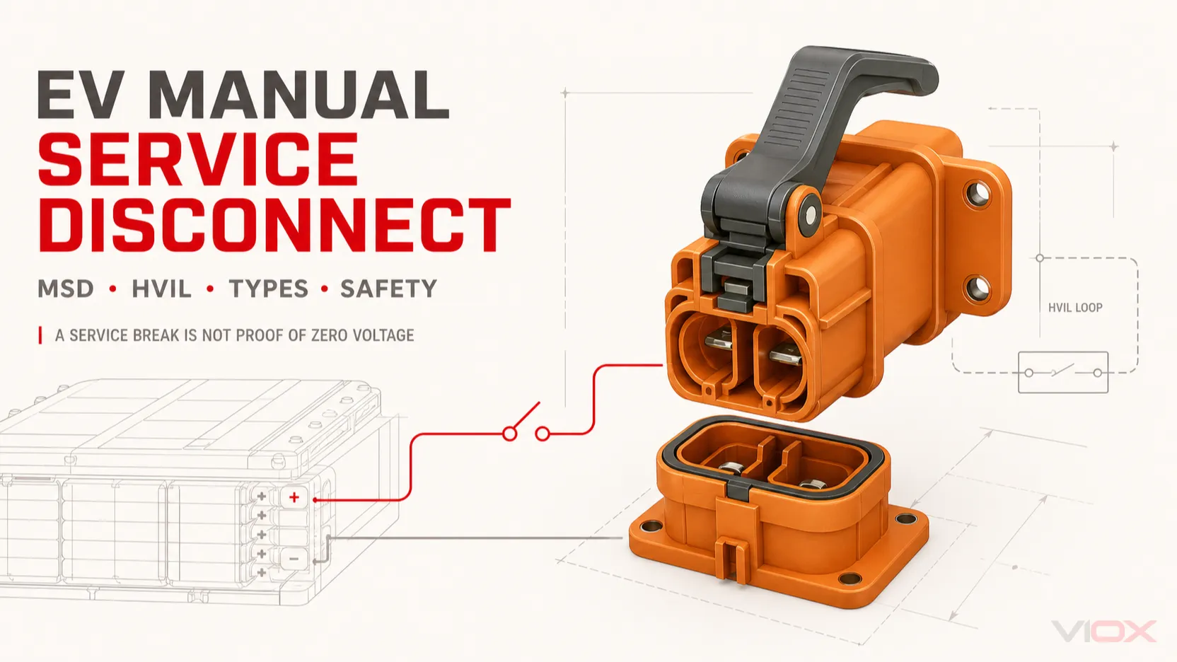
A manual service disconnect (MSD) is a removable high-voltage device that creates a service isolation point inside an electric vehicle (EV), hybrid vehicle or other high-voltage battery system. Many MSDs use a two-stage mechanism that opens the low-voltage High Voltage Interlock Loop (HVIL) before the main high-voltage contacts physically separate.
That sequence reduces the likelihood of disconnecting a live load, but it does not make MSD removal a complete safe-work procedure. An open HVIL, open contactors or removed service plug does not by itself prove that every high-voltage conductor is de-energized. Trained personnel must follow the exact vehicle or battery-system manufacturer’s shutdown, waiting-time, lockout, personal protective equipment and voltage-verification procedure.
| Question | Engineering answer |
|---|---|
| What does an MSD do? | It opens a defined high-voltage path in or around the battery pack for service isolation. |
| What does HVIL do? | It is a low-voltage monitoring loop that reports whether high-voltage connectors and covers are properly closed. |
| Does every MSD contain a fuse? | No. Fused and shunt (non-fused) versions exist. |
| Does removing the MSD prove zero voltage? | No. Contactors may fail, capacitors can retain charge and some battery sections may remain energized. |
| Can one generic removal procedure be used? | No. Sequence, discharge time, test points and re-energization steps are OEM- and model-specific. |
MSD Meaning and System Boundary
In EV documentation, MSD usually means Manual Service Disconnect. Other names include service disconnect, service plug, service disconnect plug and battery service disconnect. The exact term varies, but the defining function is a manually operated, service-oriented break in a high-voltage battery circuit.
An MSD is not automatically the same device as every orange high-voltage connector, nor is it the same as a building’s electrical service disconnect. The following distinctions matter:
| Device | Primary function | Normal actuation | Important boundary |
|---|---|---|---|
| Manual Service Disconnect | Creates a manual service break in a battery-pack HV path | Trained person, under an OEM procedure | May be fused or shunted; not proof of zero voltage |
| Main battery contactor | Connects and disconnects the battery electrically during vehicle operation | Battery management or vehicle control system | Electromechanical switching device; contacts can weld or fail |
| Manual battery disconnect switch | Provides a manually operated battery isolation function | Handle, lever or rotary mechanism | Architecture and ratings differ; may not be an EV pack service plug |
| Fuse | Interrupts specified overcurrent under its tested conditions | Melting element responds to current | Does not provide routine manual isolation |
| Pyrotechnic disconnect | Opens a battery path rapidly after a commanded event such as a crash | Electrically triggered pyrotechnic actuator | One-time device; not a routine service disconnect |
The MSD is therefore one part of a broader battery disconnect unit (BDU) or rechargeable energy storage system architecture. Contactors control normal operation, fuses manage specified overcurrent conditions, HVIL monitors connector integrity, and the MSD creates a deliberate physical service break.
For the broader difference between placing a manual battery switch in the positive or negative conductor, see Does a Battery Disconnect Switch Go on Positive or Negative?. That decision is related, but it does not replace the vehicle-specific MSD architecture.
How a Manual Service Disconnect Works
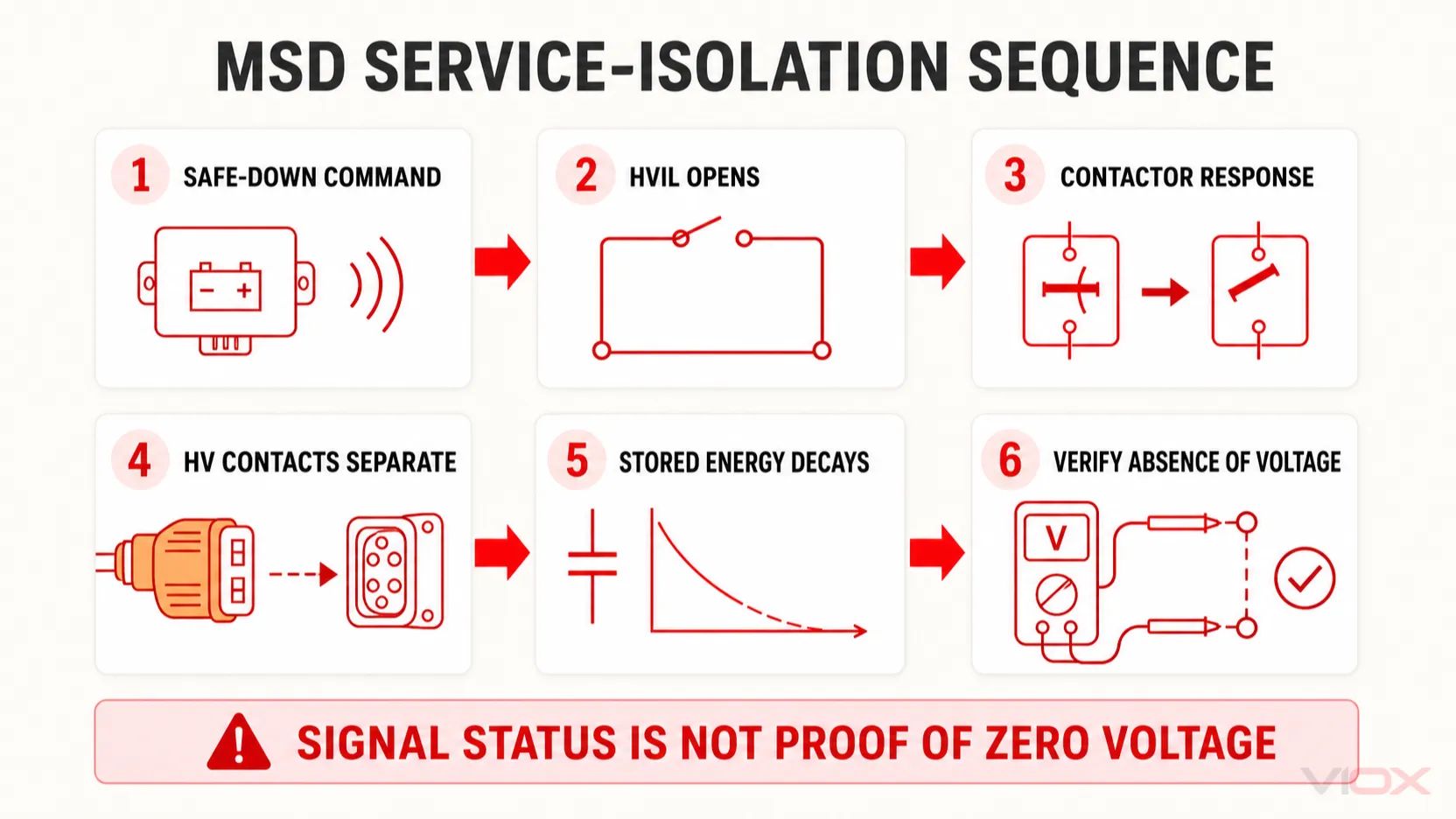
The most useful way to understand an MSD is to separate five events that are often incorrectly treated as one:
- the vehicle or battery system enters its specified safe-down state;
- the MSD mechanism opens the HVIL circuit;
- the control system detects the open interlock and manages the main contactors according to its design;
- the MSD’s main high-voltage contacts physically separate;
- stored energy decays and absence of voltage is verified at the prescribed points.
Stage 1: The system is commanded to a safe state
The approved service sequence normally begins before anyone operates the MSD. The vehicle or battery controller must be placed in the state specified by the manufacturer so that high-voltage loads are not drawing current and the main contactors can be commanded open.
The exact method is not universal. Ignition state, service mode, low-voltage supply isolation and diagnostic confirmation differ by vehicle and battery platform.
Stage 2: HVIL opens before the HV contacts separate
Aptiv describes HVIL as a continuous low-voltage loop that monitors high-voltage connectors and components. In a two-stage MSD, the first mechanical movement opens this monitoring circuit before the main power contacts disengage.
The control system can then detect that the service connection is being opened and respond according to the system design. TE Connectivity’s AMP+ MSD, for example, uses a two-stage lever that opens the HVIL before separating the high-voltage contacts.
HVIL is a signaling and monitoring function. It does not itself interrupt hundreds of amperes of battery current and it does not independently confirm that contactor contacts have opened.
Stage 3: Main contactors change the operating state
In a typical architecture, the battery management or vehicle control system responds to the interlock state by opening the positive and negative main contactors. This is intended to remove load current from the downstream high-voltage bus before the MSD’s power contacts separate.
However, a control command is not physical proof. A contactor can weld, a feedback circuit can fail, or a system can be configured differently. The MSD sequence reduces risk only when the complete architecture and diagnostic controls operate as intended.
Stage 4: The MSD creates a physical break
Further lever movement separates the MSD’s high-voltage contacts. Depending on pack architecture, that break may divide the cell stack into lower-voltage sections, open one battery pole, or disconnect an external pack path.
The conductors on one or both sides can still remain energized relative to other conductors or chassis. The phrase “battery disconnected” should therefore be tied to a defined circuit boundary, not interpreted as meaning that the entire pack is electrically harmless.
Stage 5: Stored energy must discharge and voltage must be verified
Inverters, onboard chargers, DC-link capacitors, filters and other power electronics can retain hazardous energy after contactors open. Battery subassemblies upstream of the service break also remain energy sources.
The required wait time and test points come from the OEM service information, not from a universal rule. ISO 6469-3:2021 addresses electrical safety for voltage class B circuits in electrically propelled road vehicles, but its official scope explicitly states that it does not provide comprehensive safety information for manufacturing, maintenance and repair personnel. The repair procedure still requires the applicable OEM authority and qualified-person practices.
Inside an MSD: Components and Safety Interfaces
An MSD may look like a large orange plug, but its mechanical and electrical interfaces perform different tasks.
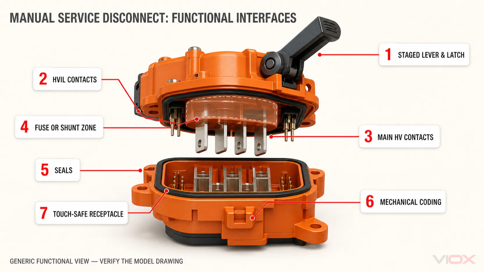
| Component | Function | What must be verified |
|---|---|---|
| Lever and latch | Controls staged engagement and disengagement | Full travel, locking sequence, damage and correct operation |
| HVIL contacts | Open before the main HV contacts in a staged design | Circuit arrangement, timing sequence and controller logic |
| Main HV contacts | Carry battery current and create the service break | Voltage, continuous current, temperature rise and contact condition |
| Fuse or shunt | Provides overcurrent protection or a solid conductive link | Exact configuration, fuse class/rating and system coordination |
| Receptacle and touch protection | Supports contacts and limits access to live parts | Mated and unmated protection stated for the exact product |
| Seals | Limit water and contaminant ingress | Mated/unmated IP condition, gasket damage and environment |
| Mechanical coding | Prevents mating of an incorrect variant | Key, color and part-number compatibility |
| Terminals and bus interfaces | Connect the MSD to pack conductors or busbars | Stud size, torque, plating, conductor geometry and assembly instructions |
An orange housing is a useful visual convention, not an electrical rating. Likewise, “touch-safe” does not mean that untrained work is permitted; it refers to a defined accessibility condition under a stated test framework and product state.
Fused MSD vs Shunt MSD
MSDs are commonly available in two architecture families.
Fused Manual Service Disconnect
A fused MSD places a high-voltage fuse in the removable plug or service path. It combines a service break with specified overcurrent interruption, reducing the number of separate high-current interfaces in some pack layouts.
The fuse must be coordinated with the battery’s prospective fault current, voltage, DC interruption duty, conductor protection, contactors and downstream equipment. The fuse ampere value is not the same as the MSD’s continuous-current capability. A manufacturer may publish a maximum fuse rating while specifying continuous current separately under a defined ambient condition.
If fuse selection is part of the design task, use the complete device curve and fault study rather than selecting by nominal current alone. The Electrical Fuse Types and Selection Guide explains the broader fuse variables.
Shunt or Non-Fused MSD
A shunt MSD replaces the integrated fuse with a conductive link. Overcurrent protection is then provided elsewhere in the battery system. This can suit architectures with a separate pack fuse or pyrotechnic protection device.
A shunt version should not be substituted for a fused version merely because the housing fits. Doing so can remove the protection function that the original pack design relies on. Conversely, inserting a fuse into a system designed around a shunt changes voltage drop, heat generation, coordination and service parts.
| Selection question | Fused MSD | Shunt MSD |
|---|---|---|
| Contains overcurrent element | Yes, for the specified fuse configuration | No; uses a conductive link |
| Requires separate pack protection | Depends on architecture and coordination | Normally yes |
| Voltage and current limits | Defined for the fused assembly and fuse | Defined for the shunt assembly |
| Main verification | Fuse rating, DC breaking capability and coordination | External protection and shunt current/thermal capability |
| Interchangeable with the other type | No assumption permitted | No assumption permitted |
Where the MSD Sits in the Battery Pack
MSD placement changes what becomes isolated and what remains energized.
Positive- or negative-bus service break
An MSD may open one battery pole between the cell stack and the external high-voltage distribution path. This interrupts one conductor but does not divide the internal stack voltage. Internal pack sections can remain at full potential relative to each other.
Mid-pack service disconnect
A mid-pack MSD divides a series cell stack into two sections. This can reduce the voltage present across selected service boundaries after the plug is removed, depending on the exact topology.
Mid-pack placement does not eliminate all hazardous voltage. Each section still stores energy, and measurement relative to chassis or across unintended points may produce a different result from the expected split voltage.
Pack-to-pack or module-section disconnect
Some platforms use a service disconnect between battery subpacks or at a high-voltage distribution interface. The engineering drawing must define the isolation boundary. Product appearance alone cannot reveal which conductors remain live.
How to Read MSD Ratings and Datasheets
Do not copy a competitor’s voltage, fuse or ingress-protection value into a new design. Request the exact product drawing, qualification evidence and installation instructions.
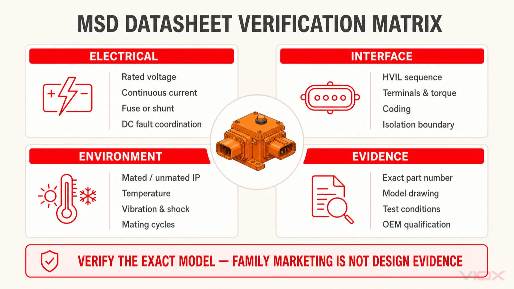
| Data field | Design question | Common specification error |
|---|---|---|
| Rated voltage | Is the fused or shunt version rated for the maximum pack voltage and DC duty? | Applying a shunt-version voltage to a fused version |
| Continuous current | Under what ambient temperature, cable/busbar size and thermal conditions is it declared? | Treating fuse ampere rating as continuous-current rating |
| Fuse rating and type | Which fuse series, curve, DC breaking rating and coordination apply? | Choosing only by amperes |
| HVIL arrangement | How many interlock circuits, what contact sequence and what controller diagnostics are used? | Assuming an open loop proves open contactors |
| Contact resistance and temperature rise | What are the initial limits and validation conditions? | Ignoring interface heating and aging |
| IP and touch protection | Does the rating apply mated, unmated, capped or under another defined condition? | Quoting one IP code for every state |
| Operating and storage temperature | Which range applies to the complete assembly and fuse? | Mixing storage and loaded operating limits |
| Mating cycles | Is the MSD intended for emergency-only, periodic service or production use? | Using it as a frequent switching connector |
| Terminals and torque | What stud, conductor, plating, joint stack and torque procedure apply? | Reusing a torque value from another model |
| Coding and color | Which key prevents incorrect voltage/current variants from mating? | Treating color as sufficient part identification |
| Qualification framework | Which USCAR, ISO, IEC, OEM or other evidence applies to the exact part? | Treating family-level marketing as model certification |
Example: why published family values must stay model-specific
TE Connectivity publishes an AMP+ MSD family with a two-stage lever, internal HVIL, fused and shunt versions and model-dependent electrical limits. Its current product page distinguishes a 450 VDC fused version from a 1000 VDC shunt version and states that current capability depends on fuse selection, with a maximum continuous-current condition for the family.
Those values illustrate why the suffix and architecture matter. They must not be generalized to every MSD or even every product in the same visual housing. Use the current model drawing and datasheet at the time of specification.
Safe Service Boundary: What This Guide Can and Cannot Tell You
This article explains system behavior; it is not a vehicle repair procedure. High-voltage service requires training, suitable test equipment and the exact OEM instructions.
At a minimum, the controlled procedure must define:
- how the specific vehicle or battery system is placed in a safe-down state;
- which low-voltage supplies or control circuits are disabled;
- the exact MSD release and anti-reinsertion method;
- the required discharge waiting time;
- the approved voltage-test instrument and proving method;
- the prescribed test points and acceptable result;
- personal protective equipment and work-area controls;
- how the pack is reassembled, inspected and safely re-energized.
Do not publish or follow a universal instruction such as “wait one minute” or “raise the lever to 45 degrees.” Those values can be correct for one model and unsafe for another.
Removing the MSD may leave hazardous voltage:
- inside each battery section;
- upstream of the service break;
- in capacitors downstream of the main contactors;
- on a circuit affected by welded contacts or wiring faults;
- at auxiliary high-voltage branches outside the assumed boundary.
Design and Inspection Failure Modes
MSD removed while current is still flowing
If control sequencing, contactors or operator procedure fail, the MSD contacts may separate under load. DC arcs do not benefit from natural AC current zero-crossings. The device must not be treated as a routine load-break switch unless its exact documentation permits that duty.
HVIL opens but the main contactor does not
A welded contactor, control fault or incorrect feedback assumption can leave the downstream bus energized. This is why the sequence requires voltage verification rather than trust in a dashboard indication alone.
High contact resistance develops at the MSD interface
Incomplete latching, contamination, reduced contact force, damaged plating, loose bus joints or repeated operation can increase resistance and temperature rise. Inspect for discoloration, deformation, odor, damaged seals and abnormal terminal heating according to the OEM criteria.
Wrong fused or shunt insert is installed
Mechanical similarity does not establish electrical equivalence. Verify complete part number, coding, fuse configuration, voltage, current and qualification evidence. Never bypass a rejection or coding feature.
Moisture protection is assumed in the unmated state
An ingress-protection declaration may differ between mated and unmated conditions. A removed plug can expose a receptacle that requires an approved cap or controlled environment.
MSD Specification Checklist
For an engineering review or RFQ, provide:
- maximum and nominal battery voltage;
- continuous current and the full thermal boundary conditions;
- expected short-circuit current and required protection architecture;
- fused or shunt configuration;
- fuse series, current, voltage, DC breaking capability and coordination data;
- HVIL contact arrangement and sequencing requirements;
- pack location and intended isolation boundary;
- terminal and busbar geometry;
- mated and unmated ingress/touch-protection requirements;
- operating and storage temperature;
- vibration, shock, chemical and environmental requirements;
- mating-cycle and service-frequency requirements;
- mechanical coding, connector-position assurance and anti-reinsertion needs;
- applicable OEM and market qualification evidence.
The adjacent Energy Storage Connector Guide explains broader high-current battery connector interfaces. An MSD should still be specified as a dedicated safety and service component rather than as a generic connector selected only by voltage and amperes.
Frequently Asked Questions
What is an MSD in an EV battery?
MSD stands for Manual Service Disconnect. It is a removable high-voltage device that creates a defined service break in the EV or hybrid battery circuit. Depending on the architecture, it may also contain a fuse.
Does an MSD disconnect both positive and negative conductors?
Not necessarily. Some designs open one battery pole, while mid-pack designs split the series cell stack. The schematic determines the isolation boundary and which conductors remain energized.
Is HVIL the same as the high-voltage circuit?
No. HVIL is normally a low-voltage monitoring loop routed through high-voltage connectors and covers. It signals connection integrity to the controller; it does not carry or directly interrupt traction current.
Can an MSD be pulled in an emergency?
Only according to the vehicle or battery manufacturer’s emergency and service instructions. Accessibility does not make an MSD safe for untrained or energized operation.
Is a fused MSD interchangeable with a shunt MSD?
No general interchangeability should be assumed. Replacing a fused MSD with a shunt can remove required overcurrent protection, while adding a fuse to a shunt architecture can change coordination and thermal performance.
Technical Sources
- TE Connectivity, AMP+ Manual Service Disconnect
- TE Connectivity, AMP+ Manual Service Disconnect technical sheet
- Aptiv, What Is HVIL?
- ISO 6469-3:2021, Electrically propelled road vehicles – Electrical safety
ISO 6469-3 provides a vehicle electrical-safety framework but explicitly does not supply comprehensive safety information for manufacturing, maintenance and repair personnel. Always use the applicable OEM service documentation for procedural decisions.