Sur cette page
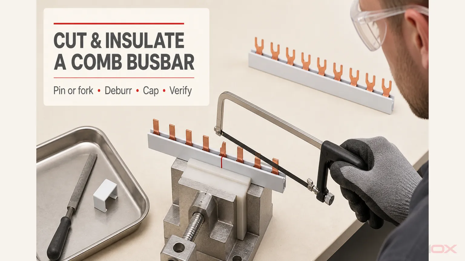
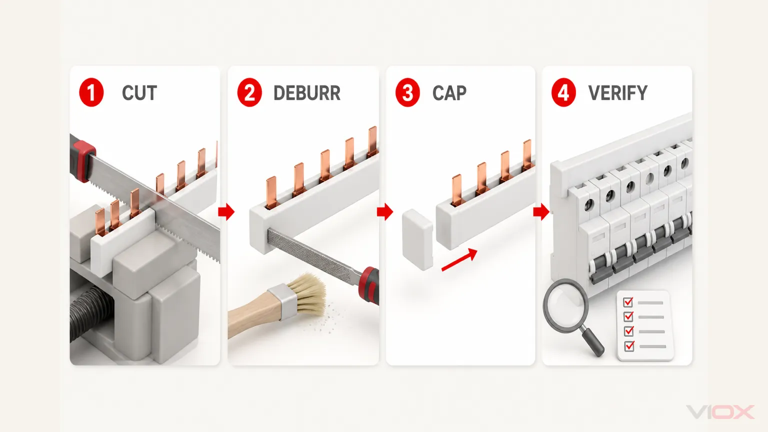
Ne coupez un peigne d'alimentation que si le produit spécifique est homologué pour la découpe. Mettez hors tension et vérifiez l'absence de tension dans le tableau, retirez le peigne, confirmez la dent et la séquence de phases requises, effectuez une coupe droite avec l'outil approuvé par le fabricant, éliminez les bavures et les débris conducteurs, et fermez l'extrémité coupée avec l'embout isolant correspondant. Protégez toutes les dents sous tension inutilisées avec les capuchons de protection spécifiés avant de réinstaller le peigne.
Ne présumez pas que tous les peignes pour disjoncteurs modulaires (MCB) peuvent être raccourcis. Certaines gammes de produits distinguent les peignes standards non recoupables des versions spécifiquement conçues pour la découpe. Le ruban isolant, la gaine thermorétractable générique, le mastic et un embout non adapté ne restaurent pas automatiquement l'isolation, les distances d'isolement ou la configuration d'assemblage documentée du produit.
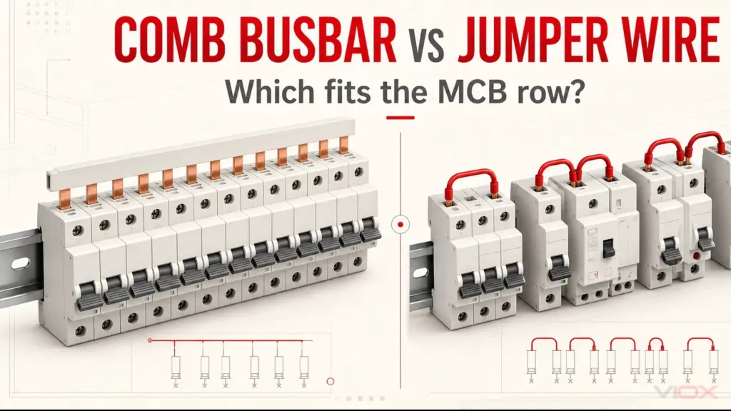
Ce guide concerne les peignes à broches et à fourches isolés des peignes de raccordement pour MCB utilisés sur des disjoncteurs modulaires compatibles et des dispositifs de protection associés. Il ne couvre pas les barres en cuivre fabriquées pour tableaux électriques, les jeux de barres préfabriqués ou les procédures de travail sous tension. La découpe et l'installation doivent être effectuées par un électricien qualifié conformément aux instructions de l'équipement et aux règles de sécurité du site.
Principaux enseignements
- Confirmez que le modèle exact de peigne est recoupable avant de le marquer ou de le couper.
- Retirez le peigne de l'assemblage hors tension ; ne le coupez jamais lorsqu'il est installé.
- Déterminer la longueur de coupe à partir de la rangée d'appareils réelle, de la géométrie des dents et de la séquence des pôles, et non uniquement à partir de la largeur du coffret.
- Utiliser la méthode de coupe et d'ébavurage approuvée pour ce produit ; une scie et une lime sont spécifiées pour certains systèmes, mais pas systématiquement pour tous.
- Installer l'embout de protection correspondant sur chaque extrémité coupée nécessitant une protection.
- Utiliser des caches-dents pour les contacts sous tension inutilisés lorsque la documentation du système l'exige.
- Rejeter la pièce si le conducteur, les dents ou l'isolation sont fissurés, déformés, surchauffés ou contaminés.
- Vérifier à nouveau la compatibilité, le positionnement, la séquence de phase, le serrage des bornes et la protection de l'assemblage terminé avant la mise sous tension.
Avant la coupe : quatre contrôles de conformité
L'opération de coupe commence par la documentation, et non par une scie. Réussir les quatre contrôles avant de modifier la pièce.
| Vérifier | Condition de réussite | Condition d'arrêt |
|---|---|---|
| Autorisation de découpe | Le numéro de catalogue exact ou les instructions du produit autorisent la découpe | La documentation est muette, le modèle est décrit comme étant à longueur fixe, ou la découpe est interdite |
| Géométrie de la rangée | Le type de dent, le pas, la profondeur des bornes et les positions des appareils correspondent à la rangée complète | La barre semble seulement s'adapter, les appareils ont des hauteurs de bornes différentes, ou les dents ne s'insèrent pas uniformément |
| Schéma électrique | La séquence des pôles, la disposition des phases, l'alimentation et les contacts requis sont identifiés sur le schéma de montage | La coupe est basée uniquement sur la longueur physique ou créerait une disposition phase/neutre peu claire |
| Protection d'extrémité | L'embout de finition correct et tous les cache-dents requis sont disponibles pour la gamme de jeux de barres exacte | La protection proposée est du ruban adhésif, de la gaine thermorétractable générique, du mastic ou un accessoire non adapté |
Si le jeu de barres n'a pas encore été sélectionné, utilisez le VIOX Guide de sélection des peignes de raccordement pour disjoncteurs modulaires (MCB) en premier. La coupe ne peut pas corriger une interface à broches ou à fourches, un pas, une disposition des pôles, des dimensions de contact ou une valeur nominale électrique incorrects.
Outils et pièces requis
Utilisez l'équipement nommé dans les instructions du jeu de barres ou du tableau de distribution. Une configuration de travail contrôlée typique peut inclure :
- le peigne d'alimentation sécable précis et ses instructions produit ;
- l'embout de finition correspondant à la gamme de peignes, à la configuration des pôles et au profil du conducteur ;
- les caches-dents ou capuchons de protection contre les contacts pour les dents inutilisées ;
- une scie à denture fine homologuée, une pince coupante pour peigne dédiée ou tout autre outil de coupe spécifié ;
- une lime fine ou un outil d'ébavurage homologué ;
- une règle de mesure, une équerre et un marqueur non abrasif ;
- un support de travail stable ou un étau à mors doux qui n'écrase pas l'isolation et ne plie pas les dents ;
- une protection oculaire, des gants de protection anti-coupure et tout autre équipement de protection individuelle (EPI) requis ;
- une brosse propre ou une méthode d'aspiration appropriée pour éliminer les particules métalliques ; et
- l'outil de serrage des bornes spécifié pour la réinstallation.
Par exemple, les instructions du tableau de répartition Easy9 de Schneider Electric indiquent à l'installateur d'utiliser une scie et des EPI, puis d'utiliser une lime pour arrondir les extrémités coupées. Il s'agit d'une preuve utile pour ce système d'équipement, et non d'une spécification d'outil universelle pour tous les peignes de raccordement.
Évitez d'utiliser des pinces coupantes, des coupe-boulons ou des pinces universelles comme méthode de coupe générale. Ils peuvent aplatir le conducteur, fendre l'isolant, tordre la dent ou laisser une coupe tranchante et irrégulière. Ne vous tournez pas systématiquement vers une meuleuse abrasive : la chaleur, les étincelles et les particules conductrices peuvent endommager l'isolation ou contaminer l'équipement, sauf si la procédure du produit autorise explicitement cette méthode.
Étape par étape : Comment couper un peigne de raccordement pour disjoncteur (MCB)
1. Isoler l'alimentation et vérifier que l'ensemble est hors tension
Suivez la procédure d'isolation, de consignation et de vérification du site. Identifiez toutes les sources possibles, y compris les alimentations alternatives le cas échéant. La position « arrêt » d'un disjoncteur ne suffit pas à garantir que le peigne peut être manipulé en toute sécurité.
Retirez le peigne de raccordement de la rangée d'appareillage avant de le couper. Cela empêche les copeaux métalliques de pénétrer dans les bornes des disjoncteurs, évite toute contrainte mécanique sur les appareils installés et offre à l'installateur un accès dégagé pour inspecter l'ensemble de la pièce.
Confirmez que le peigne d'alimentation spécifique est conçu pour être découpé.
Vérifiez la référence catalogue, le plan et la notice d'installation. Des produits d'apparence similaire au sein d'une même gamme peuvent avoir des règles de modification différentes.
Cette distinction est particulièrement importante lorsque le statut d'homologation est pertinent. Schneider Electric documente à la fois des peignes d'alimentation standard reconnus UL qui ne doivent pas être coupés et des versions sécables distinctes pour une gamme Multi 9 spécifique. De même, ABB identifie certaines familles de peignes comme étant adaptées à la découpe et répertorie les références d'embouts correspondantes. Ces exemples démontrent pourquoi une déclaration générique telle que “ tous les peignes d'alimentation sont sécables ” est incorrecte.
Pour les produits VIOX, vérifiez le modèle exact ou le plan avant toute modification. La gamme VIOX de peignes d'alimentation pour disjoncteurs modulaires (MCB) inclut des formats à broches et à fourches ainsi que de multiples configurations de pôles, mais l'autorisation de découpe et les accessoires requis restent spécifiques à chaque modèle.
3. Assemblez la rangée d'appareillage et identifiez les contacts requis.
Disposez les disjoncteurs modulaires (MCB), les interrupteurs différentiels (RCCB), les disjoncteurs différentiels (RCBO), les interrupteurs-sectionneurs ou tout autre appareil modulaire approuvé dans leur séquence finale. Confirmez :
- la famille exacte de disjoncteur et l'interface de raccordement ;
- géométrie à broches ou à fourches ;
- pas du module et tout espace ou auxiliaire ;
- configuration 1P, 2P, 3P, 4P, 1P+N ou 3P+N ;
- séquence des phases et du neutre ;
- position de l'alimentation ; et
- nombre de contacts qui seront réellement engagés dans les bornes.
Ne mesurez pas uniquement la largeur libre à l'intérieur du coffret. La longueur fonctionnelle est déterminée par le motif des dents et la rangée d'appareils. Un peigne de raccordement multiphasé contient également une séquence électrique répétitive ; le raccourcir doit préserver la relation prévue entre chaque dent et chaque borne d'appareil.
4. Marquez la position de coupe approuvée
Transférez la longueur requise sur le peigne d'alimentation en utilisant le dessin coté du fabricant ou la disposition correctement assemblée des appareils. Marquez une ligne de coupe perpendiculaire dans une section vide approuvée entre les dents qui doivent être conservées.
La pièce finie ne doit comporter aucune dent coupée à moitié, aucune fourche déformée ni aucune section de conducteur sans support. Prévoyez l'espace pour l'embout de finition et tout jeu indiqué dans les instructions du produit. Ne créez pas de saillie en cuivre personnalisée et ne retirez pas la gaine simplement parce que l'embout semble trop serré ; un mauvais ajustement peut indiquer une mauvaise position de coupe ou un accessoire inadapté.
Avant la coupe, effectuez une vérification par une seconde personne ou une comparaison entre le dessin et la pièce sur les assemblages multipolaires. Une coupe nette au niveau de la mauvaise dent peut entraîner une connexion sur une mauvaise phase ou sur la position du neutre.
5. Soutenez le peigne d'alimentation sans le déformer
Fixez la pièce sur une surface de travail propre. Soutenez le conducteur suffisamment près de la coupe pour limiter les vibrations, tout en évitant d'exercer une pression sur les dents de contact et en évitant d'endommager l'isolation.
Les dents doivent rester droites, parallèles et conserver le même pas après l'opération. Si la pince laisse des marques, écrase la gaine ou modifie l'alignement des dents, l'installation est inadaptée.
6. Effectuez une coupe droite et contrôlée
Utilisez l'outil de coupe approuvé et effectuez la coupe perpendiculairement au peigne d'alimentation. Laissez l'outil couper sans tordre la pièce. Une force excessive peut délaminer ou fissurer l'isolation, déformer la section en cuivre ou plier les dents adjacentes.
Lorsqu'une scie est spécifiée, utilisez une lame à denture fine adaptée et des mouvements contrôlés. Lorsqu'un outil de coupe dédié est spécifié, vérifiez que sa capacité correspond au profil du jeu de barres et à la section du conducteur. Ne présumez pas qu'un outil approuvé pour une barre de cuivre nue convient à un peigne d'alimentation isolé.
Arrêtez-vous si l'isolant se déchire le long de la barre, si le conducteur se plie au lieu d'être coupé, ou si une dent se désaligne. Ne dissimulez pas de dommages structurels sous un embout.
7. Ébavurez le conducteur et nettoyez la pièce
Éliminez les arêtes vives et les bavures résiduelles à l'aide de la lime ou de l'outil d'ébavurage spécifié. L'objectif est d'obtenir une extrémité lisse qui ne coupera pas l'embout, n'empêchera pas l'embout de se mettre en place ou ne réduira pas la distance d'isolement prévue.
L'ébavurage ne doit pas réduire de manière significative la section du conducteur ni déformer un contact adjacent. Ne limez pas les surfaces de contact qui s'insèrent dans les bornes des disjoncteurs.
Éliminez toutes les particules de cuivre et les copeaux d'isolant du jeu de barres, de la surface de travail et du coffret. Les copeaux conducteurs peuvent créer des ponts entre les bornes, endommager l'isolant ou rester cachés à l'intérieur d'une ouverture d'appareil. Inspectez la gaine pour détecter toute fissure, blanchiment, coupure ou dommage thermique avant de poursuivre.
Comment isoler correctement l'extrémité coupée
8. Installez l'embout de protection adapté au peigne d'alimentation
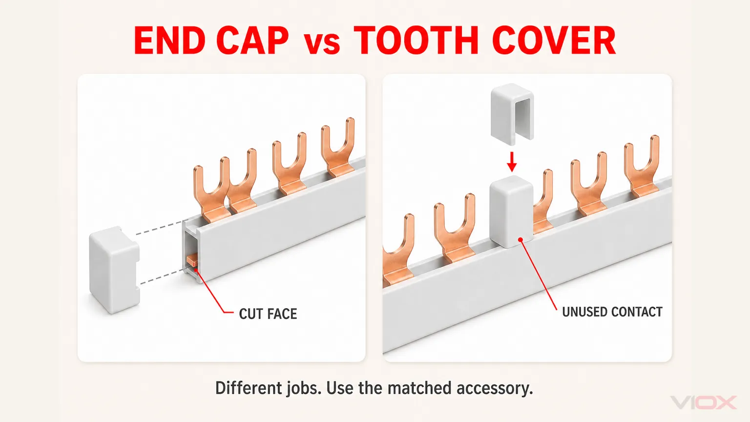
La face de coupe exposée est normalement protégée par l'embout spécifié pour ce système de jeu de barres. Faites correspondre l'embout à la famille de produits, au profil du conducteur, à la configuration des pôles et aux dimensions de la gaine.
Insérez l'embout dans sa position documentée sans forcer ni le modifier. Un embout correctement installé doit :
- recouvrir entièrement la face de coupe du conducteur ;
- reposer contre le corps isolé du jeu de barres comme prévu ;
- rester fixé sans se fendre ni se déformer ;
- éviter toute interférence avec le disjoncteur, l'enveloppe ou la barrière adjacent(e) ; et
- préserver la protection contre les contacts et le dispositif d'isolation requis pour l'assemblage terminé.
Certains systèmes de jeux de barres nécessitent des embouts aux deux extrémités ; d'autres fournissent une extrémité finie en usine et ne nécessitent une protection qu'à l'endroit où la barre a été coupée. Suivez le dessin technique du produit plutôt que d'appliquer une règle unique à chaque modèle.
Pourquoi le ruban isolant électrique ne constitue pas un substitut
Le ruban isolant peut se déplacer, se desserrer, se déchirer sur une bavure ou créer une épaisseur incontrôlée. Il ne garantit pas que les lignes de fuite, les distances d'isolement, la rétention ou la protection contre les contacts directs ont été rétablies. La gaine thermorétractable générique présente des limites similaires et peut générer de la chaleur lors de l'installation.
Utilisez du ruban, de la gaine thermorétractable, du composé de moulage ou toute autre alternative uniquement lorsque le fabricant du jeu de barres ou la procédure d'assemblage vérifiée définit explicitement cette méthode. “ Aucun cuivre visible ” n'est pas, en soi, la preuve d'un système d'isolation acceptable.
9. Protéger les dents sous tension inutilisées
Un embout recouvre la face coupée ; il ne couvre pas les contacts inutilisés le long de la barre. Si une dent sous tension reste en dehors d'une borne de disjoncteur, utilisez le cache-dent, le capuchon de protection ou la barrière spécifié — ou révisez la longueur de coupe — conformément aux instructions du système.
Ne qualifiez pas la rangée terminée de « protégée contre les contacts directs » (finger-safe) simplement parce que le conducteur principal possède une gaine en plastique. Les dents, les bornes d'alimentation, les contacts inutilisés et les extrémités coupées peuvent rester accessibles tant que les dispositifs, capots, barrières et enveloppes appropriés ne sont pas installés.
Réinstallation et vérification du peigne de raccordement
10. Remonter le jeu de barres sans forcer sur les dents
Alignez chaque contact avec sa borne prévue avant d'appliquer une pression. La barre doit reposer uniformément sur toute la rangée. N'utilisez pas les vis des bornes pour forcer l'alignement d'un peigne de raccordement incliné.
Vérifier que :
- chaque broche ou fourche pénètre dans la position de borne compatible ;
- l'isolation ne maintient pas un contact à l'extérieur de la borne ;
- aucune dent n'est tordue, décalée ou partiellement insérée ;
- l'embout de protection n'empêche pas l'insertion complète ;
- la séquence phase et neutre correspond au schéma ; et
- les positions sous tension inutilisées sont protégées.
Serrez chaque borne en utilisant la méthode et le couple de serrage indiqués par le fabricant de l'appareil. Il n'existe pas de valeur de couple universelle sûre pour toutes les combinaisons de disjoncteurs (MCB) et de peignes de raccordement.
Terminer la vérification de l'assemblage
Avant la mise sous tension, appliquer la procédure d'inspection et d'essai requise pour le tableau de distribution terminé. Le cas échéant, vérifier :
- les références correctes des appareils et des jeux de barres ;
- la continuité et l'ordre des phases ;
- la résistance d'isolement ou la vérification diélectrique selon la procédure d'assemblage approuvée ;
- les distances d'isolement spécifiées par rapport à l'enveloppe, au bornier de neutre, au bornier de terre de protection et aux autres parties conductrices ;
- le serrage correct des bornes et la bonne insertion des conducteurs ;
- l'absence de copeaux de cuivre, de visserie desserrée et d'isolant endommagé ;
- installation des embouts, des caches-dents et des barrières ; et
- couvercles de coffret et protection d'accès corrects.
Ne considérez pas un test de continuité réussi comme la preuve que la connexion présente une surface de contact ou une performance thermique suffisante. Une dent partiellement engagée peut conduire le courant lors d'un test à faible intensité tout en surchauffant en service.
Préparation des extrémités : correcte vs incorrecte
| Point d'inspection | État acceptable | Rejeter ou corriger |
|---|---|---|
| Autorisation de coupe | Une documentation produit précise permet de réduire | Le modèle est à longueur fixe, il est interdit de le couper ou de le modifier sans documentation |
| Face de coupe | Équerre, lisse et exempte de bavures libres | Écrasé, incliné, déchiré ou présentant des bavures tranchantes |
| Isolation | Intact le long de la barre sans fissure longitudinale | Fendu, brûlé, raboté sans instruction ou desserré |
| Dents | Droit, propre et correctement espacé | Plié, tordu, limé ou partiellement coupé |
| Embout de protection | Pièce conforme, entièrement insérée et mécaniquement stable | Embout générique, mauvais ajustement, embout fissuré ou face de coupe exposée |
| Contacts inutilisés | Protégés par des capots spécifiés ou retirés selon une longueur de coupe approuvée | Dent sous tension accessible laissée à découvert |
| Mise en place de l'appareil | Chaque dent pénètre entièrement dans la borne compatible prévue | La dent est inclinée, à l'extérieur de la cage ou serrée uniquement sur un bord |
| Propreté | Aucune particule conductrice ne subsiste | Présence de copeaux de cuivre dans les bornes ou le boîtier |
Erreurs courantes lors de la découpe des peignes d'alimentation
Découpe avant vérification de la référence du catalogue
La similitude visuelle ne prouve pas que deux jeux de barres partagent les mêmes règles de modification. Confirmez d'abord la référence exacte, en particulier lorsque l'homologation du produit ou la documentation d'assemblage doit être respectée.
Mesurer à partir de la largeur du coffret au lieu des positions de contact
Cela peut laisser une dent sous tension supplémentaire, supprimer un contact nécessaire ou décaler la séquence de phase prévue. Mesurez à partir de la rangée de dispositifs finale et du schéma approuvé.
Couper le jeu de barres alors qu'il est installé
Cela peut projeter des limailles conductrices dans les dispositifs de protection, endommager les bornes et exposer l'opérateur à des risques électriques et mécaniques. Retirez la pièce hors tension avant de procéder à la coupe.
Utiliser des outils de coupe qui écrasent le conducteur
Une coupe rapide n'est pas nécessairement une coupe maîtrisée. La déformation peut empêcher la mise en place de l'embout de protection et fissurer l'isolant au-delà de la face de coupe visible.
Monter un embout de protection sans ébavurer
Une arête vive en cuivre peut couper l'embout ou l'empêcher de rester dans sa position prévue. Ébavurez et nettoyez d'abord.
Laisser une dent inutilisée exposée
L'extrémité coupée peut être protégée pendant qu'un autre contact reste sous tension et accessible. Les embouts et les protections de dents remplissent des fonctions différentes.
Mélanger des gammes de jeux de barres et de disjoncteurs après la coupe
Le raccourcissement ne rend pas un jeu de barres incompatible compatible. La forme (broche ou fourche), le pas, l'épaisseur, la profondeur d'insertion et la conception des bornes doivent toujours correspondre.
Normes et limites du fabricant
CEI 61439-3:2024 définit les exigences pour les tableaux de distribution destinés à être utilisés par des personnes ordinaires dans le cadre de son champ d'application. Il s'applique à l'assemblage terminé ; ce n'est pas une instruction de coupe universelle pour chaque jeu de barres à peigne pour disjoncteurs modulaires (MCB).
Les fabricants de jeux de barres et d'appareils définissent si un produit particulier peut être raccourci, quels accessoires sont nécessaires et comment la pièce modifiée peut être utilisée. Le constructeur de tableaux doit également préserver l'agencement d'assemblage vérifié, les règles de câblage applicables et les exigences locales en matière de sécurité au travail.
Ne transférez pas une méthode de coupe, une référence d'embout ou une déclaration d'approbation d'une gamme de jeux de barres à une autre. Même les produits d'un même fabricant peuvent utiliser des sections de conducteur, des profils de gaine et des systèmes de protection d'extrémité différents.
Liste de contrôle pour la réception finale
Ne pas libérer le jeu de barres modifié pour l'installation tant que chaque point applicable n'est pas confirmé :
- □ Modèle exact de jeu de barres vérifié comme étant découpable
- □ Série de disjoncteur, interface à broche/fourche et pas confirmés
- □ Séquence des pôles et des phases vérifiée par rapport au schéma
- □ Coupe effectuée à la position approuvée avec l'outil approuvé
- □ Face de coupe équarrie, lisse et ébavurée
- □ Dents et isolation intactes
- □ Tous les débris conducteurs ont été retirés
- □ Embout de protection correctement mis en place
- □ Dents sous tension inutilisées protégées
- □ Peigne d'alimentation entièrement inséré dans chaque borne compatible
- □ Serrage des bornes effectué conformément aux instructions de l'appareil
- □ Inspection du tableau terminé et essais requis validés
Foire Aux Questions
Est-il possible de couper à longueur tous les peignes d'alimentation pour disjoncteurs ?
Non. Certains produits sont sécables, tandis que d'autres sont fournis uniquement dans des longueurs fixes approuvées. Vérifiez la référence exacte du catalogue et les instructions d'installation. Ne déduisez pas l'autorisation de couper à partir de l'apparence ou d'un autre produit de la même gamme.
Quel est le meilleur outil pour couper un peigne de raccordement ?
Utilisez l'outil spécifié pour le produit exact. Certaines instructions du fabricant préconisent l'utilisation d'une scie suivie d'un limage ; d'autres systèmes peuvent utiliser une pince coupante dédiée. L'outil doit permettre une coupe contrôlée sans écraser le conducteur, fissurer l'isolant ou tordre les dents adjacentes.
Puis-je couper un peigne de raccordement avec une pince coupante latérale ?
Non, sauf si le fabricant autorise spécifiquement cette méthode. Les pinces coupantes latérales et les coupe-boulons déforment généralement le conducteur et l'isolant au lieu de produire l'extrémité droite et lisse nécessaire à l'ajustement d'un embout de protection.
Un peigne de raccordement coupé nécessite-t-il toujours un embout de protection ?
L'extrémité coupée exposée nécessite normalement l'embout de protection correspondant ou la protection spécifique définie par le système du produit. Suivez scrupuleusement les instructions. Une extrémité finie en usine peut déjà être protégée, contrairement à une face venant d'être coupée.
La gaine thermorétractable peut-elle remplacer un embout de protection pour peigne de raccordement ?
Uniquement si le fabricant ou la procédure d'assemblage vérifiée l'autorise explicitement. Une gaine thermorétractable générique ne reproduit pas automatiquement l'ajustement, la rétention, la distance d'isolement ou la fonction de protection contre les contacts directs de l'embout d'origine.
Où doit-on couper un peigne d'alimentation triphasé ?
Coupez-le uniquement à l'endroit autorisé par le schéma du produit et la disposition réelle de l'appareil. Confirmez la séquence de phase répétitive et chaque pôle connecté avant de marquer. Il n'existe pas de règle universelle “ couper après chaque troisième dent ” qui s'applique à toutes les configurations de disjoncteurs modulaires (MCB), interrupteurs différentiels (RCCB) et disjoncteurs différentiels (RCBO).
Puis-je couper le peigne d'alimentation sans le retirer des disjoncteurs ?
Non. Isolez et vérifiez que l'assemblage est hors tension, puis retirez le peigne. Couper une barre installée risque de faire pénétrer des débris conducteurs dans les appareils, d'entraîner des dommages mécaniques et une exposition dangereuse.
Comment les dents inutilisées d'un peigne d'alimentation doivent-elles être isolées ?
Utilisez les caches-dents ou les capuchons de protection spécifiés pour ce système de peigne, ou raccourcissez la barre en utilisant une méthode approuvée. Un embout de protection protège la face coupée mais ne protège pas automatiquement les dents inutilisées le long de la barre.
Les peignes d'alimentation VIOX peuvent-ils être coupés ?
L'autorisation de coupe dépend du modèle VIOX exact, du schéma et de la configuration commandée. Avant toute modification, confirmez la série du peigne, la disposition des pôles, la géométrie des contacts, la longueur et les accessoires de protection d'extrémité requis auprès de VIOX ou de la documentation produit fournie.
Recommandation finale
Un peigne de raccordement correctement raccourci n'est pas simplement une barre longue que l'on coupe. Il s'agit d'un composant de distribution modifié dont le schéma de contact, l'isolation, la protection d'extrémité et la compatibilité doivent rester maîtrisés.
Utilisez la séquence suivante : Confirmez qu'il est sécable, cartographiez la rangée d'appareils, coupez d'équerre, ébavurez et nettoyez, installez l'embout de protection adapté, protégez les dents inutilisées, puis vérifiez l'assemblage terminé. Si la règle de coupe exacte ou l'accessoire ne peut être confirmé, utilisez la longueur d'usine correcte ou demandez une configuration adaptée plutôt que d'improviser.
Pour la correspondance des produits, consultez le VIOX gamme de peignes de raccordement pour disjoncteurs modulaires (MCB) à broches et à fourches et soumettez la série de disjoncteurs, le type de borne, la disposition des pôles, le pas, la longueur requise, l'arrangement des phases et la documentation du marché cible.
Sources
- Gamme de peignes de raccordement pour disjoncteurs modulaires VIOX.
- Guide de sélection des jeux de barres et peignes de raccordement VIOX pour disjoncteurs modulaires.
- Schneider Electric — Les peignes de raccordement Can Multi 9 C60BP peuvent-ils être coupés à n'importe quelle longueur souhaitée ?.
- Schneider Electric — Fiche d'instructions du tableau de répartition Easy9 NVE10739.
- ABB — Peignes de raccordement PS…CB et accessoires.
- IEC 61439-3:2024 — Tableaux de répartition destinés à être utilisés par des personnes ordinaires.