এই পৃষ্ঠায়
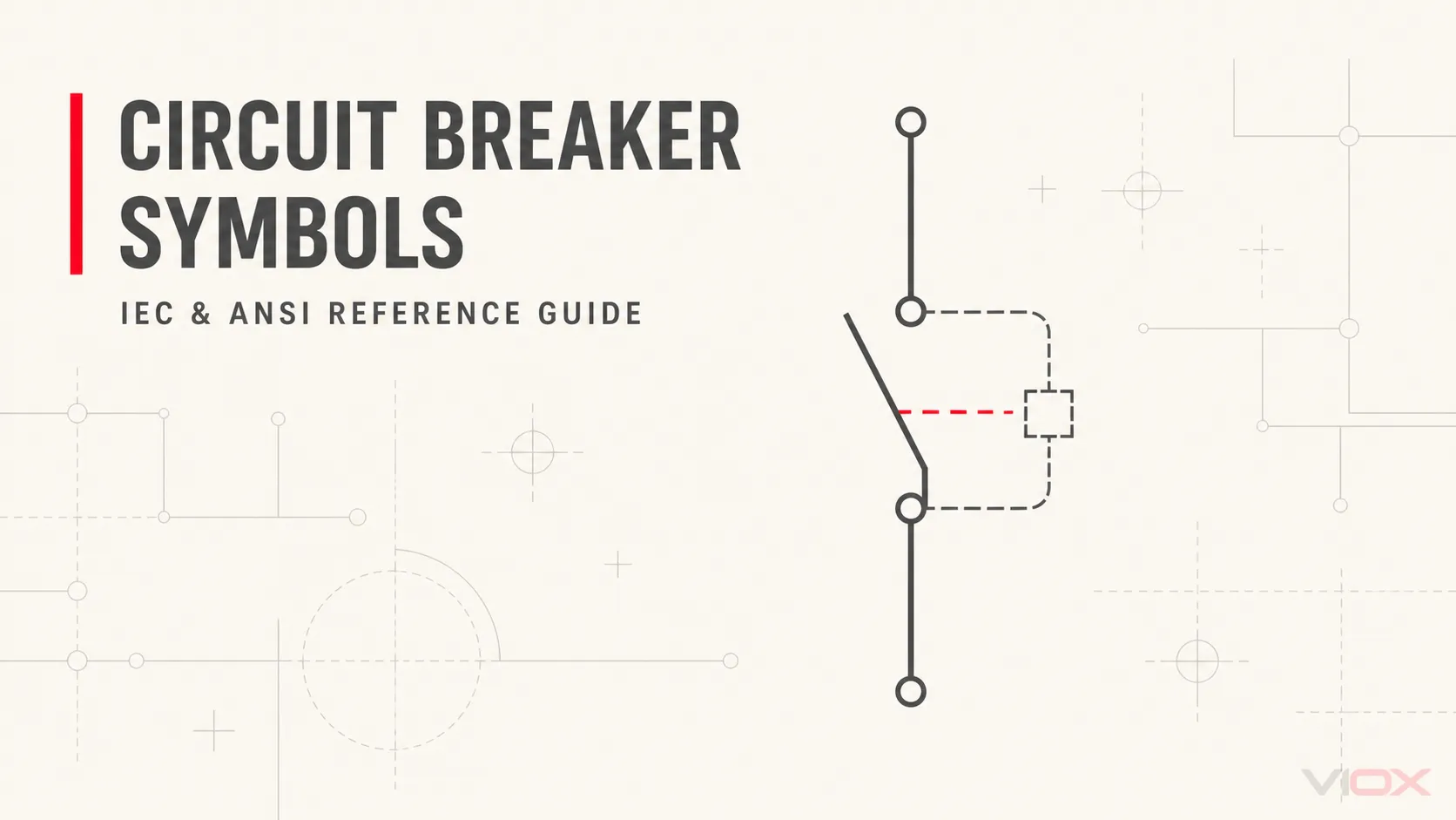
একটি সার্কিট ব্রেকার প্রতীক বৈদ্যুতিক ড্রয়িংয়ে একটি সুরক্ষামূলক সুইচিং ফাংশন নির্দেশ করে। প্রতিটি ড্রয়িংয়ের জন্য সঠিক এমন কোনো একক প্রতীক নেই: এর উপস্থাপনা প্রতীক পদ্ধতি, ডায়াগ্রামের ধরন এবং প্রজেক্ট লিজেন্ডের ওপর নির্ভর করে।.
শুধুমাত্র গ্রাফিক দেখে এটি শনাক্ত করা সম্ভব নাও হতে পারে যে ব্রেকারটি এমসিবি (MCB), এমসিসিবি (MCCB), এসিবি (ACB), ভিসিবি (VCB) নাকি এসএফ৬ (SF6) সার্কিট ব্রেকার। প্রকৌশলীরা প্রায়শই একটি বেস সার্কিট ব্রেকার প্রতীকের সাথে ডিভাইসের ট্যাগ, পোল সংখ্যা, ভোল্টেজ ক্লাস, প্রোটেকশন ফাংশন বা ইকুইপমেন্ট লেবেল ব্যবহার করেন। সর্বদা প্রতীক এবং এর সাথে থাকা টীকাগুলোকে একটি একক ইউনিট হিসেবে পড়ুন।.
সার্কিট ব্রেকার প্রতীক রেফারেন্স চার্ট
নিচের চার্টটিতে সাধারণত দেখা যায় এমন ১৬টি ব্রেকার উপস্থাপনা এবং সংশ্লিষ্ট ড্রয়িং উপাদানগুলোকে একত্রিত করা হয়েছে। এটি একটি ব্যাখ্যা সহায়িকা, কোনো প্রজেক্টের জন্য নির্দিষ্ট প্রতীক লাইব্রেরি বা লিজেন্ডের বিকল্প নয়। ড্রয়িং সিস্টেম, ডায়াগ্রামের ধরন, ক্যাড (CAD) লাইব্রেরি, ইউটিলিটি কনভেনশন এবং প্রস্তুতকারকের নথিপত্রের ওপর ভিত্তি করে জ্যামিতিক আকৃতি ভিন্ন হতে পারে।.
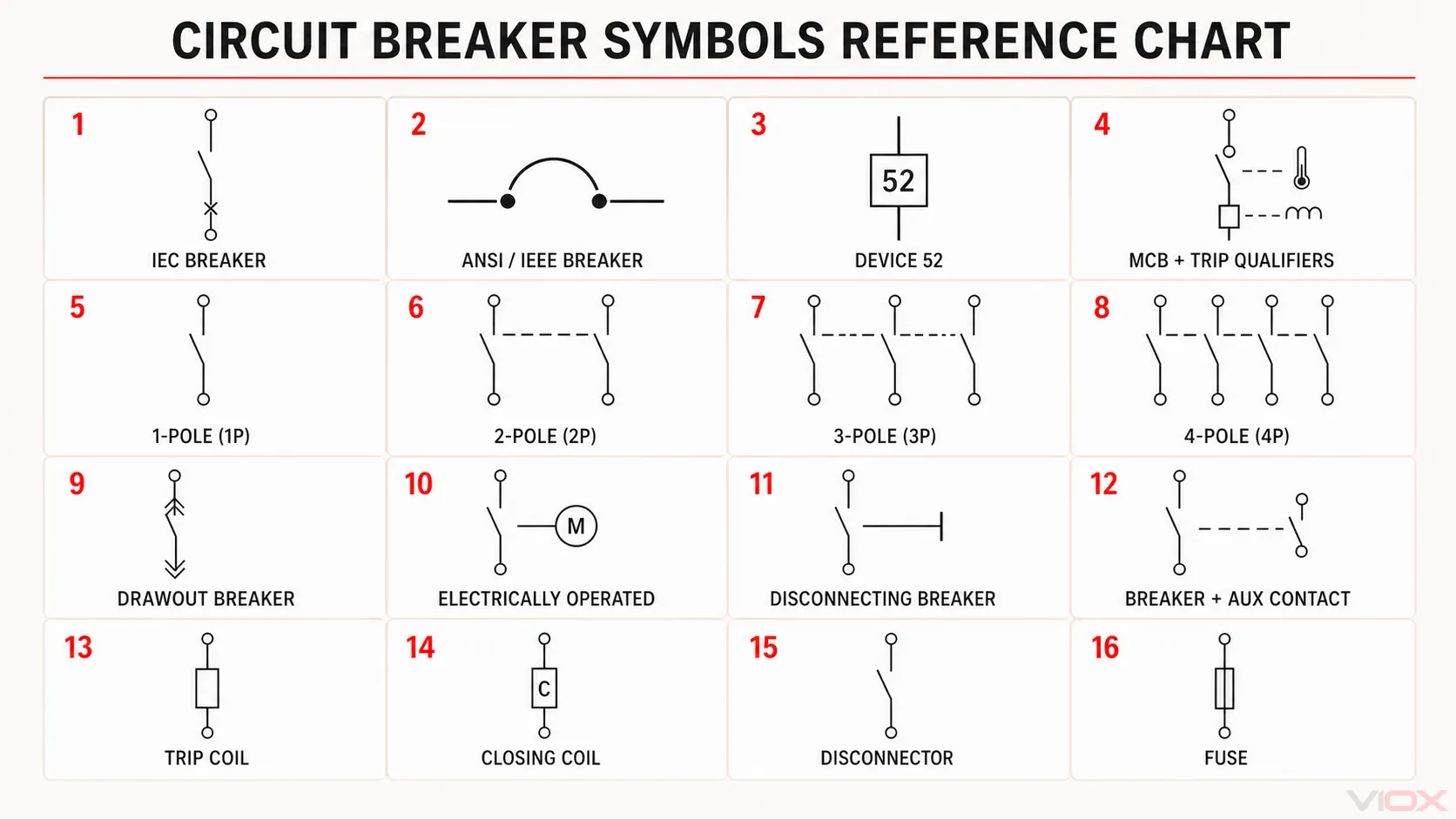
চার্টটি যেভাবে সাজানো হয়েছে
- মানদণ্ড-ভিত্তিক উপস্থাপনা এবং শনাক্তকারী (১–৪): একটি আইইসি (IEC) ভিত্তিক ব্রেকার ফাংশন, অনুভূমিক এএনএসআই/আইইইই (ANSI/IEEE) ব্রেকার উপস্থাপনা, ডিভাইস নম্বর ৫২ এবং থার্মাল ও ম্যাগনেটিক ট্রিপ কোয়ালিফায়ারসহ একটি এমসিবি (MCB)।.
- পোল কনফিগারেশন (৫–৮): ১পি (1P), ২পি (2P), ৩পি (3P) এবং ৪পি (4P) বিন্যাস। ড্যাশযুক্ত লাইনগুলো পোলগুলোর মধ্যে যান্ত্রিক সংযোগ নির্দেশ করে; এগুলো বৈদ্যুতিক পরিবাহী নয়।.
- গঠন এবং অপারেটিং ফাংশন (৯–১২): ড্র-আউট, বৈদ্যুতিকভাবে চালিত, ডিসকানেক্টিং এবং ব্রেকার-প্লাস-অক্সিলিয়ারি-কন্টাক্ট উপস্থাপনা। এই বৈশিষ্ট্যগুলো মূল প্রতীকের পাশে অথবা ক্রস-রেফারেন্সের মাধ্যমে অন্য কোনো ড্রয়িং শিটে দেখানো হতে পারে।.
- কন্ট্রোল এবং পার্শ্ববর্তী ডিভাইস (১৩–১৬): ট্রিপ কয়েল, ক্লোজিং কয়েল, ডিসকানেক্টর এবং ফিউজ। শেষের দুটি অন্তর্ভুক্ত করা হয়েছে কারণ এগুলো প্রায়শই সার্কিট ব্রেকারের সাথে গুলিয়ে ফেলা হয়, যদিও এগুলো ব্রেকারের ধরন নয়।.
দ্রুত শনাক্তকরণ টেবিল
| ড্রয়িং আইটেম | ড্রয়িংটি সাধারণত যা প্রকাশ করে | কী যাচাই করতে হবে |
|---|---|---|
| সাধারণ সার্কিট ব্রেকার | একটি সুইচিং ডিভাইস যা নির্দিষ্ট শর্তে স্বয়ংক্রিয়ভাবে বিদ্যুৎ প্রবাহ বিচ্ছিন্ন করতে সক্ষম | সিম্বল স্ট্যান্ডার্ড, ডিভাইস ট্যাগ, রেটিং এবং সুরক্ষা নোট |
| সিঙ্গেল-পোল ব্রেকার | একটি সুরক্ষিত পোল বা ডায়াগ্রামে প্রদর্শিত একটি পোল | ড্রয়িংটি সিঙ্গেল-লাইন নাকি মাল্টি-লাইন |
| মাল্টি-পোল ব্রেকার | যান্ত্রিকভাবে সংযুক্ত পোল, যা প্রায়শই পুনরাবৃত্ত কন্টাক্ট বা পোল লেবেল দ্বারা চিহ্নিত করা হয় | 2P, 3P, 4P, 1P+N বা 3P+N কনফিগারেশন |
| MCB | সাধারণত একটি ব্রেকার প্রতীক যার সাথে MCB বা QF-স্টাইলের ডিভাইসের রেফারেন্স থাকে | রেটেড কারেন্ট, ট্রিপ কার্ভ, ব্রেকিং ক্যাপাসিটি এবং পণ্যের মান (স্ট্যান্ডার্ড) |
| MCCB | সাধারণত একটি ব্রেকার প্রতীক যা MCCB, ফ্রেমের তথ্য বা ট্রিপ-ইউনিট ডেটা দ্বারা চিহ্নিত করা হয় | ফ্রেম সাইজ, ট্রিপ ইউনিট এবং ইন্টারাপ্টিং রেটিং |
| এসিবি | প্রায়শই একটি ACB লেবেল, ড্র-আউট নোটেশন বা সুইচগিয়ার রেফারেন্স দ্বারা চিহ্নিত করা হয় | ফিক্সড বা ড্র-আউট কনস্ট্রাকশন এবং কন্ট্রোল সার্কিট রেফারেন্স |
| VCB | সাধারণত VCB টেক্সট বা মিডিয়াম-ভোল্টেজ ইকুইপমেন্ট ট্যাগ দ্বারা চিহ্নিত করা হয় | ভোল্টেজ ক্লাস, ট্রাক পজিশন এবং প্রজেক্ট লিজেন্ড |
| SF6 সার্কিট ব্রেকার | সাধারণত SF6 বা হাই-ভোল্টেজ ইকুইপমেন্ট লেবেল দ্বারা চিহ্নিত করা হয় | ইকুইপমেন্ট টেকনোলজি এবং সাবস্টেশন ড্রয়িং কনভেনশন |
| GFCI বা AFCI ব্রেকার | প্রজেক্ট-নির্দিষ্ট টেক্সট লেবেল বা কোয়ালিফায়ারসহ একটি ব্রেকার সিম্বল | কোনো একটি সর্বজনীন গ্রাফিক ধরে নেবেন না; লিজেন্ড চেক করুন |
| আরসিসিবি (RCCB) অথবা আরসিবিও (RCBO) | ব্রেকার বা সুইচিং-ডিভাইস রিপ্রেজেন্টেশন এবং রেসিডুয়াল-কারেন্ট আইডেন্টিফিকেশনের সমন্বয় | ডিভাইসের কার্যকারিতা, ওভারকারেন্ট প্রোটেকশন এবং আঞ্চলিক পরিভাষা |
| মোটর-চালিত ব্রেকার | অপারেটিং মেকানিজম বা মোটর-কন্ট্রোল নোটেশনের সাথে যুক্ত ব্রেকার সিম্বল | কন্ট্রোল পাওয়ার, ক্লোজ কয়েল, ট্রিপ কয়েল এবং ইন্টারলকস |
| অক্সিলিয়ারি বা অ্যালার্ম কন্টাক্ট | ট্যাগ বা ক্রস-রেফারেন্সের মাধ্যমে ব্রেকারের সাথে যুক্ত একটি পৃথক কন্টাক্ট | স্বাভাবিক অবস্থা, টার্মিনাল নম্বর এবং প্রস্তুতকারকের ডায়াগ্রাম |
সবচেয়ে নির্ভরযোগ্য শনাক্তকরণ চারটি উপাদানের সম্মিলিত ব্যবহারের মাধ্যমে পাওয়া যায়: গ্রাফিক প্রতীক, ডিভাইসের ট্যাগ, পার্শ্ববর্তী রেটিং এবং ড্রয়িং লিজেন্ড.
আইইসি (IEC) বনাম এএনএসআই (ANSI) সার্কিট ব্রেকার প্রতীক
আইইসি (IEC) গ্রাফিক্যাল প্রতীক
আইইসি 60617 এটি ইলেকট্রোটেকনিক্যাল ডায়াগ্রামে ব্যবহৃত গ্রাফিক্যাল প্রতীকের জন্য অফিসিয়াল আইইসি (IEC) ডেটাবেস। এটি বর্তমানের স্বতন্ত্র কাগজের নথির পরিবর্তে একটি রক্ষণাবেক্ষণকৃত ডেটাবেস। এই ডেটাবেসে প্রতীকের শিরোনাম, গ্রাফিক্যাল উপস্থাপনা, রেফারেন্স নম্বর, অ্যাপ্লিকেশন নোট এবং প্রতীকের মধ্যে সম্পর্ক অন্তর্ভুক্ত রয়েছে।.
একটি আইইসি (IEC)-ভিত্তিক ড্রয়িংয়ে একটি সুইচিং কন্টাক্ট এবং এক বা একাধিক কোয়ালিফাইং প্রতীকের সমন্বয়ে ব্রেকারের উপস্থাপনা তৈরি করা হতে পারে। যে ফাংশনটি বোঝানো হচ্ছে এবং ডায়াগ্রামের ধরনের ওপর ভিত্তি করে এর সঠিক রূপ পরিবর্তিত হতে পারে। এই কারণে, একটি ড্রয়িং থেকে কপি করা সরলীকৃত প্রতীককে স্বয়ংক্রিয়ভাবে একমাত্র আইইসি (IEC) সার্কিট ব্রেকার প্রতীক হিসেবে গণ্য করা উচিত নয়।.
এএনএসআই (ANSI) এবং উত্তর আমেরিকান ড্রয়িং
উত্তর আমেরিকার অঙ্কনগুলোতে IEEE/ANSI অনুশীলন, কোম্পানির ড্রাফটিং স্ট্যান্ডার্ড, ইউটিলিটি কনভেনশন বা CAD লাইব্রেরি থেকে প্রাপ্ত প্রতীক এবং ডিভাইসের নাম ব্যবহার করা হতে পারে।. IEEE/ANSI 315-1975 বর্তমানে IEEE দ্বারা শ্রেণীবদ্ধ করা হয়েছে ইনঅ্যাক্টিভ-রিজার্ভড (নিষ্ক্রিয়-সংরক্ষিত) হিসেবে, যদিও এর প্রতীকগুলো এখনও পুরনো নথিপত্র এবং প্রতিষ্ঠিত অঙ্কন ব্যবস্থায় দেখা যায়।.
পাওয়ার-সিস্টেমের অঙ্কনগুলোতে ডিভাইসের নম্বরও ব্যবহার করা হতে পারে। উদাহরণস্বরূপ, 52 সুরক্ষা এবং নিয়ন্ত্রণ নথিপত্রে একটি এসি (AC) সার্কিট ব্রেকার শনাক্ত করতে সাধারণত ব্যবহৃত হয়। ডিভাইসের নম্বর একটি শনাক্তকারী মাত্র, এটি ড্রয়িং লিজেন্ড বা ব্রেকারের স্পেসিফিকেশনের বিকল্প নয়।.
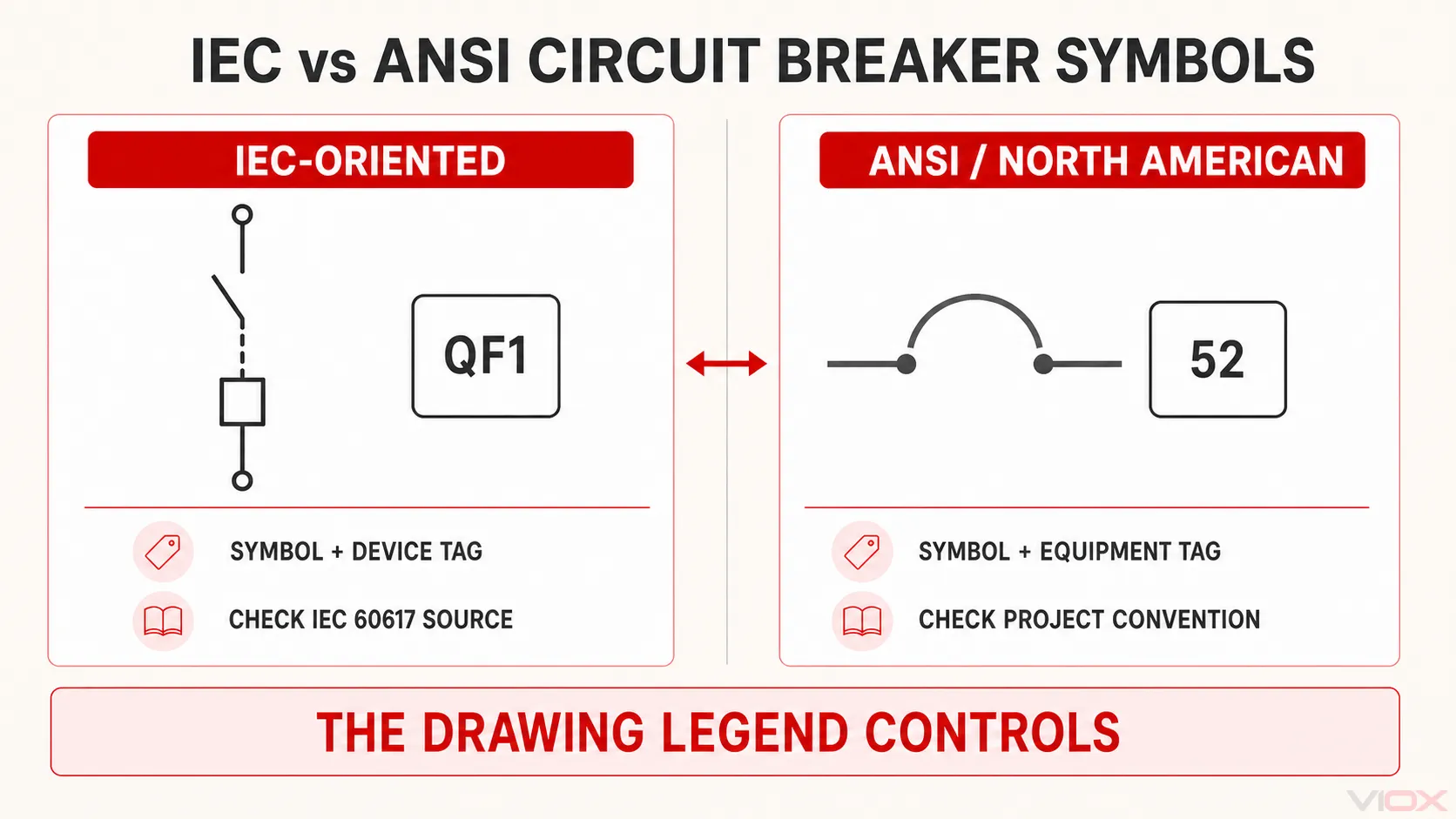
| তুলনার বিষয় | IEC-ভিত্তিক অঙ্কন | ANSI/উত্তর আমেরিকান অঙ্কন |
|---|---|---|
| প্রাথমিক রেফারেন্স | IEC 60617 ডেটাবেস | প্রজেক্ট বা ইউটিলিটি কনভেনশন; লিগ্যাসি IEEE/ANSI 315 প্রতীক থাকতে পারে |
| ডিভাইস শনাক্তকরণ | প্রতীক এবং ক্লাস/রেফারেন্স ডেজিগনেশন ও প্রজেক্ট ট্যাগ | প্রতীক এবং ইকুইপমেন্ট ট্যাগ বা ডিভাইস নম্বর |
| পরিবর্তনের সাধারণ উৎস | ফাংশন কোয়ালিফায়ার এবং ডায়াগ্রামের ধরন | ইউটিলিটি, প্রস্তুতকারক এবং প্রচলিত ড্রাফটিং কনভেনশন |
| সঠিক পাঠ পদ্ধতি | প্রজেক্টে ব্যবহৃত আইইসি (IEC) সিম্বল রেফারেন্স এবং লিজেন্ড যাচাই করুন | ড্রয়িং লিজেন্ড, ডিভাইসের তালিকা এবং প্রজেক্ট ড্রাফটিং স্ট্যান্ডার্ড যাচাই করুন |
সার্কিট ব্রেকার সিম্বল কীভাবে পড়তে হয়
1. ড্রয়িংয়ের ধরন শনাক্ত করুন
একটি সিঙ্গেল-লাইন ডায়াগ্রাম একটি মাল্টি-কন্ডাক্টর পাওয়ার সিস্টেমকে সরলীকৃত আকারে উপস্থাপন করে। একটি মাল্টি-লাইন স্কিম্যাটিক আলাদাভাবে পোল, অপারেটিং কয়েল, অক্সিলিয়ারি কন্টাক্ট এবং ইন্টারলক দেখাতে পারে। আর্কিটেকচারাল প্ল্যানে আবার ভিন্ন ধরনের নোটেশন ব্যবহার করা হতে পারে।.
প্রতিটি ড্রয়িং টাইপ থেকে একই পরিমাণ তথ্যের আশা করবেন না।.
2. প্রোটেক্টিভ সুইচিং ফাংশনটি খুঁজে বের করুন
প্রথমে সার্কিট ব্রেকারকে সাধারণ সুইচ, ডিসকানেক্টর বা ফিউজ থেকে আলাদা করুন। একটি সার্কিট ব্রেকার নির্দিষ্ট শর্তে স্বয়ংক্রিয়ভাবে বিদ্যুৎ সংযোগ বিচ্ছিন্ন করার পাশাপাশি সুইচিংয়ের কাজ করে। একটি ডিসকানেক্টর মূলত আইসোলেশন প্রদান করে, যেখানে একটি ফিউজ তার এলিমেন্ট গলিয়ে বিদ্যুৎ সংযোগ বিচ্ছিন্ন করে এবং অপারেশনের পর তা প্রতিস্থাপন করতে হয়।.
একটি প্রতীক পণ্যের সম্পূর্ণ গঠন প্রকাশ না করেই তার কার্যকারিতা দেখাতে পারে। রেটিং এবং সুরক্ষামূলক বৈশিষ্ট্যগুলো সাধারণত পার্শ্ববর্তী টেক্সট, ডিভাইস ট্যাগ, শিডিউল এন্ট্রি বা আলাদা স্পেসিফিকেশনে উল্লেখ থাকে।.
3. ডিভাইস ট্যাগ এবং অ্যানোটেশনগুলো পড়ুন
CB, MCB, MCCB, ACB, VCB, QF বা প্রজেক্ট-নির্দিষ্ট ইকুইপমেন্ট নম্বরের মতো লেবেলগুলো খুঁজুন। এরপর সংশ্লিষ্ট তথ্যগুলো দেখুন, যার মধ্যে থাকতে পারে:
- রেটেড কারেন্ট;
- সিস্টেম ভোল্টেজ;
- পোল সংখ্যা;
- ইন্টারাপ্টিং বা ব্রেকিং ক্যাপাসিটি;
- ট্রিপ-ইউনিট টাইপ বা প্রোটেকশন ফাংশন;
- ফিক্সড, প্লাগ-ইন, বা ড্র-আউট কনস্ট্রাকশন;
- নরমালি ওপেন, নরমালি ক্লোজড, বা নরমাল সার্ভিস পজিশন।.
এই সংক্ষিপ্ত রূপটি শুধুমাত্র ড্রয়িংয়ের নথিবদ্ধ কনভেনশনের মধ্যেই কার্যকর। উদাহরণস্বরূপ, কিউএফ (QF)-স্টাইল ট্যাগ কিছু আইইসি (IEC)-ভিত্তিক প্রজেক্টে সাধারণ হলেও এটিকে সর্বজনীন হিসেবে ধরে নেওয়া উচিত নয়।.
৪. পোল সংখ্যা নির্ধারণ করুন
একটি বিস্তারিত স্কিমেটিকে, লিঙ্কড কন্টাক্টগুলো দেখাতে পারে যে পোলগুলো একসাথে কাজ করে। একটি সিঙ্গেল-লাইন ডায়াগ্রামে, একটি লাইন সম্পূর্ণ থ্রি-ফেজ সার্কিটকে উপস্থাপন করতে পারে, তাই অঙ্কিত লাইনের সংখ্যা সবসময় প্রকৃত পোল সংখ্যা নির্দেশ করে না।.
১পি (1P), ২পি (2P), ৩পি (3P), ৪পি (4P), ১পি+এন (1P+N), বা ৩পি+এন (3P+N)-এর মতো লেবেল থেকে বিন্যাসটি নিশ্চিত করুন। একটি সুইচড নিউট্রাল মানেই স্বয়ংক্রিয়ভাবে ওভারকারেন্ট-প্রোটেক্টেড পোল নয়; পণ্যের ডকুমেন্টেশন এবং স্কিমেটিকে অবশ্যই এর কার্যকারিতা স্পষ্টভাবে উল্লেখ থাকতে হবে।.
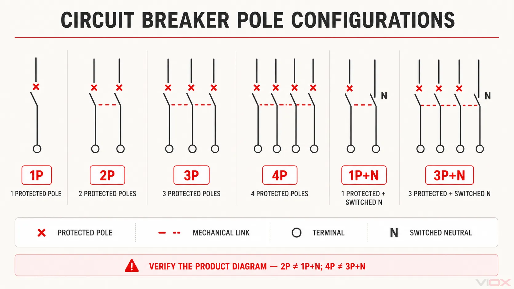
এই রিডিং রুলগুলো ব্যবহার করুন:
- একটি × কোয়ালিফায়ার এই চিত্রে একটি প্রোটেক্টেড পোলকে চিহ্নিত করে।.
- ক ড্যাশড লাইন কন্টাক্টগুলোর মধ্যে যান্ত্রিক সংযোগ নির্দেশ করে, বৈদ্যুতিক সংযোগ নয়।.
- একটি সাধারণ ১পি+এন বিন্যাসে, একটি ফেজ পোল সুরক্ষিত থাকে এবং নিউট্রাল পোলটি তার সাথে সুইচ করা হয়। একটি সাধারণ 3P+N এর বিবরণ বিন্যাসে, তিনটি ফেজ পোল সুরক্ষিত থাকে এবং নিউট্রালটি তাদের সাথে সুইচ করা হয়।.
- 2P স্বয়ংক্রিয়ভাবে 1P+N এর সমতুল্য নয়।, এবং 4P স্বয়ংক্রিয়ভাবে 3P+N এর সমতুল্য নয়।. ব্রেকারের মার্কিং এবং প্রস্তুতকারকের ডায়াগ্রাম থেকে যাচাই করুন কোন পোলগুলোতে ওভারকারেন্ট রিলিজ রয়েছে।.
ক্রস-রেফারেন্সগুলো অনুসরণ করুন।
ট্রিপ কয়েল, ক্লোজিং কয়েল, আন্ডারভোল্টেজ রিলিজ, শান্ট রিলিজ, অ্যালার্ম কন্টাক্ট এবং পজিশন কন্টাক্টগুলোকে মূল ব্রেকার প্রতীক থেকে দূরে আঁকা হতে পারে। ডিভাইসের ট্যাগ এবং গ্রিড রেফারেন্সের মিল এই উপাদানগুলোকে একই ফিজিক্যাল ব্রেকারের সাথে সংযুক্ত করে।.
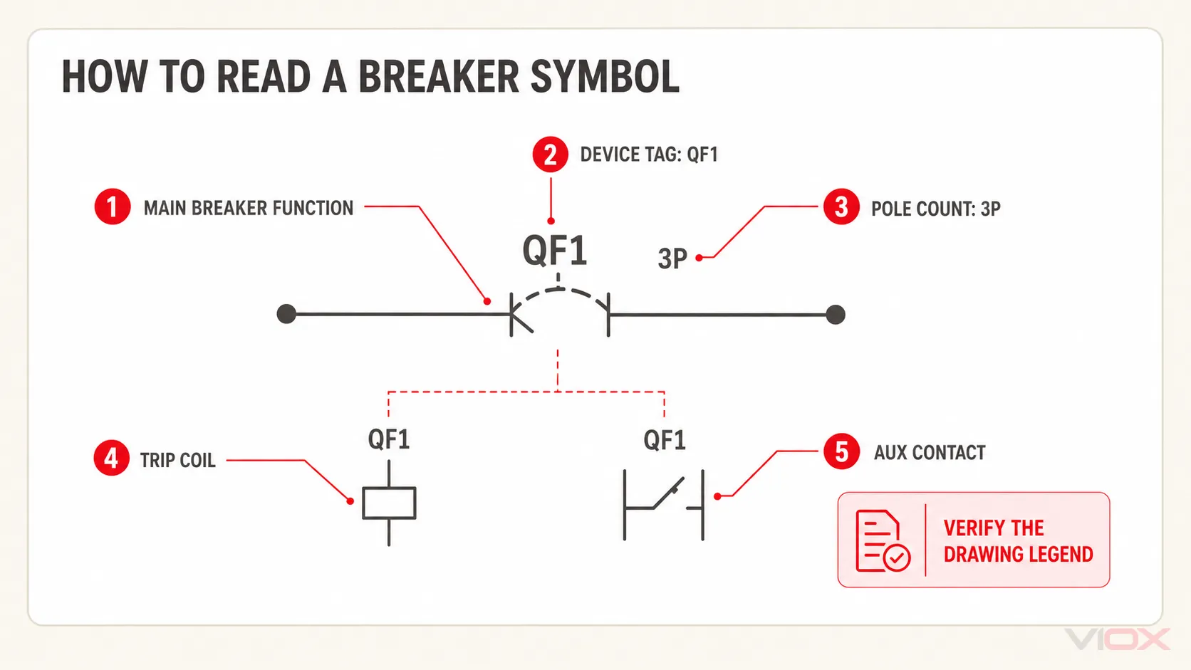
MCB, MCCB, ACB, VCB এবং SF6 ব্রেকারের প্রতীকসমূহ।
পণ্যের নাম সবসময় একটি অনন্য সর্বজনীন গ্রাফিক্যাল প্রতীক তৈরি করে না।.
MCB এবং MCCB প্রতীক
ক miniature circuit breaker (MCB) এবং একটি {"76":"molded case circuit breaker (MCCB)"} সিঙ্গেল-লাইন ডায়াগ্রামে একই বেস ব্রেকার ফাংশন ব্যবহার করা হতে পারে। পার্থক্যটি সাধারণত ডিভাইসের ট্যাগ, ফ্রেম বা কারেন্ট ডেটা, ট্রিপ-ইউনিট তথ্য এবং ইকুইপমেন্ট শিডিউলের মাধ্যমে চিহ্নিত করা হয়।.
শুধুমাত্র গ্রাফিক দেখে ট্রিপ কার্ভ, ব্রেকিং ক্যাপাসিটি বা প্রযোজ্য পণ্যের মান অনুমান করবেন না।.
ACB, VCB এবং SF6 সার্কিট ব্রেকার প্রতীক
এয়ার, ভ্যাকুয়াম এবং SF6 ব্রেকারের প্রযুক্তি বা ইন্টারাপ্টিং মাধ্যমকে বর্ণনা করে। কিছু ড্রয়িং লাইব্রেরিতে বিশেষ গ্রাফিক্স থাকে, তবে অনেক প্রজেক্টে একটি সাধারণ সার্কিট ব্রেকার প্রতীকের পরে ACB, VCB বা SF6 লেবেল ব্যবহার করা হয়।.
ভ্যাকুয়াম সার্কিট ব্রেকারের ক্ষেত্রে, মৌলিক প্রতীকের চেয়ে আশেপাশের প্রেক্ষাপট অনেক বেশি তথ্যবহুল হয়: মিডিয়াম-ভোল্টেজ সুইচগিয়ার রেফারেন্স, ট্রাক পজিশন, আর্থিং সুইচ, প্রোটেকশন রিলে এবং কন্ট্রোল-সার্কিট ক্রস-রেফারেন্স ডিভাইসটি নিশ্চিত করতে সাহায্য করে।.
GFCI, AFCI, RCCB এবং RCBO নোটেশন
GFCI এবং AFCI সুরক্ষা প্রয়োজনীয়তা প্রতিটি ইলেকট্রিক্যাল প্ল্যানের জন্য একটি সর্বজনীনভাবে স্বীকৃত ব্রেকার গ্রাফিক তৈরি করে না। ডিজাইনাররা সাধারণত একটি টেক্সট লেবেল, সংক্ষিপ্ত রূপ, কোয়ালিফায়ার বা প্যানেল-শিডিউল নোট যোগ করেন। প্রজেক্ট লিজেন্ডই এক্ষেত্রে চূড়ান্ত সিদ্ধান্ত প্রদান করে।.
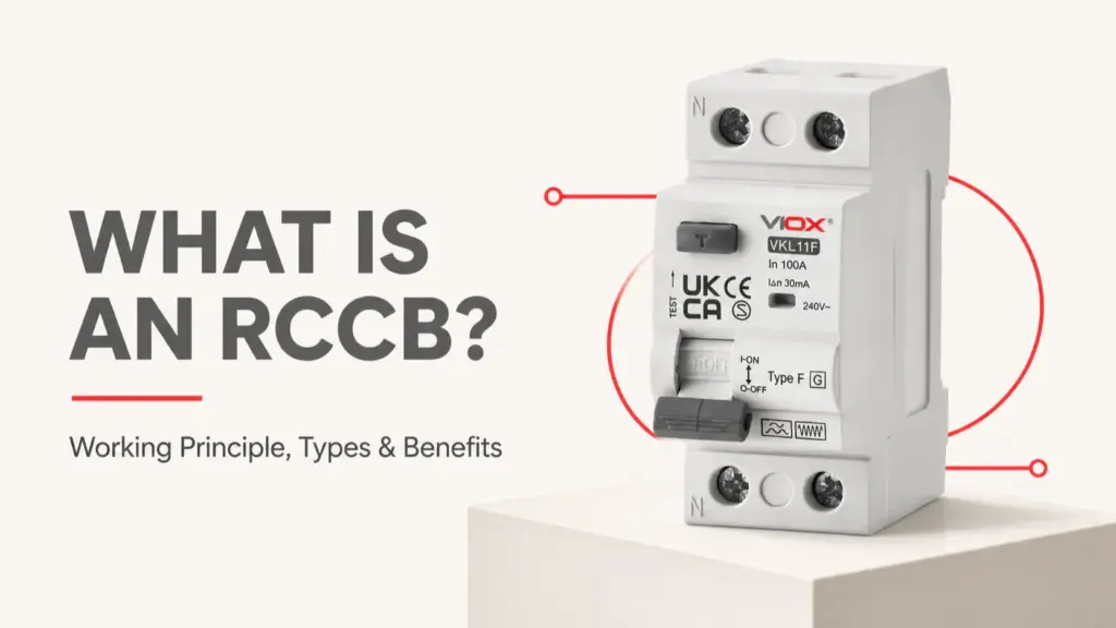
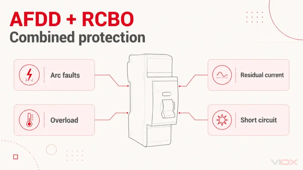
একই নিয়ম IEC-ভিত্তিক বাজারগুলোতে রেসিডুয়াল-কারেন্ট ডিভাইসের ক্ষেত্রেও প্রযোজ্য। একটি RCCB ইন্টিগ্রাল ওভারকারেন্ট প্রোটেকশন ছাড়া রেসিডুয়াল-কারেন্ট সুরক্ষা প্রদান করে, যেখানে একটি আরসিবিও রেসিডুয়াল-কারেন্ট এবং ওভারকারেন্ট সুরক্ষাকে একত্রিত করে। শুধুমাত্র অস্পষ্ট “RCD” লেবেলের ওপর নির্ভর না করে একটি ড্রয়িংয়ের মাধ্যমে সেই কার্যকরী পার্থক্যটি স্পষ্ট করা উচিত।.
সার্কিট ব্রেকার, ফিউজ, সুইচ এবং ডিসকানেক্টর প্রতীকসমূহ
| যন্ত্র | প্রধান কার্যাবলী যা নির্দেশিত হয় | সাধারণ ব্যাখ্যার ঝুঁকি |
|---|---|---|
| সার্কিট ব্রেকার | সুইচিং এবং স্বয়ংক্রিয় ফল্ট ইন্টারাপশন | এটিকে ম্যানুয়ালি চালিত সুইচ হিসেবে ভুল করা |
| ফিউজ | একটি পরিবর্তনযোগ্য উপাদানের মাধ্যমে ওভারকারেন্ট বাধা প্রদান | এটি ব্রেকারের মতো রিসেট করা যায় ধরে নিয়ে |
| সুইচ | নির্ধারিত ডিউটি অনুযায়ী কারেন্ট সংযোগ ও বিচ্ছিন্ন করা | এটি স্বয়ংক্রিয় ওভারকারেন্ট সুরক্ষা প্রদান করে ধরে নিয়ে |
| ডিসকানেক্টর বা আইসোলেটর | আইসোলেশন এবং একটি নির্দিষ্ট ডিসকানেকশন ফাংশন | এটি ফল্ট কারেন্ট বাধা দিতে পারে ধরে নিয়ে |
| সুইচ-ডিসকানেক্টর | ঘোষিত রেটিংয়ের মধ্যে সুইচিং এবং আইসোলেশন | এটিকে ওভারকারেন্ট সুরক্ষা ছাড়া একটি সার্কিট ব্রেকার হিসেবে গণ্য করা |
ডিভাইসের রেটিং এবং অনুমোদিত কার্যক্ষমতা নির্ধারণ করে সরঞ্জামের স্পেসিফিকেশন—দুটি প্রতীকের দৃশ্যমান সাদৃশ্য নয়।.
অক্সিলারি কন্টাক্ট এবং ট্রিপ কন্টাক্ট প্রতীকসমূহ
অক্সিলারি কন্টাক্টগুলো ব্রেকারের অবস্থা জানায় অথবা কন্ট্রোল লজিকের সাথে কাজ করে। অ্যালার্ম বা ট্রিপ-ইন্ডিকেশন কন্টাক্টগুলো কেবল একটি প্রোটেক্টিভ ট্রিপের পরেই তাদের অবস্থা পরিবর্তন করতে পারে। পজিশন কন্টাক্টগুলো ড্র-আউট সরঞ্জামের ওপেন, ক্লোজড, কানেক্টেড, টেস্ট বা ডিসকানেক্টেড অবস্থা নির্দেশ করতে পারে।.
টার্মিনাল নম্বরগুলো প্রস্তুতকারকের ডায়াগ্রামের সাথে মিলিয়ে যাচাই করতে হবে। একটি সাধারণ উদাহরণ হিসেবে, স্নাইডার ইলেকট্রিক (Schneider Electric)-এর ডকুমেন্টেশনে চিহ্নিত করা হয়েছে ৯৫–৯৬ হলো একটি নরমালি ক্লোজড ফল্ট-সিগন্যালিং কন্টাক্ট এবং ৯৭–৯৮ হলো একটি নরমালি ওপেন ফল্ট-সিগন্যালিং কন্টাক্ট নির্দিষ্ট ডিভাইসের ক্ষেত্রে। এই নম্বর পদ্ধতিটি প্রতিটি ব্রেকার অ্যাক্সেসরি বা প্রস্তুতকারকের ক্ষেত্রে সাধারণ নিয়ম হিসেবে ধরা উচিত নয়।.
অক্সিলিয়ারি কন্টাক্ট পড়ার সময়:
- কন্টাক্ট ট্যাগটিকে মূল ব্রেকারের সাথে মিলিয়ে নিন।.
- ড্রয়িংটি স্বাভাবিক, ডি-এনার্জাইজড নাকি সার্ভিস স্টেট নির্দেশ করছে তা নির্ধারণ করুন।.
- কন্টাক্টটি ব্রেকারের অবস্থান, মেকানিজমের অবস্থা নাকি প্রোটেক্টিভ ট্রিপ নির্দেশ করছে তা শনাক্ত করুন।.
- পণ্যের ওয়্যারিং ডায়াগ্রামে টার্মিনাল নম্বরগুলো যাচাই করুন।.
সার্কিট ব্রেকার প্রতীকের সাধারণ ভুলসমূহ
একটি প্রতীককে সর্বজনীন মনে করা
আইইসি (IEC), উত্তর আমেরিকান, ইউটিলিটি, প্রস্তুতকারক এবং প্রকল্প-নির্দিষ্ট কনভেনশন ভিন্ন হতে পারে। কোনো অর্থ নির্ধারণের আগে লিজেন্ড বা নির্দেশিকা দেখুন।.
শুধুমাত্র আকৃতি দেখে ব্রেকার প্রযুক্তি শনাক্ত করা
একটি VCB, ACB, বা SF6 ব্রেকার একটি সাধারণ সার্কিট ব্রেকার প্রতীক এবং সাথে টেক্সট আইডেন্টিফায়ার ব্যবহার করতে পারে। শুধুমাত্র প্রতীকের আকৃতি দেখে ইন্টারাপ্টিং মাধ্যমটি বোঝা সম্ভব নাও হতে পারে।.
গ্রাফিক থেকে রেটিং পড়া
কারেন্ট রেটিং, ভোল্টেজ, ব্রেকিং ক্যাপাসিটি, ট্রিপ কার্ভ এবং ট্রিপ সেটিংস সাধারণত অ্যানোটেশন, শিডিউল বা ডিভাইসের ডেটা থেকে আসে—মৌলিক ব্রেকার প্রতীক থেকে নয়।.
কোড প্রয়োজনীয়তাকে প্রতীকের মানদণ্ডের সাথে গুলিয়ে ফেলা
ইন্সটলেশন কোডগুলো নির্ধারণ করে যে কোথায় নির্দিষ্ট সুরক্ষা প্রয়োজন হতে পারে। এগুলো প্রতিটি প্রজেক্টের জন্য একটি সর্বজনীন CAD প্রতীক নির্ধারণ করে না। সুরক্ষার প্রয়োজনীয়তা এবং ড্রয়িং কনভেনশনগুলোকে আলাদা রাখুন।.
স্বাভাবিক অবস্থার কনভেনশন উপেক্ষা করা
কন্টাক্টগুলো প্রায়শই একটি নির্দিষ্ট স্বাভাবিক অবস্থায় দেখানো হয়, তবে সেই অবস্থাটি ড্রয়িংয়ের নিয়ম থেকে উল্লেখ বা বোঝা আবশ্যক। অপারেটিং স্টেট সম্পর্কে ভুল ধারণা ইন্টারলক বা অ্যালার্ম সার্কিটের ব্যাখ্যাকে বিপরীত করে দিতে পারে।.
সচরাচর জিজ্ঞাস্য
সার্কিট ব্রেকারের জন্য স্ট্যান্ডার্ড প্রতীক কী?
বিশ্বব্যাপী প্রতিটি ড্রয়িংয়ের জন্য কোনো একক গ্রাফিক নেই। আইইসি (IEC)-ভিত্তিক প্রকল্পগুলো IEC 60617 ডেটাবেস অনুসরণ করে, যেখানে উত্তর আমেরিকান এবং পুরোনো ড্রয়িংগুলোতে ভিন্ন কনভেনশন ব্যবহার করা হতে পারে। সর্বদা প্রজেক্ট লিজেন্ড এবং ড্রয়িং স্ট্যান্ডার্ড যাচাই করুন।.
আইইসি (IEC) সার্কিট ব্রেকার প্রতীক কী?
IEC 60617-এ ইলেকট্রোটেকনিক্যাল ডায়াগ্রামের জন্য গ্রাফিক্যাল প্রতীক এবং কোয়ালিফাইং এলিমেন্ট রয়েছে। ব্রেকারের সঠিক উপস্থাপনা নির্ভর করে এর কার্যকারিতা এবং ডায়াগ্রামের প্রেক্ষাপটের ওপর। সঠিক জ্যামিতি এবং রেফারেন্স নম্বরের জন্য অফিসিয়াল IEC 60617 ডেটাবেস অথবা লাইসেন্সপ্রাপ্ত, প্রজেক্ট-অনুমোদিত সিম্বল লাইব্রেরি ব্যবহার করুন।.
এমসিবি (MCB) প্রতীক কি এমসিসিবি (MCCB) প্রতীক থেকে আলাদা?
সবসময় নয়। একটি সিঙ্গেল-লাইন ডায়াগ্রামে একই মৌলিক ব্রেকার প্রতীক ব্যবহার করা হতে পারে এবং এমসিবি (MCB) বা এমসিসিবি (MCCB) ট্যাগ, রেটিং, ফ্রেমের তথ্য এবং ট্রিপ-ইউনিট ডেটা দিয়ে পণ্যগুলোকে আলাদা করা হয়।.
ভ্যাকুয়াম সার্কিট ব্রেকারের প্রতীক কী?
কিছু সিম্বল লাইব্রেরিতে বিশেষ উপস্থাপনা থাকে, তবে অনেক ড্রয়িংয়ে সাধারণ ব্রেকার প্রতীক ব্যবহার করে সেটিকে ভিসিবি (VCB) হিসেবে চিহ্নিত করা হয়। শুধুমাত্র আকৃতির ওপর নির্ভর না করে সরঞ্জামের ট্যাগ, ভোল্টেজ ক্লাস, সুইচগিয়ার প্রেক্ষাপট এবং লিজেন্ড যাচাই করুন।.
একটি জিএফসিআই (GFCI) ব্রেকার ড্রয়িংয়ে কীভাবে দেখানো হয়?
এর চিহ্ন ভিন্ন হতে পারে। এটি জিএফসিআই (GFCI), জিএফ (GF), প্রজেক্ট-নির্ধারিত কোয়ালিফায়ার বা প্যানেল-শিডিউল নোট দ্বারা চিহ্নিত করা যেতে পারে। ঢেউ খেলানো রেখা, গ্রাউন্ড মার্ক বা অন্য কোনো গ্রাফিক সব ড্রয়িংয়ে একই অর্থ বহন করে বলে ধরে নেবেন না।.
সার্কিট ব্রেকারের পাশে ৫২ (52) থাকার অর্থ কী?
পাওয়ার-সিস্টেম সুরক্ষা এবং নিয়ন্ত্রণ নথিপত্রে, ডিভাইস নম্বর ৫২ সাধারণত একটি এসি (AC) সার্কিট ব্রেকারকে নির্দেশ করে। সম্পূর্ণ ট্যাগটিতে অতিরিক্ত অক্ষর বা সংখ্যা থাকতে পারে যা অবস্থান, ভোল্টেজ লেভেল বা সরঞ্জামের ক্রম নির্দেশ করে।.
আমি কীভাবে একটি সার্কিট ব্রেকারকে ডিসকানেক্টর থেকে আলাদা করব?
একটি সার্কিট ব্রেকারে স্বয়ংক্রিয় ফল্ট-ইন্টারাপশন বা ত্রুটি বিচ্ছিন্ন করার ক্ষমতা থাকে। একটি ডিসকানেক্টর শুধুমাত্র আইসোলেশন বা সংযোগ বিচ্ছিন্ন করার কাজ করে এবং এটি স্বয়ংক্রিয়ভাবে ব্রেকারের সমতুল্য নয়। সিম্বল কোয়ালিফায়ার, ডিভাইস ট্যাগ, সরঞ্জামের স্পেসিফিকেশন এবং প্রজেক্ট লিজেন্ড পরীক্ষা করুন।.
চূড়ান্ত পাঠের নিয়ম
সার্কিট ব্রেকারের সিম্বলকে সম্পূর্ণ স্পেসিফিকেশন হিসেবে না ধরে শুরুর বিন্দু হিসেবে বিবেচনা করুন। একটি নির্ভরযোগ্য ব্যাখ্যার জন্য সিম্বলের সাথে ড্রয়িংয়ের ধরন, ইকুইপমেন্ট ট্যাগ, রেটিং, ক্রস-রেফারেন্স এবং প্রজেক্ট লিজেন্ডের সমন্বয় প্রয়োজন। যখন এই উৎসগুলোর মধ্যে অমিল দেখা দেয়, তখন ডিজাইন, অপারেশন বা রক্ষণাবেক্ষণের জন্য ডায়াগ্রামটি ব্যবহার করার আগে থামুন এবং অনুমোদিত ড্রয়িং স্ট্যান্ডার্ড বা সরঞ্জামের নথিপত্র যাচাই করুন।.