
Understanding Voltage Regulation: The Quick Answer
Both AVR (Automatic Voltage Regulator) and AVS (Automatic Voltage Stabilizer) serve the same fundamental purpose—protecting electrical equipment from voltage fluctuations—but they differ primarily in their application context and terminology rather than core functionality. AVR typically refers to devices used in generator systems to regulate field excitation and maintain consistent output voltage, while AVS commonly describes load-side protection devices installed between the mains supply and sensitive equipment. In industrial practice, these terms are often used interchangeably, though understanding their specific contexts helps engineers select the right solution for their application.
Key Takeaways
- AVR and AVS are functionally similar devices that stabilize voltage, with terminology differences based on application context
- AVRs are primarily used in generators to control field excitation and maintain constant output voltage regardless of load changes
- AVS devices protect load-side equipment from mains supply fluctuations, brownouts, and voltage surges
- Response time varies by technology: Static stabilizers respond in 20-30ms, while servo-based systems take 50ms-5 seconds
- Servo stabilizers handle high inrush currents better and suit 95% of applications, while static types offer faster response with minimal maintenance
- Proper selection depends on load type, voltage fluctuation range, response time requirements, and maintenance capabilities
What is an Automatic Voltage Regulator (AVR)?
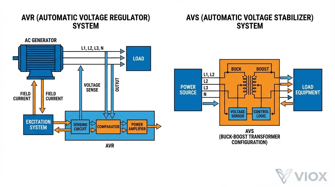
An Automatic Voltage Regulator (AVR) is an electronic device designed to automatically maintain a constant voltage level in electrical systems, particularly in generator applications. AVRs work by continuously monitoring the generator’s output voltage and adjusting the field excitation current to compensate for load variations, ensuring stable power delivery regardless of demand fluctuations.
Core Functions of AVR Systems
Modern AVRs perform several critical functions beyond basic voltage regulation:
- Voltage Stabilization: Maintains output voltage within ±1% accuracy despite load changes
- Reactive Load Division: Distributes reactive power between parallel-connected generators
- Overvoltage Protection: Prevents voltage spikes during sudden load disconnection
- Power Factor Control: Ensures generators operate at optimal power factor when grid-connected
- Surge Protection: Guards against electrical surges and generator overload conditions
What is an Automatic Voltage Stabilizer (AVS)?
An Automatic Voltage Stabilizer (AVS) is an electrical device installed on the load side to protect equipment from voltage fluctuations in the mains power supply. Unlike AVRs that regulate generator output, AVS units sit between the utility grid and sensitive loads, automatically adjusting incoming voltage to deliver a stable output within safe operating ranges.
How AVS Technology Works
AVS devices employ buck-boost transformer technology to correct voltage deviations:
- Boost Operation: When input voltage drops below required levels (brownout/sag), the stabilizer adds voltage to meet target output
- Buck Operation: When voltage rises above safe levels (surge), it reduces voltage to prevent equipment damage
- Bypass Mode: During normal voltage conditions, some AVS units allow direct power flow without regulation to maximize efficiency
AVR vs AVS: Comprehensive Comparison Table
| Aspect | AVR (Automatic Voltage Regulator) | AVS (Automatic Voltage Stabilizer) |
|---|---|---|
| Primary Application | Generator systems (supply side) | Load protection (demand side) |
| Installation Location | Integrated within generator control system | Between mains supply and equipment |
| Control Method | Adjusts generator field excitation current | Buck-boost transformer tap switching |
| Voltage Range | Maintains generator output at rated voltage | Handles ±25% to ±50% input fluctuations |
| Response Time | Varies by type (50ms-5 seconds) | 20-30ms (static) to 50ms-5s (servo) |
| Load Handling | Controls generator reactive power | Protects downstream equipment |
| Parallel Operation | Coordinates multiple generators | Independent load protection |
| Typical Capacity | Matches generator rating (kVA) | Sized to connected load requirements |
| Maintenance Needs | Moderate (servo types require more) | Low (static) to moderate (servo) |
| Cost Range | Integrated into generator cost | Separate purchase based on capacity |
Types of Voltage Regulation Technologies
Servo-Controlled Stabilizers
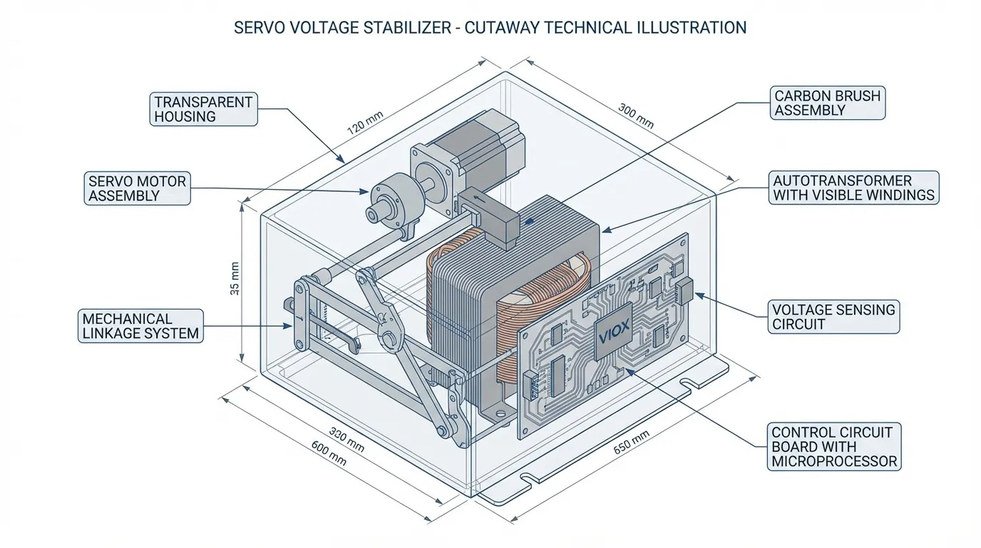
Servo voltage stabilizers use an electromechanical servo motor to drive a variable autotransformer, providing precise voltage correction through physical movement of a carbon brush along transformer windings. This proven technology handles high inrush currents excellently and suits approximately 95% of industrial applications, though response times are slower (50ms-5 seconds) due to mechanical components.
Advantages:
- Excellent for inductive loads (motors, transformers)
- Handles voltage fluctuations up to ±50%
- High accuracy (±1% regulation)
- Proven reliability in harsh environments
Limitations:
- Slower response time due to mechanical movement
- Regular maintenance required for servo motor and brushes
- Audible noise during operation
Static Voltage Stabilizers
Static stabilizers employ solid-state electronic components (IGBTs, SCRs) without moving parts, enabling near-instantaneous voltage correction within 20-30 milliseconds. This technology offers superior response speed and minimal maintenance requirements, making it ideal for sensitive electronic equipment and applications requiring rapid voltage adjustment.
Advantages:
- Ultra-fast response (20-30ms)
- No moving parts—minimal maintenance
- Silent operation
- Compact design
Limitations:
- Higher initial cost
- May struggle with extreme inrush currents
- Typically handles ±25% voltage variation
Application Comparison: When to Use AVR vs AVS
AVR Applications (Generator Systems)
| Application | Why AVR is Essential |
|---|---|
| Standby Generators | Maintains stable voltage during utility outages regardless of building load changes |
| Industrial Power Generation | Coordinates parallel generators and manages reactive power distribution |
| Marine Electrical Systems | Regulates shipboard generator output despite varying propulsion and auxiliary loads |
| Data Center Backup Power | Ensures UPS systems receive consistent voltage during generator operation |
| Construction Sites | Stabilizes portable generator output for sensitive power tools and equipment |
AVS Applications (Load Protection)
| Application | Why AVS is Essential |
|---|---|
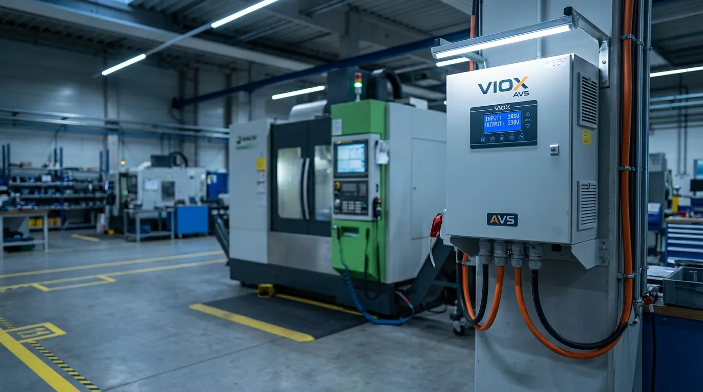
| CNC Machine Tools | Protects precision equipment from grid voltage fluctuations that affect machining accuracy |
| Medical Equipment | Ensures diagnostic and life-support systems receive stable power supply |
| IT Infrastructure | Guards servers and networking equipment against brownouts and voltage sags |
| HVAC Systems | Prevents compressor damage from low-voltage conditions during peak demand |
| Automated Production Lines | Maintains consistent voltage to PLCs and control systems preventing production errors |
For comprehensive guidance on protecting industrial control systems, see our article on industrial control panel components.
Technical Specifications Comparison
Voltage Regulation Performance
| Parameter | Servo AVR/AVS | Static AVR/AVS |
|---|---|---|
| Input Voltage Range | 150-270V (±50%) | 170-270V (±25%) |
| Output Voltage Accuracy | ±1% | ±1% |
| Correction Speed | 100V/second | Instantaneous (20-30ms) |
| Response Time | 50ms – 5 seconds | 20-30 milliseconds |
| Efficiency | 95-98% | 96-99% |
| Waveform Distortion | <3% THD | <2% THD |
| Overload Capacity | 150% for 60 seconds | 120% for 30 seconds |
| Operating Temperature | -10°C to 50°C | -10°C to 40°C |
Maintenance Requirements
Servo-Based Systems:
- Carbon brush inspection: Every 6 months
- Servo motor lubrication: Annually
- Transformer winding check: Every 2 years
- Contact cleaning: Every 12 months
Static Systems:
- IGBT/SCR thermal inspection: Annually
- Capacitor testing: Every 2 years
- Cooling fan replacement: Every 3-5 years
- Firmware updates: As available
Understanding proper circuit protection selection ensures your voltage regulation system integrates properly with overall electrical safety.
Selection Criteria: Choosing Between AVR and AVS Technologies
Load Type Considerations
Choose Servo Technology When:
- Operating inductive loads (motors, transformers, welding equipment)
- Handling high inrush currents during equipment startup
- Budget constraints favor lower initial investment
- Proven reliability in harsh environments is priority
- Voltage fluctuations exceed ±25% regularly
Choose Static Technology When:
- Protecting sensitive electronic equipment (computers, PLCs, medical devices)
- Millisecond-level response time is critical
- Maintenance access is limited or costly
- Silent operation is required (office, hospital environments)
- Space constraints demand compact solutions
For motor protection applications, review our guide on thermal overload relay vs MPCB differences.
Environmental Factors
| Environment | Recommended Technology | Reasoning |
|---|---|---|
| Dusty/Dirty Industrial | Servo (enclosed type) | Fewer sensitive electronics exposed |
| Clean Room/Laboratory | Static | No mechanical wear particles generated |
| High Vibration Areas | Static | No moving parts to misalign |
| Extreme Temperatures | Servo | Better thermal tolerance range |
| Marine/Coastal | Static (IP65+ rated) | Corrosion-resistant solid-state design |
Common Misconceptions About AVR and AVS
Myth 1: “AVR and AVS Are Completely Different Devices”
Reality: The terms are often used interchangeably in the industry. Both devices perform voltage regulation, with the primary distinction being application context—AVR for generator control, AVS for load protection. Many manufacturers use both terms to describe the same product line.
Myth 2: “Static Stabilizers Are Always Better Than Servo”
Reality: While static stabilizers offer faster response times, servo stabilizers excel at handling high inrush currents and extreme voltage fluctuations. For motor-driven loads and heavy industrial applications, servo technology remains the superior choice in 95% of cases.
Myth 3: “Voltage Stabilizers Eliminate the Need for Surge Protection”
Reality: While AVS devices provide some protection against voltage variations, they don’t replace dedicated surge protection devices (SPDs). A comprehensive protection strategy requires both voltage stabilization and surge suppression, especially in areas with frequent lightning activity.
Myth 4: “Larger Capacity Is Always Better”
Reality: Oversizing voltage regulators wastes money and reduces efficiency. Proper sizing requires calculating actual load requirements plus a 20-30% safety margin. Undersizing causes overload trips, while oversizing increases no-load losses and initial costs.
For proper electrical load calculation methods, consult our guide on determining your home’s electrical load.
Integration with Electrical Protection Systems
Coordinating AVR/AVS with Circuit Protection
Voltage regulation devices must integrate properly with upstream and downstream protection:
- Upstream Protection: Install appropriately rated MCCBs or MCBs to protect the stabilizer itself
- Downstream Protection: Size circuit breakers based on stabilized output voltage and connected load
- Ground Fault Protection: Integrate RCCBs for personnel safety
- Coordination Study: Ensure proper selectivity between protection devices
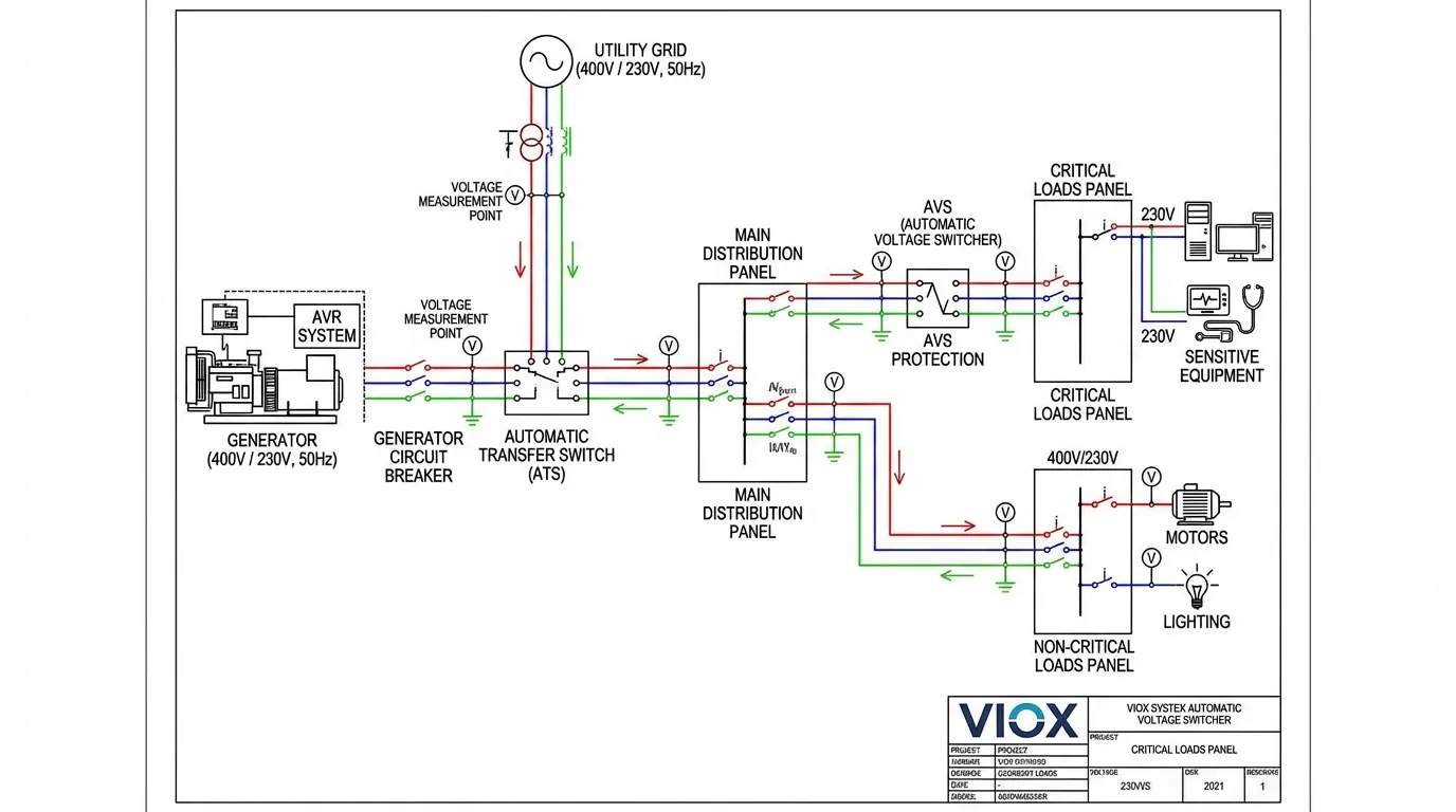
Automatic Transfer Switch (ATS) Integration
When combining generator AVR systems with utility AVS protection, proper ATS configuration ensures seamless transitions:
- Generator Mode: AVR maintains stable voltage during utility outages
- Utility Mode: AVS protects loads from grid fluctuations
- Transfer Timing: Coordinate ATS switching with stabilizer response times
- Neutral Management: Ensure proper neutral bonding in both operating modes
Installation Best Practices
Sizing Guidelines
Step 1: Calculate Total Connected Load
Total Load (VA) = Sum of all equipment ratings × Diversity Factor
Diversity Factor = 0.7-0.9 (depending on simultaneous operation)
Step 2: Account for Power Factor
Apparent Power (VA) = Real Power (W) ÷ Power Factor
For inductive loads, use PF = 0.8
For resistive loads, use PF = 1.0
Step 3: Add Safety Margin
Required Stabilizer Rating = Total Load × 1.25 (25% margin)
For high inrush loads (motors), use 1.5× multiplier
Installation Location Requirements
| Requirement | Specification | Reason |
|---|---|---|
| Ambient Temperature | 0°C to 40°C | Ensures optimal component operation |
| Ventilation Clearance | 300mm all sides | Prevents thermal overload |
| Humidity | <90% non-condensing | Protects electrical components |
| Mounting Height | 1.5-2.0m from floor | Facilitates maintenance access |
| Cable Entry | Bottom or side (IP rating dependent) | Prevents water ingress |
For proper enclosure selection, review our guide on electrical enclosure material selection.
Troubleshooting Common Issues
AVR/AVS Not Regulating Properly
Symptoms: Output voltage fluctuates beyond acceptable range
Possible Causes:
- Sensing circuit malfunction—verify input voltage connections
- Worn carbon brushes (servo types)—inspect and replace if <5mm remaining
- Failed IGBT/SCR (static types)—test with thermal imaging
- Incorrect voltage setting—recalibrate reference voltage
- Overload condition—verify actual load vs rated capacity
Slow Response Time
Symptoms: Equipment experiences voltage dips before stabilizer corrects
Possible Causes:
- Servo motor mechanical binding—lubricate and check for obstructions
- Control circuit delay settings—adjust response parameters
- Undersized unit for load inrush—upgrade to higher capacity
- Weak input voltage—verify utility supply meets minimum requirements
Frequent Overload Tripping
Symptoms: Stabilizer shuts down during normal operation
Possible Causes:
- Undersized for actual load—recalculate load requirements
- High inrush current from motor starts—add soft starters or upgrade capacity
- Thermal overload from poor ventilation—improve cooling airflow
- Faulty overload relay—test and replace if necessary
For comprehensive circuit breaker troubleshooting, see our article on why circuit breakers trip.
Cost-Benefit Analysis
Initial Investment Comparison
| Technology | Cost per kVA | Installation Cost | Total 10kVA System |
|---|---|---|---|
| Servo AVR/AVS | $80-150 | $200-400 | $1,000-1,900 |
| Static AVR/AVS | $150-250 | $150-300 | $1,650-2,800 |
| Digital AVR/AVS | $200-350 | $150-300 | $2,150-3,800 |
Lifetime Operating Costs (10-Year Period)
| Cost Factor | Servo | Static |
|---|---|---|
| Maintenance | $800-1,200 | $200-400 |
| Energy Loss (2% efficiency difference) | $1,500 | $1,000 |
| Component Replacement | $600-900 | $300-500 |
| Downtime Costs | $500-1,000 | $200-400 |
| Total 10-Year Operating Cost | $3,400-4,600 | $1,700-2,300 |
ROI Calculation
Equipment Protection Value:
- Average cost of voltage-related equipment failure: $5,000-50,000
- Probability of failure without protection: 15-25% over 10 years
- Expected savings: $750-12,500 per protected equipment
Payback Period:
- Typical payback: 6-18 months for critical equipment
- ROI: 200-500% over 10-year lifespan
Future Trends in Voltage Regulation Technology
Smart AVR/AVS Systems
Modern voltage regulators increasingly incorporate IoT connectivity and advanced monitoring:
- Remote Monitoring: Real-time voltage, current, and temperature data accessible via cloud platforms
- Predictive Maintenance: AI algorithms analyze performance trends to predict component failures
- Automatic Reporting: Email/SMS alerts for voltage events and maintenance requirements
- Energy Analytics: Track power quality metrics and identify efficiency improvement opportunities
Integration with Renewable Energy
As solar and battery storage systems proliferate, voltage regulation evolves:
- Bidirectional Regulation: Handle both grid-to-load and solar-to-grid power flows
- MPPT Coordination: Work with solar inverter maximum power point tracking
- Battery Management: Integrate with BESS systems for seamless voltage control
- Microgrid Support: Enable stable operation in islanded mode
For solar-specific voltage considerations, review our guide on solar combiner box voltage ratings.
Frequently Asked Questions (FAQ)
Q: Can I use the same device as both AVR and AVS?
A: Technically yes—the core technology is similar. However, AVRs designed for generators include specific features for field excitation control and parallel operation that load-side AVS units don’t require. Always select devices designed for your specific application.
Q: How do I know if I need an AVR or AVS?
A: If you’re regulating generator output voltage, you need an AVR (usually integrated into the generator). If you’re protecting equipment from utility grid fluctuations, you need an AVS installed between the supply and your loads.
Q: What’s the difference between AVR and UPS?
A: AVR/AVS regulate voltage but don’t provide backup power during outages. A UPS includes battery backup for continuous operation during power failures, plus voltage regulation. For critical loads, use both: AVS for continuous voltage conditioning and UPS for backup power.
Q: Do voltage stabilizers increase electricity bills?
A: Quality stabilizers operate at 95-98% efficiency, resulting in minimal energy loss (2-5%). The cost of this loss is far outweighed by prevented equipment damage and extended appliance lifespan.
Q: Can I install an AVS myself?
A: While technically possible for small plug-in units, proper installation of industrial AVS systems requires qualified electricians to ensure correct sizing, wiring, grounding, and protection coordination. Improper installation voids warranties and creates safety hazards.
Q: How long do AVR/AVS devices last?
A: Servo types typically last 10-15 years with proper maintenance. Static types can exceed 15-20 years due to fewer wear components. Lifespan depends heavily on operating conditions, load characteristics, and maintenance quality.
Conclusion: Making the Right Choice for Your Application
Understanding the difference between AVR and AVS comes down to recognizing their application contexts: AVRs regulate generator output on the supply side, while AVS devices protect loads on the demand side. Both employ similar voltage regulation principles but serve distinct roles in comprehensive electrical protection strategies.
When selecting voltage regulation technology, prioritize these factors:
- Application Type: Generator control (AVR) vs. load protection (AVS)
- Load Characteristics: Inductive loads favor servo; sensitive electronics favor static
- Response Requirements: Critical applications need static; general use accepts servo
- Maintenance Capability: Limited access suggests static; routine maintenance allows servo
- Budget Constraints: Balance initial cost against lifetime operating expenses
At VIOX Electric, we manufacture both servo and static voltage regulation solutions engineered to IEC and UL standards, providing reliable protection for industrial, commercial, and residential applications worldwide. Our technical team can help you select the optimal voltage regulation strategy for your specific requirements.
For expert guidance on voltage regulation system design and selection, contact VIOX Electric’s engineering support team or explore our comprehensive range of electrical protection components.
