On this page
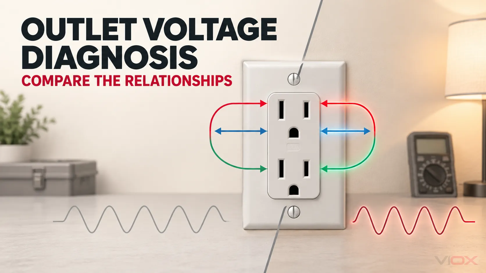
Diagnose a 120 V outlet by comparing relationships, not by judging one voltage in isolation. At a normally operating grounding receptacle, hot-to-neutral and hot-to-ground should be similar, while neutral-to-ground should be much smaller and may increase with load. If hot-to-neutral falls while neutral-to-ground rises, suspect voltage drop in the neutral path. If hot-to-neutral and hot-to-ground fall together, investigate the line path or the upstream supply. Normal-looking voltages do not prove that the equipment grounding path has acceptably low impedance.
Energized testing boundary: This article explains diagnostic logic for qualified electrical workers. It does not instruct unqualified readers to insert probes into an energized receptacle. OSHA states that only qualified persons may perform testing on electric circuits or equipment, and that instruments, leads, probes, and accessories must be inspected and rated for the circuit and environment. Never use resistance or continuity mode on an energized circuit.
Scope: Which Outlet and Wiring System?
This guide applies to a conventional North American 120 V, 15 A or 20 A grounding-type receptacle supplied by:
- an ungrounded conductor, commonly called hot;
- a grounded circuit conductor, commonly called neutral; and
- an equipment grounding conductor, commonly called ground.
It does not provide a diagnostic table for 230 V IEC socket systems, isolated-ground healthcare circuits, ungrounded systems, separately derived systems with unusual bonding arrangements, or exact GFCI/AFCI test procedures. Those systems can produce different relationships and require their own documentation and rules.
For conductor terminology before troubleshooting, see Line vs Load vs Neutral Wire.
The Three Voltage Relationships
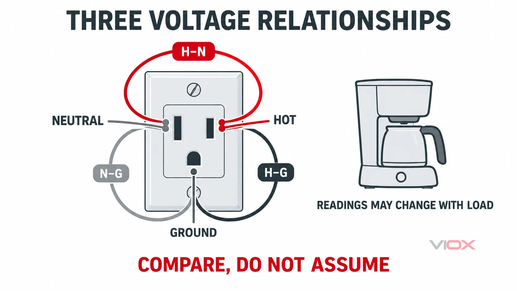
A qualified person normally begins by identifying three voltage relationships at the receptacle.
| Measurement | What it represents | What it can help reveal | What it does not prove |
|---|---|---|---|
| Hot to neutral (H-N) | Voltage available to a normal 120 V load | Missing supply, line or neutral voltage drop, abnormal supply voltage | Correct polarity, grounding-path integrity, or source impedance by itself |
| Hot to ground (H-G) | Voltage between the ungrounded conductor and equipment grounding path | Comparison reference for H-N; possible open-ground indication | A low-impedance grounding path merely because a digital meter displays voltage |
| Neutral to ground (N-G) | Voltage difference created by neutral-path drop and other system conditions | Neutral-path loading or resistance when interpreted with H-N and H-G | A universal pass/fail result, absence of objectionable current, or correct downstream bonding |
In a simple loaded branch circuit, the hot and neutral conductors both have impedance. Current through those conductors produces voltage drop. The equipment grounding conductor should not carry normal load current, so its voltage profile is different. That is why comparing H-N, H-G, and N-G under a controlled load can indicate which side of the circuit is losing voltage.
Do not turn the relationship into a rigid equation. Meter accuracy, conductor impedance, load waveform, bonding location, parallel paths, measurement point, and supply variation all affect the result.
Fast Diagnostic Matrix
Use this table as a fault-class screen, not as permission to continue energized work when the condition is unstable, damaged, or unclear.
| Observed pattern | Likely fault class | Why the pattern occurs | Next safe action |
|---|---|---|---|
| H-N and H-G are similar; N-G is much smaller | Relationship is broadly consistent with a normal energized circuit | Neutral is carrying load current; ground is serving as the comparison reference | Continue only if the complaint remains and the test plan calls for a controlled load or recording |
| H-N is normal but the designated hot slot-to-ground reading is near zero, while the other slot-to-ground is near nominal | Hot and neutral may be reversed at the receptacle | The polarized slot identities no longer match conductor function | De-energize, lock out as applicable, verify absence of voltage, then inspect conductor termination and upstream polarity |
| H-N is present but H-G is absent, unstable, or clearly inconsistent | Open or ineffective equipment grounding path is possible | The load circuit can operate through hot and neutral even when the grounding path is missing | Stop treating the receptacle as grounded; de-energize and verify the grounding path with an appropriate method |
| H-G remains near nominal but H-N is absent, unstable, or collapses under load | Open or high-resistance neutral is possible | The hot conductor and grounding reference remain available while the normal return path is interrupted | Stop using the circuit; isolate it and inspect the neutral path, including shared-neutral conditions |
| No-load voltage looks normal; H-N falls under load and N-G rises | High resistance or excessive drop in the neutral path is possible | Load current produces increased voltage drop between the receptacle neutral and the bonding point | De-energize and inspect neutral terminations and the circuit path; evaluate loading and conductor condition |
| No-load voltage looks normal; H-N and H-G both fall similarly under load | High resistance in the hot path or upstream voltage sag is possible | Both measurements share the same ungrounded conductor and source | Compare another circuit or upstream point using an approved test plan; inspect line-side connections after isolation |
| Voltage is intermittent, jumps with other loads, or varies over time | Loose connection, shared-neutral problem, utility variation, switching disturbance, or load interaction is possible | A spot reading cannot capture event timing or correlation | Stop if overvoltage, heating, arcing, or instability is suspected; use qualified inspection and recording equipment |
| Three-light tester reports “correct,” but the complaint remains | Tester limitation, high resistance, bootleg ground, or intermittent fault remains possible | Simple testers identify only a limited set of wiring states | Escalate to instrumented tests; do not treat the light pattern as proof of full circuit integrity |
No single row proves the exact physical defect. It identifies the next branch of the investigation.
Why No-Load and Loaded Readings Must Be Compared
A high-resistance connection can pass enough current for a high-impedance digital multimeter to display a normal-looking voltage. The same connection may lose substantial voltage when a meaningful load is applied.
That difference is central to outlet troubleshooting:
- No-load measurement: shows that electrical potential is present, but may hide poor connection integrity.
- Controlled loaded measurement: shows how the circuit behaves when current flows.
- Comparison at another point: helps separate a local branch-circuit problem from an upstream supply problem.
- Measurement over time: exposes events that a spot check misses.
The controlled load must be appropriate for the circuit, receptacle, test equipment, and work procedure. This article does not prescribe a portable appliance or test current. Improvised high-power loads can overheat an already damaged connection and should not be used as a substitute for a purpose-designed test instrument and qualified judgment.
The calculation behind conductor drop is still ΔV = I × Z for the relevant AC path, but a receptacle test does not independently reveal every component of that impedance. For formula-based design work, use VIOX’s voltage-drop calculation guide.
High-Resistance Neutral vs High-Resistance Hot
Both faults can make equipment see low voltage, but their comparative readings differ.
High-resistance neutral path
When the neutral path has excessive resistance, load current raises the neutral potential at the receptacle relative to the equipment grounding reference. Under load, the expected pattern is:
- H-N decreases;
- N-G increases; and
- H-G may remain closer to the upstream source voltage than H-N.
Possible physical causes include a loose terminal, damaged conductor, poor splice, overheated connection, or an overloaded path. A multiwire branch circuit adds a more serious possibility: an open or unstable shared neutral can drive the two 120 V loads away from their expected voltages. If one receptacle becomes unusually high while another becomes low as loads change, stop testing and isolate the system for qualified inspection.
High-resistance hot path
When excessive resistance is on the ungrounded conductor, both H-N and H-G use that same impaired path. Under load, both readings tend to fall together. N-G may not rise enough to account for the full loss.
The pattern can also occur when the upstream supply itself sags. Compare measurements at an appropriate upstream or unaffected circuit only under a defined safe work plan. Do not open energized boxes merely to obtain another comparison point.
Polarity, Open Ground, and False Ground Indications
Reversed hot and neutral
A reversed-polarity receptacle can still power many loads, so “the appliance works” is not evidence of correct polarity. The U.S. Consumer Product Safety Commission has treated reverse-polarity outlet products as shock and fire hazards because polarization is part of how connected equipment controls which internal parts remain connected to the ungrounded conductor.
A three-light tester can screen for common polarity errors, while a qualified person can interpret slot-to-ground relationships. Correction requires de-energization and inspection, not merely rotating a plug or relabeling the receptacle.
Open equipment ground
A normal H-N reading does not require the equipment grounding conductor, so an ungrounded receptacle may continue to operate loads. H-G may be missing or unstable, but a sensitive meter can also display capacitively coupled or otherwise misleading voltage.
Grounding-path verification requires an appropriate continuity or impedance method performed under the correct energized or de-energized conditions. OSHA’s assured equipment grounding guidance separates continuity testing from terminal-connection verification; a voltage indication alone is not the complete test.
Bootleg or downstream neutral-ground connection
Connecting neutral to the ground terminal downstream of the permitted bonding point can make a basic tester display a reassuring pattern while placing normal return current on grounding paths or connected metalwork. Three receptacle voltages may not reveal this condition because neutral and ground have been forced close together locally.
Inspection, current measurement, impedance testing, and knowledge of the system bonding arrangement may be required. For the system boundary, see Neutral Bar vs Grounding Bar.
Do Not Use a Universal Neutral-to-Ground Limit
Neutral-to-ground voltage is created by current flowing through neutral-path impedance. It changes with:
- load current and load waveform;
- conductor length and size;
- connection resistance;
- the location of the neutral-ground bond;
- shared-neutral and parallel-path conditions;
- where the measurement is taken; and
- source and transformer configuration.
Values such as 1 V, 2 V, or 3 V are often repeated as rules of thumb, but they are not a universal diagnosis or code limit for every receptacle. Trend and context matter more: Does N-G rise sharply when a known load starts? Does H-N fall by a corresponding amount? Is the behavior local to one outlet, common to one branch circuit, or visible across the service?
Similarly, the ANSI C84.1 voltage-range framework distinguishes service voltage from utilization voltage. A nominal 120 V label does not mean every instantaneous reading must equal exactly 120.0 V. Apply the current edition, utility requirements, equipment input limits, and measurement conditions rather than copying one internet threshold.
Choose the Instrument by the Question
| Instrument | Best use | Important limitation |
|---|---|---|
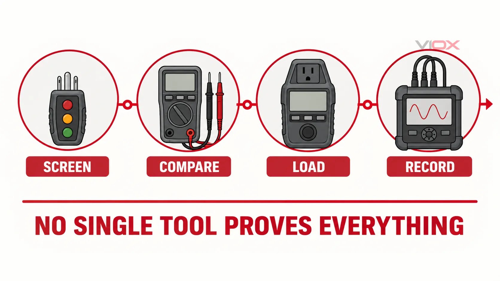
| Three-light outlet tester | Quick screen for a limited set of common polarity and conductor-presence conditions | UL category information explicitly describes outlet circuit testers as non-comprehensive diagnostic instruments; they cannot prove every hazardous wiring state |
| Digital multimeter | Compare H-N, H-G, and N-G voltage relationships | A high-impedance reading may look normal through a poor connection and does not prove grounding-path impedance |
| Purpose-designed receptacle/load tester | Observe voltage behavior under a controlled load and, depending on the instrument, estimate circuit performance | Results depend on the instrument method; it does not replace visual inspection or correction of damaged wiring |
| Clamp meter | Check conductor current and investigate neutral or grounding-path current where conductors can be safely accessed | Accessing the correct conductor may require panel or box work and does not identify the connection defect by itself |
| Power-quality recorder | Capture sags, swells, interruptions, and timing correlations over time | Requires correct setup, event thresholds, duration, and interpretation; a recorder cannot repair a wiring fault |
Before any measurement, the qualified person must select an instrument and accessories rated for the circuit and environment, inspect them for damage, and understand the manufacturer’s instructions. A non-contact voltage detector is useful as an initial indication, but it does not replace the required test method for proving a circuit de-energized.
When the Outlet Is Not the Root Cause
If outlet wiring and loaded voltage behavior appear normal, broaden the investigation without assuming the utility is responsible.
Several outlets on one branch show the same drop
The problem may be at a shared upstream splice, breaker termination, branch conductor, or neutral connection. Map which points are affected before disturbing wiring.
Several circuits change together
Look for a service, feeder, panel, transformer, or utility-side condition. In split-phase systems, opposite changes on the two 120 V legs can be a warning sign of an unstable shared or service neutral.
RMS voltage is normal but electronic equipment still resets
A spot RMS reading may miss short interruptions, repetitive sags, waveform distortion, or transients. Use a recorder or power-quality analyzer with a measurement plan tied to the equipment symptom and event time.
GFCI or breaker trips instead of voltage dropping
The primary task has changed from voltage diagnosis to protection diagnosis. A leakage path, shared or borrowed neutral, connected load fault, or device issue may be involved. See How Shared and Borrowed Neutrals Cause RCD and RCBO Tripping and RCD vs GFCI vs Surge Protector for those boundaries.
Stop Conditions
Stop the test and arrange isolation and qualified inspection when any of the following is present:
- visible heat damage, discoloration, melted plastic, or a loose receptacle body;
- crackling, arcing, smoke, odor, or abnormal heat;
- unstable or unexpectedly high voltage;
- evidence of an open or unstable shared neutral;
- damaged meter, leads, probes, receptacle, or enclosure;
- water, contamination, or an environment outside the instrument rating;
- a test result that conflicts with the known system arrangement; or
- any need to expose energized parts beyond the worker’s training, PPE, procedure, or authorization.
The correct troubleshooting sequence is define the system → screen the wiring state → compare voltage relationships → compare no-load and loaded behavior → localize the affected area → de-energize and inspect → verify the repair. Replacing the receptacle before identifying the fault can leave an upstream high-resistance connection or neutral problem untouched.
Sources and Technical References
- OSHA Electrical Hazards in Construction Student Workbook
- OSHA Field Service Memo on Electrical Testing Equipment
- OSHA Assured Equipment Grounding Conductor Program
- UL Guide Information for Outlet Circuit Testers and UL 1436
- NEMA public scope for ANSI C84.1-2020, Electric Power Systems and Equipment—Voltage Ratings
- U.S. CPSC reverse-polarity outlet converter recall
Written by: VIOX Editorial Team
Last updated: September 18, 2026