On this page
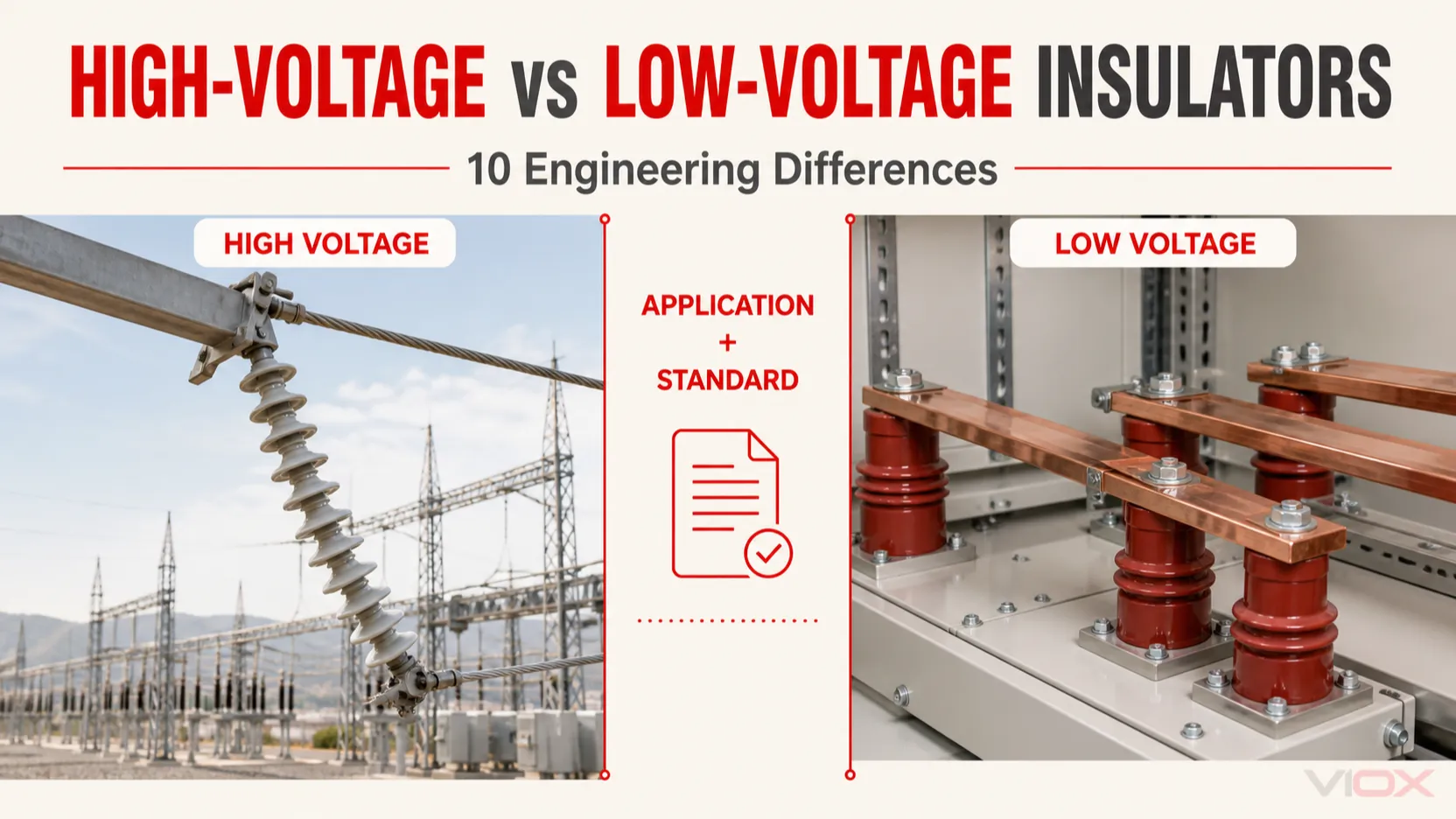
High-voltage and low-voltage insulators perform the same basic job—electrically separating and mechanically supporting conductive parts—but they are engineered for different system voltages, insulation levels, environments, geometries, loads, and verification requirements. In the IEC low-voltage equipment context, low voltage extends through 1,000 V AC or 1,500 V DC. Above that boundary, the applicable product and system standard—not an HV or LV label by itself—determines the required insulator design.
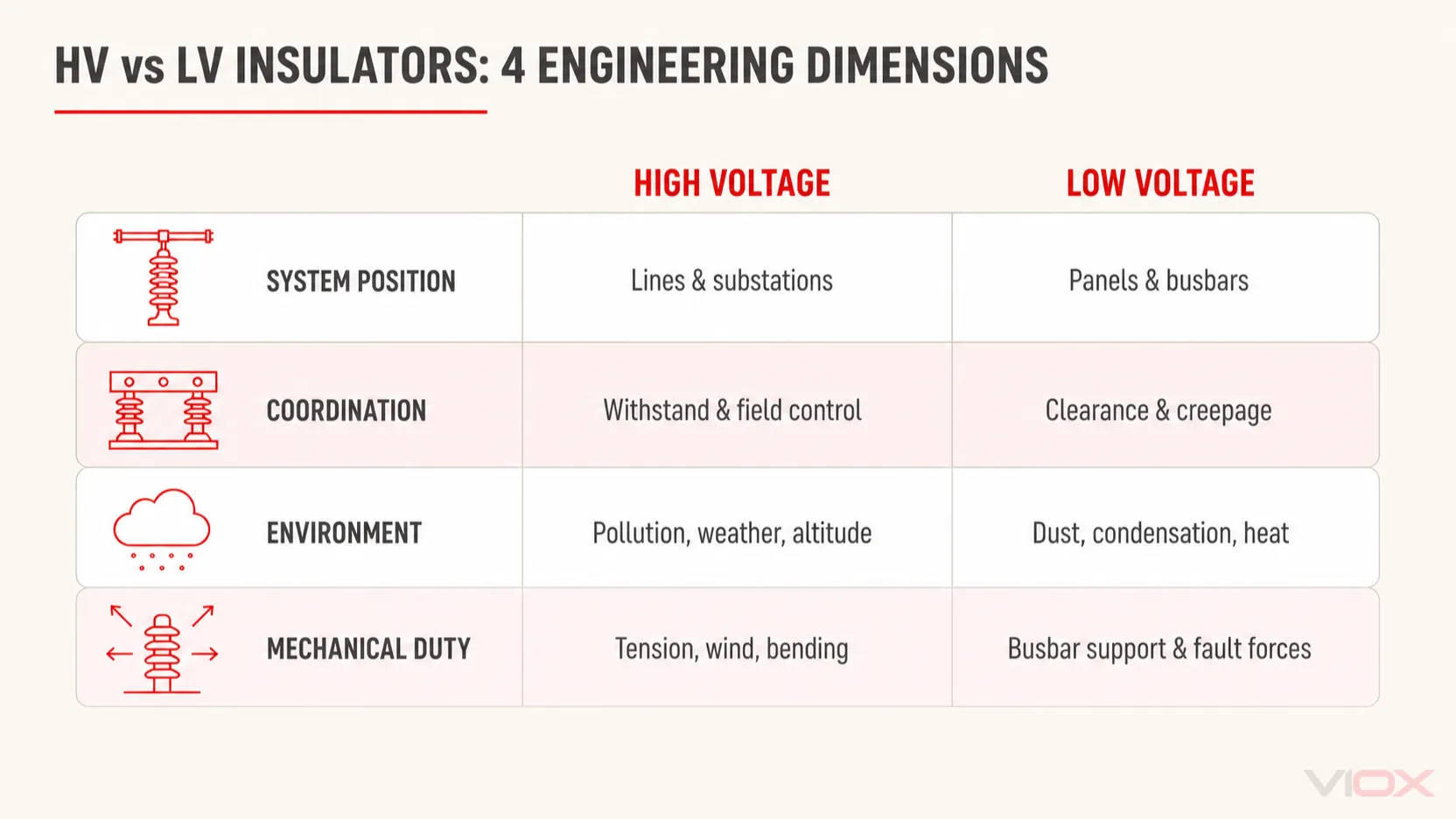
The practical difference is therefore not simply “large versus small” or “porcelain versus plastic.” A high-voltage overhead-line insulator and a low-voltage busbar support occupy different system positions and are verified against different electrical, mechanical, and environmental duties.
High-Voltage vs Low-Voltage Insulators at a Glance
| Comparison basis | High-voltage insulators | Low-voltage insulators |
|---|---|---|
| 1. Voltage and standard scope | Used in systems above the relevant low-voltage boundary; the exact scope depends on the equipment and product standard | Used within low-voltage equipment and supply-system limits, commonly up to 1,000 V AC or 1,500 V DC in the IEC context |
| 2. Typical system position | Overhead lines, substations, outdoor buswork, and external insulation on high-voltage equipment | Switchgear, panelboards, control cabinets, busbar systems, and equipment assemblies |
| 3. Insulation coordination | Must address system highest voltage, power-frequency and impulse withstand, switching or lightning stresses where applicable | Must address rated voltage, transient overvoltage, overvoltage category, pollution degree, and the relevant equipment insulation requirements |
| 4. Clearance and creepage | Longer and application-specific air clearances and surface paths; external insulation may be dimensioned for site pollution | More compact spacing is possible, but clearance and creepage still depend on voltage, pollution degree, material group, altitude, and product rules |
| 5. Electric-field and profile design | May use sheds, strings, optimized profiles, corona or grading hardware, and controlled field distribution where required | Commonly uses compact molded shapes designed around conductor spacing, mounting, tracking resistance, and enclosure constraints |
| 6. Materials | Porcelain, toughened glass, silicone-rubber composites, epoxy and other verified insulation systems, depending on the application | Molded thermosets, epoxy systems, engineering polymers, porcelain and other verified materials, depending on the component |
| 7. Mechanical duty | Can include conductor tension, cantilever or bending load, wind, ice, vibration, and equipment-terminal loads | Can include busbar weight, assembly vibration, mounting torque and electrodynamic forces during short-circuit conditions |
| 8. Environmental exposure | Frequently outdoor and directly exposed to pollution, moisture, ultraviolet radiation, altitude and weather—but not universally | Frequently inside equipment, but may still face condensation, conductive dust, heat, chemicals or outdoor-enclosure conditions |
| 9. Testing and evidence | Product-specific electrical and mechanical type, sample and routine tests under the relevant HV insulator standard | Component, material and assembly evidence under the applicable low-voltage product or assembly framework |
| 10. Inspection and maintenance | Driven by construction, criticality, contamination, condition data and the asset owner’s program | Driven by the assembly environment, thermal/mechanical condition, contamination and manufacturer guidance |
Neither column is universally “better.” The correct design is the one whose verified ratings, geometry, interfaces and test evidence match the actual system.
1. Voltage Class Is a Standards Boundary, Not a Product Shortcut
IEC 60664-1:2020+AMD1:2025 addresses insulation coordination for equipment connected to low-voltage supply systems with rated voltage up to 1,000 V AC or 1,500 V DC. It provides a framework for determining clearances, creepage distances and solid-insulation criteria within that scope.
For equipment above this boundary, the word high voltage can be used broadly in IEC standards, even where industry practice calls part of the range medium voltage. An 11 kV distribution system, for example, is commonly called medium voltage, while an overhead-line insulator standard may still define its scope as above 1,000 V.
The VIOX guide to low-, medium- and high-voltage classification explains this terminology in more detail. For specifications, state the actual system voltage, AC or DC duty and governing standard instead of writing only “LV insulator” or “HV insulator.”
2. Their System Positions Are Usually Different
High-voltage insulators commonly form part of a power-network insulation system. Examples include suspension and tension strings on overhead lines, line-post insulators, substation post insulators and external insulation associated with high-voltage apparatus. They must separate energized conductors from grounded structures while supporting the mechanical loads created by the application.
Low-voltage insulators are often located inside an assembly. Typical examples include:
- busbar support insulators in switchboards and distribution equipment;
- standoff insulators that maintain spacing above a grounded mounting surface;
- barriers, supports and insulated mounting structures inside control panels; and
- molded insulating parts incorporated into switching and connection equipment.
A busbar insulator supports a current-carrying busbar but normally does not carry the load current itself. A standoff performs a related support function, although the terminology and geometry may differ; see standoff insulators vs busbar insulators for that narrower distinction.
This system-position difference explains why a compact LV busbar support cannot be evaluated as if it were a shortened overhead-line insulator.
3. Insulation Coordination Uses Different Inputs
Both voltage groups require insulation coordination, but the dominant inputs and governing documents differ.
For a high-voltage system, the specification may need to coordinate:
- highest voltage for equipment;
- power-frequency withstand level;
- lightning-impulse and, where applicable, switching-impulse withstand;
- phase-to-ground and phase-to-phase insulation distances;
- external insulation performance under pollution and altitude; and
- the insulation level of connected equipment.
For low-voltage equipment, the design commonly considers:
- rated insulation and working voltage;
- transient overvoltage and overvoltage category;
- pollution degree in the local micro-environment;
- material group and comparative tracking behavior where applicable;
- altitude corrections; and
- the requirements of the complete product or assembly standard.
The decision is not made by comparing raw material dielectric-strength values. Insulator performance depends on the complete construction, thickness, geometry, surface condition, interfaces, manufacturing control and specified test method.
4. Clearance, Creepage and Pollution Have Different Design Weight
Clearance is the shortest distance through air between conductive parts. Creepage distance is the shortest path along the surface of solid insulation between those parts. Increasing system voltage and environmental severity can increase the required distances, but voltage is not the only variable.
Outdoor high-voltage insulation is especially sensitive to site pollution. Moisture combined with salt, industrial contamination, dust or other deposits can create a conductive surface path and increase leakage current or flashover risk. IEC TS 60815-1:2025 describes a structured process for assessing site pollution severity and developing candidate external-insulation dimensions. It does not prescribe one universal creepage value for every location and material.
Low-voltage insulators can be more compact, but their surface paths still matter. Conductive dust, condensation, chemical exposure and contamination inside an enclosure can change the effective micro-environment. A low-voltage label does not make creepage, clearance or tracking resistance optional.
5. High Voltage Places More Emphasis on Field and Profile Control
At higher voltages, local electric-field concentration becomes increasingly important. The insulator profile, metal fittings, conductor hardware and surrounding geometry can affect surface stress, corona activity and flashover performance.
Depending on the application, a high-voltage design may use:
- multiple insulator units in a string;
- sheds or skirts that lengthen the surface path;
- profiles selected for particular pollution behavior;
- grading or corona rings; or
- composite housings designed to manage environmental exposure.
These are possible engineering responses, not features found on every high-voltage insulator.
Low-voltage supports usually have a more compact molded profile. Their geometry is often driven by busbar spacing, mounting inserts, enclosure clearances, tracking resistance, heat exposure and assembly forces. Shorter size does not mean the shape is arbitrary.
6. Material Alone Does Not Determine Voltage Class
Porcelain is not automatically high voltage, and polymer is not automatically low voltage. Several material families appear on both sides of the comparison.
| Material family | High-voltage context | Low-voltage context | Verification concern |
|---|---|---|---|
| Porcelain or ceramic | Overhead-line and station insulation, apparatus insulation | Supports, terminals and specialized equipment parts | Glaze and body quality, mechanical integrity, interfaces and specified electrical tests |
| Toughened glass | Common in some overhead-line insulator units | Less common in compact panel supports | Unit design, mechanical characteristics and applicable line-insulator standard |
| Silicone-rubber composite | Composite line, station and apparatus insulation | Molded or overmolded insulating functions in some equipment | Core-housing interface, tracking/erosion behavior, environmental aging and product evidence |
| Epoxy or molded thermoset | Indoor post, apparatus and specialized insulation applications | Busbar and standoff supports in panels and assemblies | Formulation, molding quality, insert bonding, tracking resistance and mechanical duty |
| Engineering thermoplastic | Application-specific components | Compact barriers, supports and insulating parts | Temperature, flammability, tracking, mechanical and product-standard requirements |
The correct question is not “Which material is strongest?” It is “Has this complete insulator design been verified for the electrical, mechanical and environmental duty?”
7. Mechanical Loads Differ, but Both Can Be Severe
High-voltage overhead-line insulators may carry sustained conductor tension and loads from wind, ice, vibration or line geometry. Station-post and apparatus insulators may instead be dominated by cantilever, bending, compression or terminal loads. The mechanical requirement depends on the insulator type and installation.
Low-voltage busbar supports may appear smaller, yet they can experience substantial electrodynamic forces during a short circuit. The support spacing, busbar geometry, mounting method and complete assembly design determine the force transferred into each insulator. A low-voltage component should therefore not be described as “light duty” without evaluating its actual mechanical requirement.
This is another reason a voltage label cannot replace a datasheet or assembly calculation.
8. Environment Changes the Design on Both Sides
Many high-voltage line and substation insulators operate outdoors, so ultraviolet exposure, rain, humidity, pollution, altitude and weather are prominent design inputs. Nevertheless, not every HV insulator is outdoors; indoor switchgear and apparatus use high-voltage insulation too.
Many low-voltage busbar supports operate inside enclosures, but “inside” does not guarantee a clean, dry environment. Condensation, conductive dust, heat cycling, vibration and chemical contamination can all matter. Outdoor LV cabinets, transport equipment and industrial process environments may be particularly demanding.
The VIOX comparison of indoor vs outdoor busbar insulators covers that environmental decision in greater depth.
9. The Standards and Test Evidence Are Not Interchangeable
Different standards govern different insulator constructions and applications. A useful scope map is:
| Document | Relevant scope | What it does not prove by itself |
|---|---|---|
| IEC 60664-1:2020+AMD1:2025 | Insulation coordination for equipment connected to LV supply systems up to 1,000 V AC or 1,500 V DC | Certification or suitability of a particular busbar support or complete assembly |
| IEC 60383-1:2023 | Ceramic or glass insulator units for AC overhead lines above 1,000 V, with defined related applications and exclusions | Suitability of every post, apparatus, polymer or low-voltage insulator |
| IEC 61109:2025 | Composite suspension and tension insulators for overhead lines above 1,000 V AC and 1,500 V DC | Suitability of unrelated composite components or every high-voltage insulator type |
| IEC TS 60815-1:2025 | Selection and dimensioning principles for high-voltage external insulation in polluted conditions | One universal creepage distance or certification of a specific product |
A statement that a material “meets IEC” is incomplete. Procurement evidence should identify the exact standard, edition, product scope, declared ratings, test documentation and the specific model covered.
10. Inspection and Maintenance Must Be Condition-Based
It is misleading to say that all high-voltage insulators require frequent cleaning while all low-voltage insulators need almost no maintenance. The appropriate program depends on the technology, environment, system criticality, observed condition and asset-owner requirements.
High-voltage inspections may consider contamination, damaged sheds or units, corrosion, hardware condition, discharge evidence and changes identified by an approved monitoring program. Low-voltage assembly inspections may consider contamination, cracking, tracking, loose or damaged inserts, heat discoloration, abnormal movement and the condition of supported conductors.
Cleaning, test intervals and replacement criteria must come from the applicable safety program, equipment condition and manufacturer or asset-owner guidance—not from a universal schedule in a comparison article.
A Five-Question Decision Rule
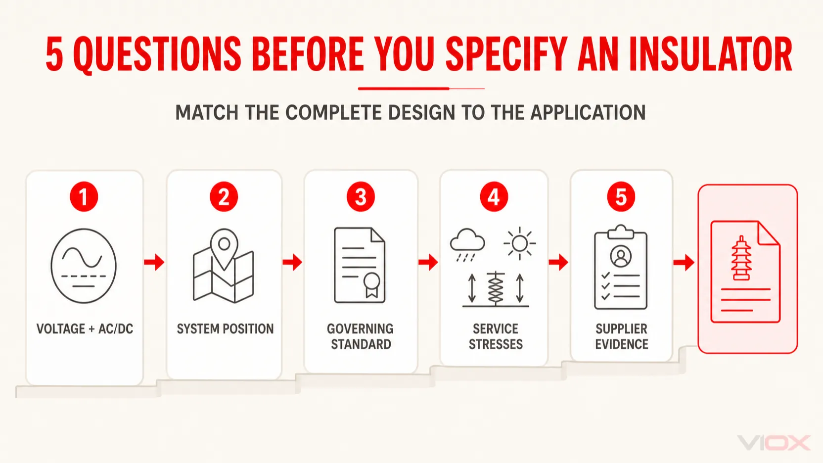
Before describing an insulator as HV or LV, answer these questions:
- What are the exact nominal voltage, maximum equipment voltage and AC/DC duty?
- Where is the insulator used—overhead line, substation, apparatus, switchgear, busbar system or control panel?
- Which product, equipment or assembly standard governs that position?
- What electrical, mechanical, pollution, altitude and environmental duties must be verified?
- Does the supplier’s evidence cover the exact construction and rating being specified?
If the application is a low-voltage panel or busbar assembly, continue with the VIOX busbar insulator selection guide and compare the relevant busbar insulator product family against the required dimensions, ratings and documentation. A high-voltage overhead-line or substation application requires the appropriate specialized insulator category and standard; it should not be sourced as a scaled-up panel support.
Frequently Asked Questions
Is 11 kV considered high voltage or medium voltage?
In everyday distribution engineering, 11 kV is commonly called medium voltage. Some IEC insulator and switchgear standards use “high voltage” broadly for equipment above 1,000 V. State “11 kV” and cite the governing standard rather than relying on the category name alone.
Can high- and low-voltage insulators use the same material?
Yes. Porcelain, epoxy and polymer systems can appear in different voltage classes. Suitability depends on the complete design, dimensions, interfaces, ratings and verified test evidence—not the material name alone.
Can a low-voltage insulator be used in a high-voltage system?
Not unless the exact component has ratings and evidence covering the actual high-voltage application. Physical fit or similar appearance does not demonstrate the required insulation level, creepage distance, mechanical performance or environmental suitability.
Do high-voltage insulators always have higher material dielectric strength?
No. System-voltage classification cannot be inferred from one dielectric-strength value. Complete insulator performance depends on material condition, thickness, geometry, surface path, interfaces, environment and the specified test method.
References
- IEC 60664-1:2020+AMD1:2025 — Insulation coordination for equipment within low-voltage supply systems
- IEC 60383-1:2023 — Ceramic or glass insulator units for AC overhead lines above 1,000 V
- IEC 61109:2025 — Composite suspension and tension insulators for overhead lines
- IEC TS 60815-1:2025 — Selection and dimensioning of high-voltage insulators in polluted conditions