On this page
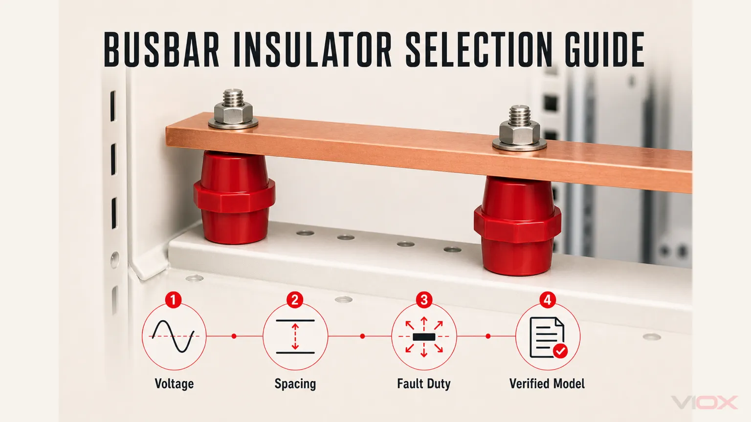
To choose the right busbar insulator, start with the installed assembly rather than a catalogue photo or a nominal voltage. Confirm the system voltage, creepage and clearance requirements, busbar dimensions, peak short-circuit current, unsupported span, operating environment, and mounting hardware before shortlisting a model.
A busbar insulator has two jobs: maintaining electrical separation and supporting the conductor mechanically. A model can satisfy one duty and still be unsuitable for the other. Voltage rating alone therefore does not establish that an insulator is safe for a particular panel layout.
For most indoor low-voltage distribution panels, a molded BMC or SMC busbar support insulator is the normal starting point. For harsh, humid, outdoor, high-pollution, or mechanically demanding applications, material and geometry must be reviewed more carefully.
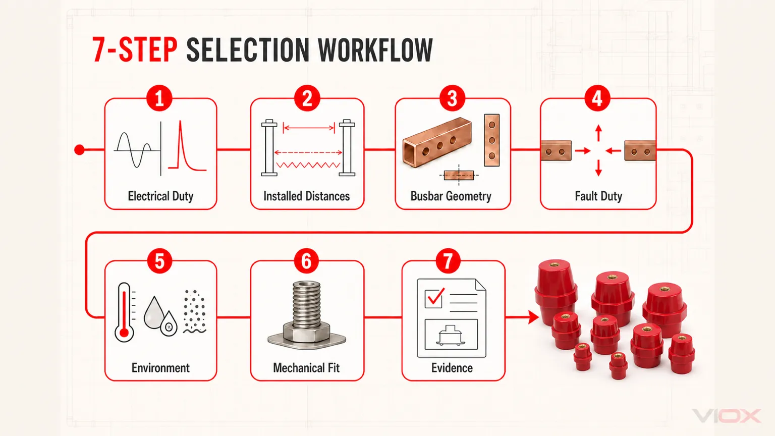
Busbar Insulator Selection in 7 Steps
Use this sequence to build a shortlist. Final approval still belongs to the complete busbar assembly, not the insulator as an isolated component.
| Step | What to Confirm | Selection Output |
|---|---|---|
| 1. Define electrical duty | Working voltage, insulation voltage, impulse withstand requirement, overvoltage category, and pollution degree | Required insulation performance and applicable design rules |
| 2. Establish installed distances | Phase-to-phase, phase-to-earth, busbar-to-enclosure clearance, and surface creepage path | Minimum acceptable height and profile in the actual geometry |
| 3. Record busbar geometry | Bar width, thickness, orientation, number of bars per phase, joints, bends, and tap-offs | Support type, footprint, and load direction |
| 4. Quantify fault duty | Peak short-circuit current, conductor spacing, unsupported span, and assembly withstand requirement | Mechanical force to be resisted by the support system |
| 5. Match the environment | Temperature, humidity, condensation, dust, salt, ultraviolet exposure, chemicals, and vibration | Suitable material, creepage profile, and enclosure strategy |
| 6. Check mechanical fit | Insulator height, body diameter, thread, stud length, busbar hole, washer, and tool access | Dimensionally compatible candidate models |
| 7. Verify evidence | Dimension drawing, material data, voltage test method, mechanical test direction, and model-specific report | Approved model rather than an unverified catalogue match |
For procurement, ask suppliers for a busbar insulator catalogue or size chart that includes height, thread size, rated voltage, material, mechanical strength, and dimensional drawings. A product photo alone is not enough for panel design.
Busbar Insulator Types at a Glance
Use the following as a selection map, not a complete type catalogue. For definitions and construction details, see What Is a Busbar Insulator?.
| Type | Common Search Term | What It Does | Best Fit |
|---|---|---|---|
| Standoff insulator | Busbar support insulator | Raises and supports the busbar above a grounded plate or frame | Low-voltage panels, distribution boards, control cabinets |
| Post insulator | Busbar post insulator | Provides taller and stronger vertical support | Switchboards, larger busbar systems, higher mechanical loads |
| Busbar holder insulator | Clamp-style busbar support | Holds a busbar in a fixed position with integrated support geometry | Compact busbar layouts, modular assemblies |
| Custom molded support | OEM busbar insulator | Combines insulation, support, and routing in one molded shape | OEM equipment and special busbar geometry |
If the conductor passes through a grounded partition or enclosure wall, select a suitable bushing separately. A bushing provides pass-through insulation rather than normal busbar support.
If you are comparing basic terms, VIOX also has a separate guide on standoff insulators vs busbar insulators. For product evaluation, see the VIOX busbar insulator product page.
Busbar Insulator Materials: BMC, SMC, Epoxy, Porcelain, and Polymer
Material choice affects tracking resistance, mechanical strength, temperature behavior, moisture resistance, and long-term reliability. This summary is intended only to narrow the candidate family; the definition guide above covers the materials in more detail.
| Material | Main Strength | Main Limitation | Typical Use |
|---|---|---|---|
| BMC | Cost-effective molded thermoset material with good mechanical and electrical performance | Quality depends heavily on formulation and molding process | Low-voltage panels, switchboards, standard busbar supports |
| SMC | Good strength and dimensional stability for molded parts | Usually used where the design suits sheet molding processes | Low-voltage support parts, larger molded structures |
| Epoxy | Strong dielectric performance and good moisture resistance when the formulation matches the application | Higher cost; brittleness, UV resistance, and outdoor durability depend on formulation | Engineered supports using an application-qualified epoxy system |
| Porcelain | Excellent tracking and UV resistance | Heavy and brittle; less convenient for compact panels | Outdoor, polluted, legacy, or special environments |
| Polymer composite | Lightweight and customizable; can offer hydrophobic surface behavior | Must be matched carefully to UV, heat, and chemical exposure | Outdoor or harsh environments, specialized designs |
For ordinary indoor low-voltage panels, BMC or SMC is often the most practical option. For coastal, outdoor, high-humidity, chemical, or high-pollution environments, review an outdoor-qualified epoxy system, porcelain, or a UV- and pollution-qualified polymer-composite material together with the enclosure strategy. Do not assume that a general-purpose indoor cast epoxy is suitable for sunlight, salt, condensation, or heavy pollution.
Material quality is also a supplier question. For a deeper inspection approach, see VIOX’s guide on how to determine the quality of a busbar insulator.
Manufacturer Quality Checks Buyers Should Ask About
From a manufacturer’s point of view, the difference between an engineering-grade busbar insulator and a cheap molded part is usually hidden in the material formulation, molding control, insert bonding, and final electrical testing.
For BMC and SMC molded insulators, ask the supplier how they control:
- Raw material formulation and glass-fiber reinforcement consistency
- Mold temperature, curing time, and dimensional tolerance
- Threaded insert alignment and pull-out strength
- Surface finish, flash removal, and void inspection
- Comparative Tracking Index (CTI) value and corresponding IEC material group, where applicable, or another stated tracking-resistance test basis
- Power-frequency withstand voltage or dielectric withstand test method
- Bending, tensile, compression, or cantilever strength data for the selected size
Do not accept “BMC material” as a complete specification. Two insulators can both be called BMC while having very different tracking resistance, mechanical strength, shrinkage control, and insert retention. For critical assemblies, request test reports or at least a datasheet that states the material grade, CTI value and IEC material group where applicable, voltage rating, and mechanical strength.
Busbar Support Insulator Size Chart
There is no universal busbar insulator size chart that works for every panel. The correct size depends on voltage, creepage distance, clearance, busbar weight, support span, short-circuit current, and mounting hardware.
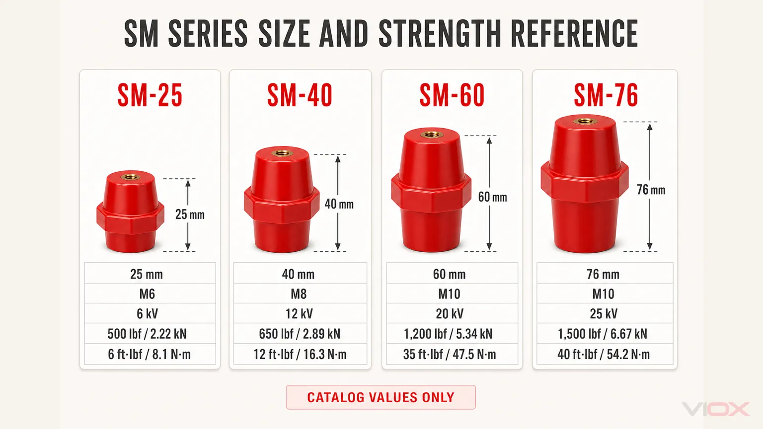
The selected values below show how height, thread, and published mechanical ratings can change within one product family. They are taken from the published VIOX SM Series busbar insulator page and must be checked against the current model drawing and datasheet before specification.
| Model | Height | Thread | Published withstand voltage | Published tensile strength | Published torque strength |
|---|---|---|---|---|---|
| SM-25 | 25 mm | M6 | 6 kV | 500 lbf / 2.22 kN | 6 ft·lbf / 8.1 N·m |
| SM-40 | 40 mm | M8 | 12 kV | 650 lbf / 2.89 kN | 12 ft·lbf / 16.3 N·m |
| SM-60 | 60 mm | M10 | 20 kV | 1,200 lbf / 5.34 kN | 35 ft·lbf / 47.5 N·m |
| SM-76 | 76 mm | M10 | 25 kV | 1,500 lbf / 6.67 kN | 40 ft·lbf / 54.2 N·m |
Catalog values only: The cited public product page does not specify the complete test waveform, frequency, duration, conditioning, or acceptance criteria. Request the model-specific test method and report before specification. Published tensile or torque values also do not automatically establish lateral, bending, cantilever, or complete-assembly short-circuit withstand.
The following chart is a practical reference for what to check when comparing catalogue sizes.
| Size Parameter | Common Options to Check | Why It Matters |
|---|---|---|
| Insulator height | Common low-voltage supports may use heights such as 20 mm, 25 mm, 30 mm, 40 mm, 50 mm, 60 mm or higher depending on design | Primarily affects busbar-to-ground or mounting-surface clearance; it may affect phase separation in stacked layouts |
| Thread size | M6, M8, M10, M12 or project-specific threads | Must match busbar hole size, washers, nuts, and mounting plate |
| Body diameter | Depends on voltage class and mechanical load | Affects bending strength and footprint |
| Base footprint | Round, hexagonal, rectangular, or custom base | Determines mounting space on the panel plate |
| Stud length | Short, standard, or extended | Must pass through busbar and hardware without bottoming out |
| Rated insulation voltage | Must match the assembly design | Voltage rating alone is not enough, but it is still the starting point |
| Creepage path | Ribbed or smooth profiles depending on application | Important in polluted or humid environments |
| Mechanical rating | Compression, tensile, bending, or cantilever strength | Must withstand busbar weight and fault forces |
When a buyer asks for a “busbar insulator size chart PDF,” the most useful document is not just a list of part numbers. It should include dimension drawings, thread details, material, rated voltage, mechanical strength, and recommended application range.
M6 vs M8 vs M10 vs M12 Threads
Thread size is a mechanical interface, not a simple indicator of voltage or current capacity. Match it to the busbar hole, washer system, mounting plate, required thread engagement, tightening method, and the load direction stated in the supplier’s mechanical data. Do not enlarge a busbar hole or substitute hardware on the assembly floor without checking the effect on contact area, edge distance, mechanical strength, and safe electrical spacing.
How to Choose Busbar Insulator Size
A good size decision follows the busbar layout, not the other way around.
1. Start with system voltage and insulation coordination
Check the system voltage, rated insulation voltage, impulse withstand requirement, overvoltage category, and pollution degree. In low-voltage switchgear assemblies, apply IEC 61439-1 together with the relevant assembly-specific part, such as IEC 61439-2 for power switchgear and controlgear assemblies where applicable. IEC 60664-1 insulation-coordination concepts are commonly relevant to creepage and clearance review. For assemblies destined for North America, the same busbar support layout may also need to be reviewed against the applicable UL framework, such as UL 508A for industrial control panels or UL 891 for switchboards, depending on the equipment category.
The important point is practical: the installed assembly must maintain the required air and surface distances after the busbar, fasteners, enclosure wall, adjacent phases, and covers are all in place.
2. Check busbar weight and support span
A longer unsupported span increases bending and vibration risk. A heavier copper busbar needs stronger and more frequent support. Copper busbar cross-section, number of bars per phase, horizontal or vertical orientation, and tap-off position all change the support duty.
For general busbar design context, see the VIOX busbar selection guide.
3. Review short-circuit forces
During a short-circuit event, parallel busbars can experience strong electrodynamic forces. The insulator must not crack, shift, loosen, or allow phase spacing to collapse under fault stress.
This is where many selections fail. The chosen support may look oversized for normal load but still be weak under fault force if support spacing, busbar orientation, or fastening is wrong.
For engineering review, the force between parallel conductors is often estimated from the short-circuit peak current, conductor spacing, and unsupported length. A simplified relationship is:
F_s = (μ_0 / 2π) × (i_p² / a) × lWhere:
F_sis the electrodynamic force on the busbar sectionμ_0is the magnetic permeability of free spacei_pis the peak short-circuit currentais the conductor center-to-center spacinglis the unsupported conductor length
The practical lesson is direct: force rises with the square of peak current. Doubling the peak fault current can create roughly four times the mechanical force. That is why high-fault-current panels need a support-spacing review, not just a stronger-looking insulator.
Screening limitation: This simplified expression represents an idealized two-conductor arrangement using center-to-center spacing. It does not include rectangular-conductor shape factors, three-phase interaction, fault type and instantaneous phase relationship, busbar orientation, dynamic structural response, or support-load distribution. Use IEC 60865-1, another validated engineering method, or complete-assembly test evidence for final verification.
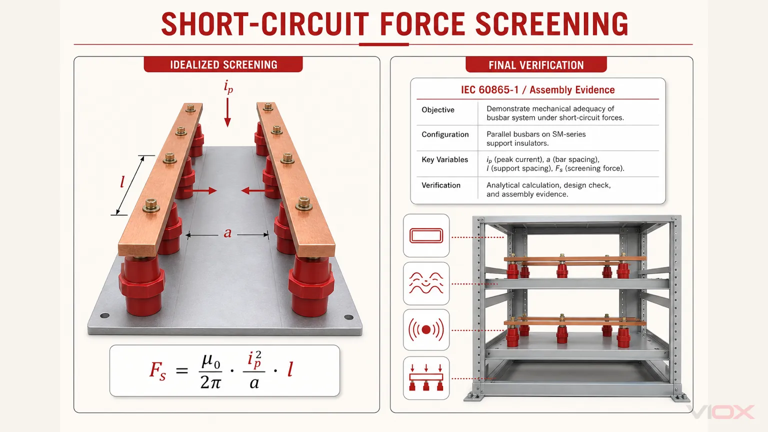
Final short-circuit withstand verification should be done at the complete assembly level, especially for IEC 61439 switchgear and controlgear assemblies.
4. Match thread size and hardware
A correct insulator with the wrong thread size becomes an assembly problem. Confirm the top and bottom threads, stud length, washer size, nut engagement, busbar hole diameter, and tightening access before ordering.
5. Confirm enclosure depth and service access
A taller post insulator may improve clearance but can conflict with enclosure depth, covers, or door-mounted devices. Make sure technicians can still reach and tighten the hardware after assembly.
Worked Screening Example: A 400 V Indoor Panel
Consider an indoor 400 V three-phase panel with parallel 40 x 5 mm rectangular copper busbars arranged in one plane, 50 mm center-to-center phase spacing, a proposed 300 mm unsupported span, M8 mounting hardware, and a 50 kA peak short-circuit current supplied by the assembly designer. Using the simplified parallel-conductor relationship above only as a first screening calculation:
F_s = 2 × 10⁻⁷ × (50,000² / 0.05) × 0.30 ≈ 3,000 NThis estimate shows why selecting only by 400 V operating voltage would be inadequate. The approximately 3 kN result indicates an order of magnitude for the idealized arrangement, not the design load of an insulator or bracket. The design review must account for rectangular-conductor geometry, three-phase interaction, dynamic response, and how reactions are distributed through the bars, fasteners, supports, and mounting structure.
Do not compare this calculated lateral force directly with a catalogue tensile value unless the supplier confirms that the test direction, fixture, load path, and failure criterion are applicable. The calculation is a screening tool; final short-circuit withstand remains a complete-assembly verification task.
Creepage Distance vs Clearance Distance
Busbar insulation failures often come from misunderstanding creepage and clearance.
| Term | Meaning | Why It Matters |
|---|---|---|
| Clearance | Shortest distance through air between conductive parts | Protects against flashover through air |
| Creepage | Shortest distance along an insulating surface | Protects against surface tracking, especially in humidity or pollution |
A taller insulator may improve clearance, but surface shape and material quality strongly affect creepage behavior. Ribbed profiles can increase creepage distance without increasing overall height, but the final result must be checked in the actual assembly.
For a deeper explanation, read VIOX’s creepage distance vs clearance distance guide.
Busbar Insulator Material and Environment
The environment can change the correct material choice.
| Environment | Risk | Selection Direction |
|---|---|---|
| Clean indoor panel | Normal electrical and mechanical duty | BMC or SMC molded support is often suitable |
| High humidity | Surface leakage and tracking | Review creepage distance, material CTI, and enclosure condensation control |
| Coastal or marine | Salt contamination becomes conductive when moist | Use material and profile suitable for pollution and corrosion risk |
| Outdoor UV exposure | Polymer surface degradation | Confirm UV resistance or use protected enclosure design |
| Chemical plant | Material attack by vapors or oils | Verify chemical resistance with the supplier |
| High vibration | Loosening and fatigue | Review mechanical strength, fasteners, locking method, and support span |
| High fault-current system | Electrodynamic force | Review short-circuit withstand design of the complete busbar support structure |
Indoor and outdoor applications should not use the same selection logic. If the installation is exposed to sunlight, salt, conductive dust, or condensation, see VIOX’s guide on indoor vs outdoor busbar insulators.
Copper Busbar Support Layout
The insulator does not work alone. It is part of the busbar support system.
When laying out copper busbars, check:
- Phase-to-phase spacing
- Phase-to-ground spacing
- Busbar-to-enclosure clearance
- Number of support points
- Support distance around joints and bends
- Tap-off locations
- Hardware access
- Thermal expansion path
- Cover and barrier fit
Short busbar runs may look mechanically simple, but concentrated loads near bends, cable lugs, breaker terminals, or transformer connections can overstress a support point. In compact distribution boards, the problem is often not voltage rating; it is a lack of space for correct spacing and hardware access.
If your system uses modular breaker busbars, the related article on circuit breaker busbars can help separate MCB busbar applications from larger busbar support structures.
Common Busbar Insulator Selection Mistakes
Mistake 1: Selecting by voltage rating only
A busbar insulator rated for the system voltage may still be wrong if it does not provide enough creepage distance, clearance, mechanical strength, or mounting compatibility in the final panel.
Mistake 2: Ignoring short-circuit force
Normal current creates heat. Fault current creates mechanical violence. A support that looks strong during normal operation may fail if the busbar spacing and support span were not designed for fault stress.
Mistake 3: Copying indoor material into outdoor applications
Moisture, salt, dust, and UV exposure can severely reduce surface insulation performance. Outdoor or polluted environments require a separate material and creepage review.
Mistake 4: Choosing a support that does not fit the hardware
Thread mismatch, insufficient stud length, poor washer fit, or limited tool access can force unsafe assembly-floor improvisation.
Mistake 5: Treating the size chart as a final answer
A size chart helps shortlist candidates. It does not replace creepage calculation, clearance review, mechanical load analysis, or approval of the complete panel layout.
Mistake 6: Forgetting documentation for procurement
For OEM or project buying, request dimension drawings, material information, rated voltage, mechanical strength data, and catalogue references. This prevents disputes between engineering, purchasing, and assembly teams.
For failure prevention, see VIOX’s article on common busbar insulator failures.
Busbar Insulator Specification Checklist
Use this checklist before approving a model.
| Item | Required Confirmation |
|---|---|
| Application | Distribution panel, switchboard, inverter cabinet, battery cabinet, OEM equipment |
| System voltage | Working voltage, insulation voltage, impulse withstand requirement |
| Standard context | IEC 61439-1 plus the applicable assembly-specific part and IEC 60664-1 where relevant; UL 508A or UL 891 review for applicable North American assemblies |
| Support type | Standoff, post, support block or holder, or custom molded support; specify a bushing separately for a grounded-barrier penetration |
| Material | BMC, SMC, epoxy, porcelain, or polymer composite |
| Size | Height, diameter, base footprint, stud length |
| Thread | M6, M8, M10, M12 or project-specific |
| Busbar data | Width, thickness, material, number of bars per phase, orientation |
| Support layout | Span length, number of supports, tap-off position, joint location |
| Environment | Temperature, humidity, dust, salt, UV, chemical exposure |
| Mechanical duty | Static load, vibration, transport shock, short-circuit force |
| Documentation | Catalogue, size chart, drawing, material data, mechanical data |
FAQ
How do I choose busbar insulator size?
Choose the size based on voltage, creepage distance, clearance, busbar weight, support span, short-circuit force, thread size, enclosure depth, and hardware access. Do not choose by height alone.
Is there a universal busbar insulator size chart?
No. A size chart is useful for comparing height, thread size, and dimensions, but the correct selection depends on the complete busbar layout and operating conditions.
How far apart should busbar insulators be installed?
There is no universal support spacing. It depends on busbar dimensions and orientation, peak short-circuit current, phase spacing, joint and tap-off locations, vibration, and the mechanical ratings of the complete support structure. Determine spacing through calculation and assembly verification rather than copying a fixed distance from another panel.
Can I select a busbar insulator from voltage rating alone?
No. The installed creepage and clearance, material behavior, mechanical load, fault force, thread interface, support span, and environment must also be suitable. A catalogue voltage value does not represent all these conditions.
How should mechanical strength ratings be compared?
Compare ratings only when the load direction, test fixture, conditioning, duration, and failure criterion are stated. Tensile, compression, torque, bending, and cantilever ratings are not interchangeable, and none automatically proves complete-panel short-circuit withstand.
Which thread size should I choose: M6, M8, M10, or M12?
Use the thread specified by the approved mechanical interface. Check the busbar hole, washer and nut system, thread engagement, stud length, mounting-plate design, tightening access, and supplier load data. A larger thread does not by itself prove a higher electrical rating.
Can the same busbar insulator be used indoors and outdoors?
Not always. Outdoor environments may involve UV, moisture, salt, and pollution. These conditions can require different material, creepage profile, or enclosure protection.
Conclusion
The right busbar insulator is not simply the one with the correct voltage printed in the catalogue. It must fit the electrical insulation duty, mechanical support duty, busbar layout, environmental condition, and mounting hardware of the complete assembly.
Use the seven-step process in this guide to document the electrical duty, installed distances, busbar geometry, fault duty, environment, mechanical fit, and supporting evidence before approving a model.
If those answers are documented before purchasing, the busbar support system is far less likely to create assembly delays, connection stress, insulation failure, mechanical displacement, or field-service problems.
Sources and Standards
- IEC 60664-1:2020+AMD1:2025 CSV — Insulation coordination for equipment within low-voltage supply systems
- IEC 60865-1:2011 — Short-circuit currents: calculation of mechanical and thermal effects
- IEC 61439-1:2020 — Low-voltage switchgear and controlgear assemblies: general rules
- IEC 61439-2:2020 — Power switchgear and controlgear assemblies
- VIOX SM Series Busbar Insulator — published model data
For model selection support, send VIOX the system voltage, busbar dimensions and orientation, peak short-circuit current, conductor center spacing, proposed support span, installation environment, thread requirement, and applicable assembly standard. VIOX can then help identify candidate models and the drawings or test evidence that still require project approval.