On this page
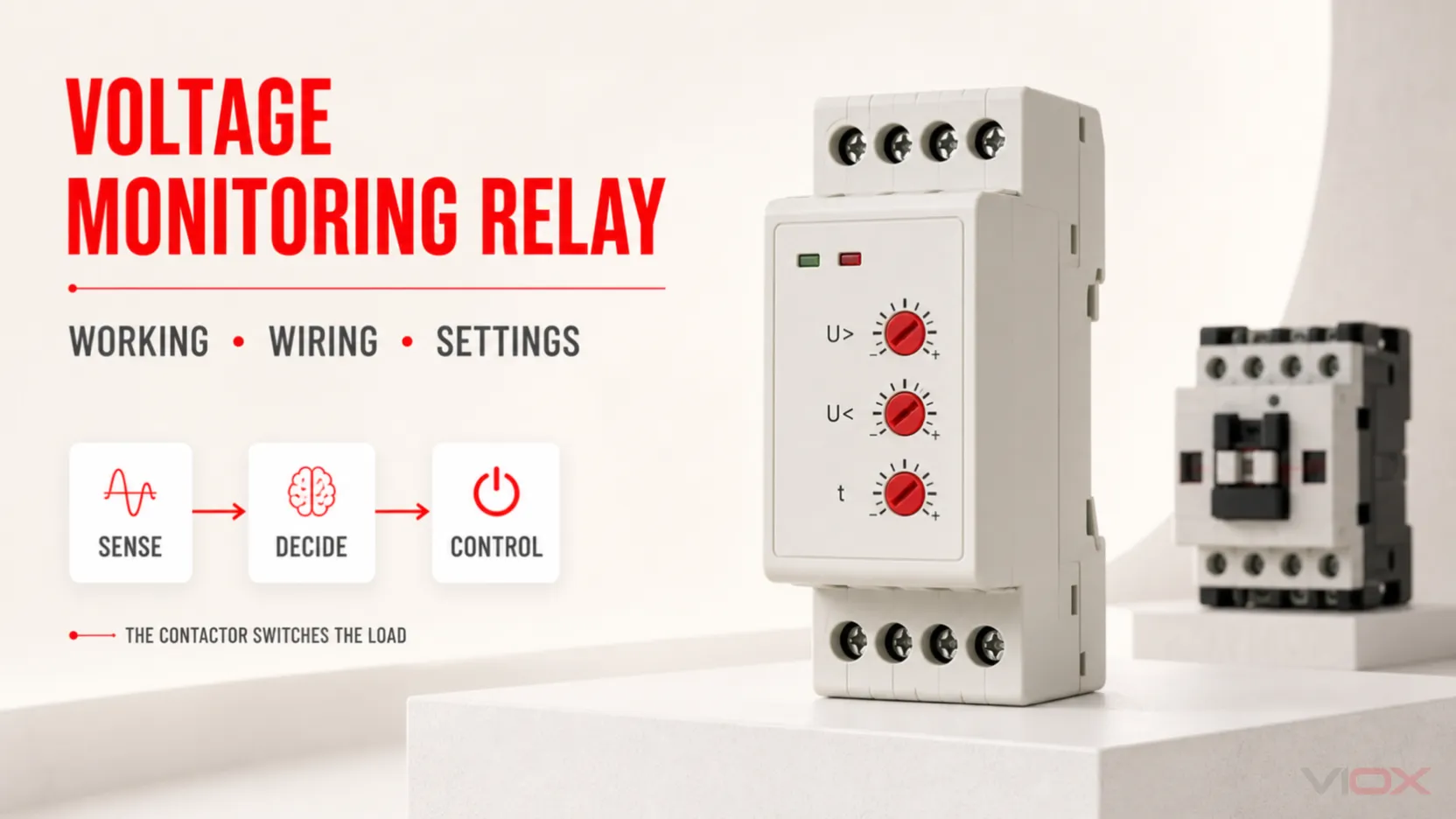
A voltage monitoring relay measures an AC or DC supply and changes its output contact when a configured condition occurs. Depending on the exact model, it may detect undervoltage, overvoltage, phase loss, incorrect phase sequence, or voltage imbalance. The relay normally does not disconnect a motor or feeder directly. Instead, its output contact controls a contactor coil, circuit-breaker trip input, programmable logic controller (PLC) input, alarm, or interlock that performs the required action.
Correct application therefore requires three separate decisions: what voltage is measured, what condition changes the relay output, and what external device acts on that signal.
Key Takeaways
- A monitoring relay is a measuring and control device, not normally a power switching device.
COM,NC, andNOdescribe contacts in their normal, de-energized state; the healthy-state logic still depends on the relay’s operating principle.- Common IEC-style changeover terminal numbers include
11-12-14or15-16-18, but the exact datasheet and diagram always take priority. - Single-phase devices commonly sense
L-N,L1-L2, or+/-, depending on the model and circuit. - Three-phase devices commonly sense
L1-L2-L3; a neutral connection is required only for models and functions designed forL1-L2-L3-Nsystems. - Phase loss in a running three-phase motor can cause damaging single-phasing, overcurrent, and overheating. The normal protective response is to stop or prevent starting the equipment.
- Threshold, hysteresis, delay, memory, and reset settings must match the load and system behavior—not a universal internet value.
What Is a Voltage Monitoring Relay?
A voltage monitoring relay is an industrial control device that supervises one or more voltages and provides a discrete output when the measured condition is healthy or faulty. It is often DIN-rail mounted inside a control panel, although other mounting formats exist.
The product category includes several different functions:
| Monitoring function | What it evaluates | Typical control response |
|---|---|---|
| Undervoltage | Voltage below a configured lower threshold | Drop out a contactor, block a start, or raise an alarm after any delay |
| Overvoltage | Voltage above a configured upper threshold | Change the control output or signal a supervisory system |
| Phase loss | One phase absent or below the device’s detection criterion | Stop or inhibit a three-phase load |
| Phase sequence | Incorrect order of L1, L2, and L3 | Prevent a direction-sensitive motor from starting |
| Voltage imbalance | Difference between phase voltages exceeds a configured limit | Stop or alarm before prolonged unbalanced operation |
| Window monitoring | Voltage must remain between lower and upper limits | Keep the output in its healthy state only inside the accepted window |
Not every monitoring relay performs every function. Omron’s K8AK-PM family, for example, is described for three-phase voltage, phase sequence, and phase-loss monitoring, while ABB offers different three-phase variants with combinations of overvoltage, undervoltage, phase failure, imbalance, and sequence monitoring. Selection must begin with the exact functions required.
Voltage Monitoring Relay Working Principle
The practical working principle can be divided into three layers.
1. Measurement
The sensing terminals are connected to the electrical quantity that must be supervised. A single-phase device may measure line-to-neutral, line-to-line, or DC voltage. A three-phase device may measure phase-to-phase voltages, phase-to-neutral voltages, or both, depending on its circuit and wiring-system configuration.
Some relays are powered directly from the measured circuit. Others use separate supply terminals such as A1/A2 and separate measurement inputs. This distinction affects what happens if the measurement circuit or the auxiliary control supply disappears.
2. Evaluation
Internal electronics compare the measured value with the configured criteria. The logic may include:
- one undervoltage threshold;
- one overvoltage threshold;
- an upper and lower window;
- phase-sequence or phase-loss detection;
- an imbalance threshold;
- start-up, trip, or recovery delays;
- hysteresis between trip and reset points;
- automatic reset or latched/manual-reset behavior.
The front-panel LEDs or display may indicate supply, relay status, measured voltage, or a fault code. The meaning of each indication is model-specific.
3. Output action
After the fault condition satisfies the configured timing logic, the relay changes its output contact state. That dry contact then switches a control circuit. It may de-energize a contactor coil, signal a PLC, energize an alarm, or operate an approved breaker trip circuit.
This separation matters. The monitoring relay contact must be rated for the control load and utilization category, but it is not automatically rated to switch the protected motor or feeder current.
Output Contact Logic: COM, NC, and NO
A single-pole double-throw (SPDT) output has three terminals:
| Contact | Meaning in the normal, de-energized state | Common IEC-style examples |
|---|---|---|
| COM | Common moving contact | 11 or 15 |
| NC | Normally closed to COM | 12 or 16 |
| NO | Normally open from COM | 14 or 18 |
For a common 11-12-14 changeover contact:
Relay de-energized:
11 COM ─── 12 NC     closed
11 COM     14 NO     open

Relay energized:
11 COM     12 NC     open
11 COM ─── 14 NO     closed
The words “normal,” “NO,” and “NC” refer to the de-energized mechanical state—not automatically to “supply healthy” or “fault.” To know which contact closes during healthy operation, read the function diagram.
Closed-circuit principle
Many protection-oriented applications energize the output relay while the monitored supply is healthy. A persistent fault causes the output to de-energize. ABB documents this closed-circuit principle for its CM-PFS phase-monitoring relay: correct phases energize the outputs after the start-up delay, while phase failure or incorrect sequence de-energizes them.
This architecture can be fail-aware because loss of control power, loss of monitoring power, a broken control conductor, or a detected voltage fault can all release the contactor. The complete control circuit must still be engineered so that the resulting state is safe for the machine.
Open-circuit principle
Some devices or selected functions energize an output when the fault occurs. This can be appropriate for an alarm signal, but loss of relay supply may then leave the fault output inactive. Do not infer the operating principle from the terminal numbers alone.
Single-Phase Voltage Monitoring Relay Wiring Diagram
The following is a generic control concept, not a substitute for a product diagram.
MONITORED SUPPLY

Line / L1  ───────────── relay sensing input L or L1
Neutral / L2 ─────────── relay sensing input N or L2

CONTROL OUTPUT TO CONTACTOR

Control line ── fuse ── COM (11 or 15)
                           |
                      healthy-state NO
                         (14 or 18)
                           |
                       A1 contactor coil
A2 contactor coil ───── control neutral / return

POWER CIRCUIT

Supply ── protective device ── contactor main contacts ── load
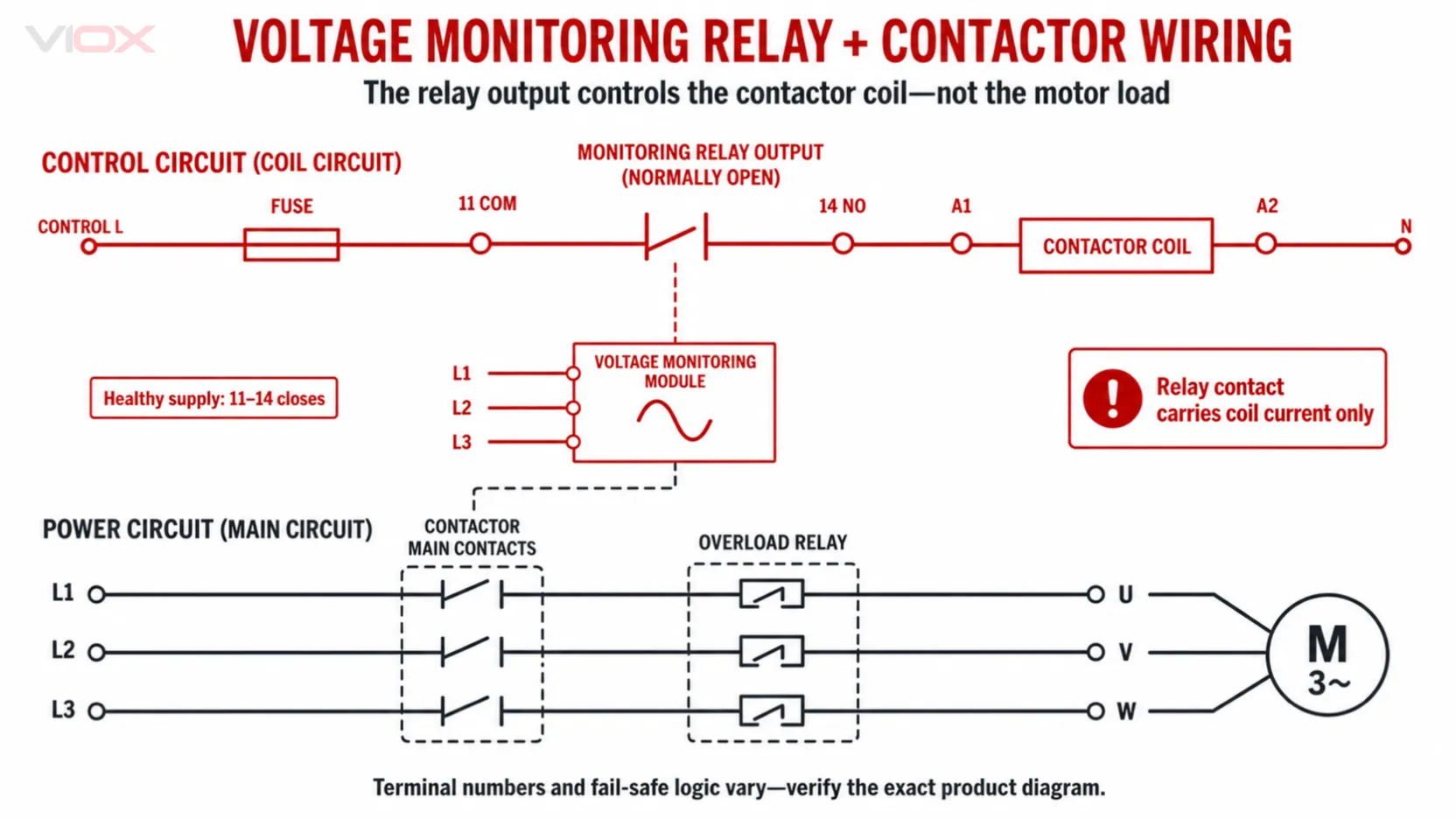
In this common closed-circuit arrangement, the monitoring relay’s healthy-state contact completes the contactor coil circuit. If voltage moves outside the permitted window for longer than the configured delay, the monitoring output releases and the contactor opens the load circuit.
Before wiring, answer these questions from the exact datasheet:
- Does the device measure
L-N,L1-L2, or DC+/-? - Is the device self-powered by the measuring circuit, or does it need
A1/A2auxiliary power? - Which output pair is closed when the monitored voltage is healthy?
- Is the output contact suitable for the contactor coil voltage, inrush, and utilization category?
- Does the relay automatically reset after voltage recovery, or does the control circuit require a manual restart?
Do not assume that every single-phase relay is limited to 230 V. Product ranges include different AC and DC measurement bands; select the actual model from the system voltage and required thresholds.
Three-Phase Voltage Monitoring Relay Wiring Diagram
A typical three-phase monitoring relay senses the phases upstream of the contactor so it can prevent starting when the incoming supply is unhealthy and drop out the contactor if a monitored fault develops.
POWER CIRCUIT

L1 ── short-circuit protection ── contactor pole 1 ── overload relay ── motor U
L2 ── short-circuit protection ── contactor pole 2 ── overload relay ── motor V
L3 ── short-circuit protection ── contactor pole 3 ── overload relay ── motor W

MONITORING INPUTS

L1 ───────────────────────────── monitoring relay L1
L2 ───────────────────────────── monitoring relay L2
L3 ───────────────────────────── monitoring relay L3
N  ───────────────────────────── monitoring relay N, only when required

CONTACTOR CONTROL

Control supply ── stop/control permissives ── overload NC ── relay healthy contact
                ── start / seal-in logic ── A1 contactor coil
A2 contactor coil ─────────────────────── control return
Important boundaries:
- A three-wire relay designed for
L1-L2-L3must not be converted into a four-wire measurement scheme by improvisation. - A four-wire
L1-L2-L3-Ndevice may use neutral for supply, phase-to-neutral measurement, or both. Follow its diagram. - Correct phase sequence is determined by the order at the relay sensing terminals. Swapping two phases changes the detected sequence.
- Phase loss can be harder to detect after a motor is running because a rotating motor can generate a reverse-fed voltage on the missing phase. Use a relay whose stated phase-loss behavior fits the application.
- Loss of one phase is not a continuity advantage for a three-phase motor. Continued single-phasing can produce excessive current and heating, so the usual objective is rapid stop or start inhibition.
For model-specific three-phase functions and wiring-system options, see the VIOX FCP18 three-phase voltage monitoring relay guide.
How a Voltage Monitoring Relay Controls a Contactor
The contactor separates the low-power decision circuit from the power circuit.
MEASUREMENT          DECISION              ACTION
L1/L2/L3 or L/N  →  monitoring relay  →  COM/NO/NC contact
                                             ↓
                                      contactor coil A1/A2
                                             ↓
                                      main power contacts
                                             ↓
                                            load
The monitoring relay output is commonly placed in series with the contactor coil and ordinary control permissives, such as a stop pushbutton, overload-relay NC contact, pressure switch, or PLC output. Every required condition must be healthy before the coil can energize. Any emergency-stop or other safety-related function must retain the architecture, components, diagnostics, and performance level required by the machine safety design; a standard monitoring relay is not a safety relay.
When selecting the interface:
- match the contactor coil voltage to the control supply;
- verify the monitoring relay’s contact rating for the coil’s AC or DC utilization duty, not only a resistive ampere value;
- use an interface relay where the monitoring contact cannot switch the coil directly;
- consider suitable coil transient suppression, especially for DC coils, without compromising required release time;
- preserve manual start and anti-automatic-restart behavior where the machine risk assessment requires it;
- do not use the monitoring contact as a substitute for an emergency-stop safety circuit or safety-rated protective function.
For the power-switching side, the VIOX guide to modular contactor wiring explains A1/A2 coil terminals and main-contact separation in more detail.
What Faults Can a Voltage Monitoring Relay Detect?
Overvoltage and undervoltage
The relay compares voltage with an upper threshold, lower threshold, or both. A voltage excursion must usually persist for the configured trip delay before the output changes, although some severe or special faults may have a separate response rule.
Phase loss
Phase-loss monitoring detects an absent or sufficiently reduced phase according to the product’s measurement method. For motors, the goal is normally to prevent starting or stop operation before single-phasing produces damaging current and temperature conditions.
Incorrect phase sequence
A phase-sequence relay verifies the order of the three phase inputs. An incorrect sequence can reverse a direction-sensitive motor. The relay typically prevents the contactor from energizing until the input order is corrected.
Voltage imbalance or asymmetry
An imbalance function compares the phase voltages using the model’s stated calculation method. If the calculated asymmetry exceeds the configured limit for the required delay, the output changes state. Do not assume every three-phase relay measures imbalance, or that all manufacturers use an identical formula.
What it does not replace
A standard voltage monitoring relay does not automatically provide:
- motor overload or locked-rotor protection;
- short-circuit protection;
- surge protection;
- residual-current or ground-fault protection;
- insulation monitoring;
- safety relay functions;
- battery cell balancing or a battery management system (BMS);
- grid-code interface protection for a generating plant;
- electric-vehicle battery control or high-voltage interlock loop logic.
Some specialized devices combine several functions, but the exact datasheet and certification scope must establish them.
Threshold, Hysteresis, Trip Delay, and Reset Settings
Settings should be derived from the equipment’s permitted voltage range, the supply behavior, process risk, and the monitoring relay’s functions.
Threshold
The threshold is the voltage or percentage at which the relay recognizes a fault condition. A window relay has both lower and upper thresholds. Use the protected equipment specification and applicable design requirements; do not copy a generic setting without checking the nominal voltage and load tolerance.
Hysteresis
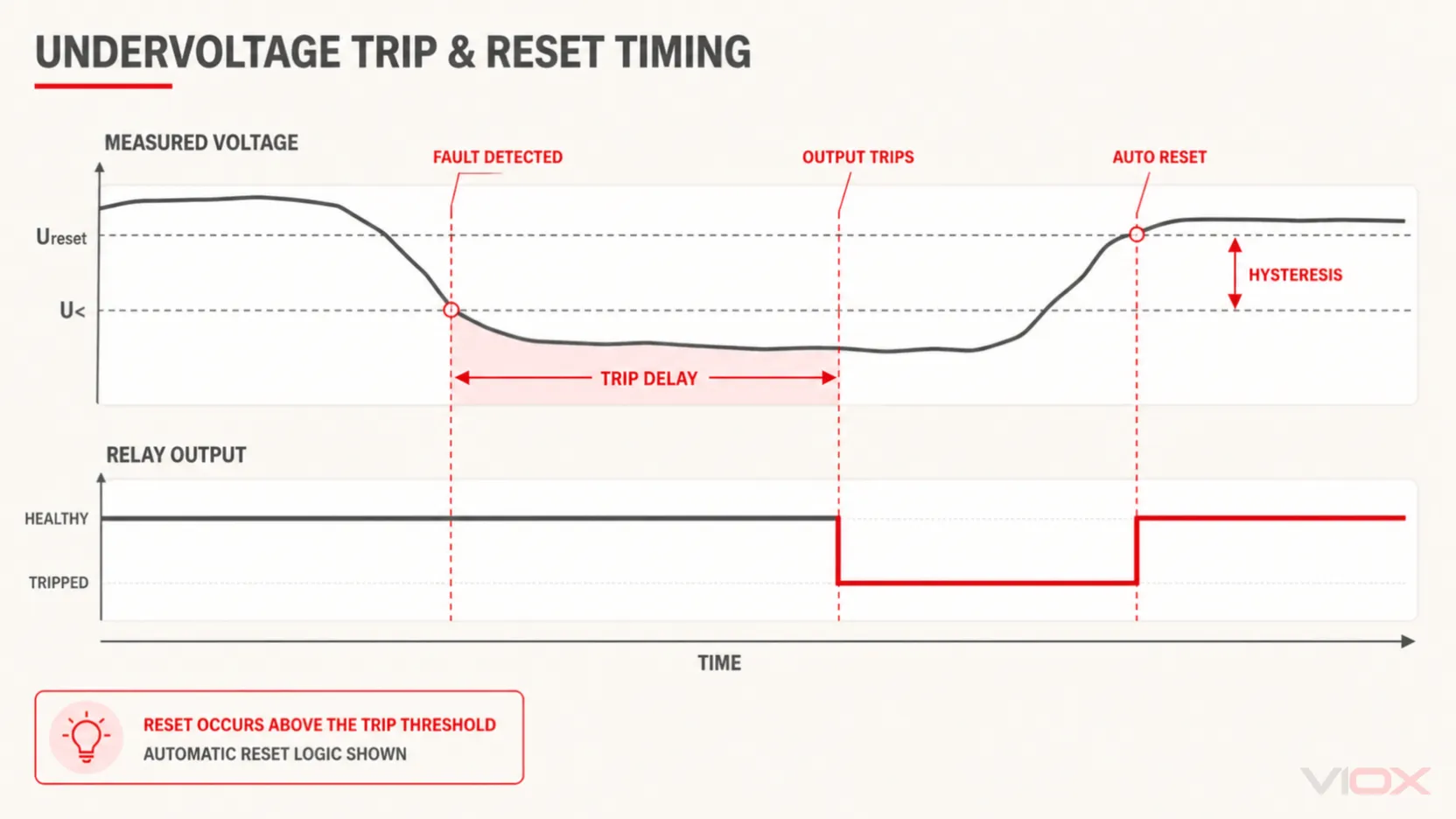
Hysteresis separates the trip point from the recovery point, preventing repeated switching when voltage fluctuates near a threshold.
Illustrative example only:
Undervoltage trip threshold = 90 V
Reset hysteresis = 10 V
Trip when voltage falls to the threshold under the configured logic
Reset only after voltage recovers to 100 V
The actual relay may express hysteresis as volts, a percentage of threshold, or a percentage of nominal voltage. Schneider Electric’s RM22UA guidance demonstrates the same principle: the recovery level is offset from the trip threshold so small fluctuations do not cause repeated trip/reset cycles.
Trip delay
A trip delay filters short disturbances. Too little delay can cause nuisance stops; too much delay can expose the load to an unacceptable condition. Some relays provide different delays for overvoltage, undervoltage, imbalance, start-up, or recovery. Phase loss and incorrect sequence may use a fixed or immediate response on certain products.
Start-up or energization delay
This delay allows the supply to stabilize after power is applied before the output enters its healthy state. It is different from the delay applied after a running system crosses a fault threshold.
Automatic reset
With automatic reset, the relay returns to its healthy output state after voltage recovers past the reset boundary and any recovery delay expires. If the contactor circuit permits automatic restart, the load may start again without an operator command. Decide whether that behavior is acceptable before using it.
Manual reset or memory
A latching or memory function retains the fault until a reset command is given. Not every monitoring relay includes this function. Manual restart can also be implemented in the external contactor control circuit even when the monitoring relay itself automatically resets.
Single-Phase vs Three-Phase Monitoring Relays
| Selection point | Single-phase relay | Three-phase relay |
|---|---|---|
| Typical inputs | L-N, L1-L2, or DC +/-, depending on model |
L1-L2-L3 or L1-L2-L3-N |
| Core functions | Overvoltage, undervoltage, or window monitoring | Voltage limits plus model-dependent phase loss, sequence, and imbalance |
| Typical loads | Control supplies, single-phase pumps, compressors, HVAC, sensitive equipment | Three-phase motors, pumps, fans, compressors, conveyors, machine feeders |
| Main selection risk | Wrong measurement or supply range | Wrong wiring system, missing neutral requirement, or missing phase function |
| Voltage limit | Defined by exact model; not universally 230 V | Defined by exact model; not universally 415 V |
ABB’s current range information illustrates why fixed voltage definitions are unreliable: its CM-MPS/N three-phase family includes rated voltage levels up to 820 V AC. That does not make every ABB or VIOX relay suitable for that voltage; it shows that the product model, not the words “single phase” or “three phase,” determines the measurement range.
AC vs DC Voltage Monitoring Relays
An AC monitoring relay may use RMS measurement, frequency-related logic, or phase functions. A DC monitoring relay observes polarity-defined DC voltage and may be intended for control supplies, telecom systems, battery-backed control circuits, or other bounded DC applications.
Check these points before selecting an AC/DC or DC model:
- measured voltage type and range;
- polarity requirements;
- whether measuring and supply circuits share a common reference;
- maximum continuous measurement voltage;
- upper/lower threshold range;
- output contact AC and DC switching ratings;
- reset and memory behavior;
- isolation between measurement, supply, and output circuits;
- application-specific approvals or equipment requirements.
A simple DC undervoltage relay may supervise overall bus voltage, but it is not a BMS. It does not establish cell-level monitoring, balancing, temperature protection, state-of-charge calculation, contactor diagnostics, or functional-safety behavior unless the product documentation explicitly says so.
Where to Use a Voltage Monitoring Relay
Use a voltage monitoring relay when an equipment control decision depends on the quality or arrangement of the incoming voltage and the main switching is performed by another suitable device.
Typical applications include:
- Motor control panels: prevent starting or stop a motor for phase loss, incorrect sequence, unacceptable voltage, or imbalance, while an overload relay handles motor overcurrent.
- Pumps and compressors: inhibit operation during unstable supply conditions and coordinate with pressure, level, or process controls.
- HVAC equipment: supervise three-phase compressor, fan, and pump supplies through the contactor control circuit.
- Conveyors and machine tools: block operation if phase order would produce reverse rotation or if the supply is outside the equipment limits.
- Automatic transfer and generator control: provide a voltage-healthy input to the transfer or controller logic when the device and system design support that use.
- Control power supervision: signal a PLC or alarm when an AC or DC control supply moves outside its accepted window.
- Building and industrial distribution panels: provide a dry-contact alarm or permissive for a supervised feeder or equipment group.
For solar, storage, EV charging, or generator-grid interfaces, do not assume a generic voltage relay satisfies application-specific grid, anti-islanding, battery, automotive, or functional-safety requirements. Use equipment designed and approved for the actual system function.
Voltage Monitoring Relay Selection Checklist
| Selection item | Question to answer | Evidence required |
|---|---|---|
| System | Single phase, three-phase three-wire, three-phase four-wire, or DC? | Electrical diagram and nominal system data |
| Measurement range | What minimum and maximum voltage can appear? | System tolerances and exact relay datasheet |
| Monitoring functions | Under/overvoltage, phase loss, sequence, imbalance, or window? | Equipment risk assessment and function table |
| Supply architecture | Self-powered or separate auxiliary supply? | Terminal diagram and control-power design |
| Output logic | Healthy-energized, fault-energized, or selectable? | Function/timing diagram |
| Output contact | Can it switch the contactor coil or input duty? | AC/DC utilization rating and coil data |
| Settings | What thresholds, hysteresis, and delays are required? | Equipment limits and commissioning plan |
| Reset | Automatic, manual, remote, or external restart logic? | Process safety and restart requirements |
| Indication | Which fault and relay states must be visible or reported? | Operator and PLC/SCADA requirements |
| Standards | Which product standard, listing, or project approval applies? | Exact certificate and adopted project requirements |
| Installation | DIN space, terminals, enclosure, temperature, altitude, and wiring? | Manufacturer installation instructions |
Do not approve a substitute only because its voltage range and contact count appear similar. The operating principle, phase functions, output timing, terminal arrangement, and approvals may differ.
Commissioning Procedure
Only qualified personnel should work on energized electrical equipment. Isolate the installation and verify absence of voltage before changing wiring.
- Confirm the model: Check the complete part number, measuring range, supply type, phase configuration, output contact, and intended function.
- Verify wiring against the exact diagram: Confirm sensing terminals, auxiliary supply, neutral requirements, COM/NC/NO assignments, and contactor coil circuit.
- Record the settings: Document thresholds, hysteresis, start-up delay, trip delay, reset mode, and any memory function.
- Check the healthy state: Apply a known acceptable supply and verify LEDs, displayed values, output contact state, and contactor behavior.
- Test each required fault: Use an approved test method or source to simulate undervoltage, overvoltage, phase loss, incorrect sequence, or imbalance as applicable. Do not create unsafe live faults by removing conductors under load.
- Measure response and recovery: Verify that trip and reset occur at the intended levels and after the intended delays.
- Verify restart behavior: Confirm whether the machine remains stopped, automatically restarts, or requires an operator command after voltage recovery.
- Restore and document: Return all test connections to normal, secure settings where possible, and record results for maintenance.
Troubleshooting a Voltage Monitoring Relay
| Symptom | Likely cause | What to check | Corrective direction |
|---|---|---|---|
| Relay has no indication | Missing supply, wrong voltage model, blown control fuse, or wrong A1/A2 connection | Measure supply at the specified terminals and compare with nameplate | Restore correct control supply or correct the model/wiring |
| Relay shows healthy but contactor will not energize | Wrong NO/NC pair, open stop/overload circuit, wrong coil voltage, or inadequate output rating | Trace voltage through COM and healthy contact to A1; check A2 return | Correct the control circuit; use an interface relay if required |
| Contactor drops out repeatedly | Voltage near threshold, too little hysteresis, delay too short, loose connection, or unstable supply | Record all phase voltages and output state over time | Correct the supply/connection or adjust settings within equipment limits |
| Phase fault remains after wiring looks correct | Incorrect phase order, missing neutral on a four-wire model, wrong nominal-voltage version, or reverse-fed motor voltage | Compare terminal order and measured voltages with the function diagram | Correct phase order/model/wiring; verify phase-loss detection suitability |
| Relay never trips during a test | Wrong monitored terminals, disabled function, threshold outside test range, excessive delay, or output logic misunderstood | Verify actual measured value, settings, timing mode, and contact state | Correct configuration and repeat with an approved test method |
| Load restarts unexpectedly after voltage recovery | Automatic reset plus a maintained contactor command | Review relay reset mode and seal-in/control logic | Add manual restart or latching logic where required by risk assessment |
| PLC alarm is inverted | NO/NC input selected incorrectly or PLC logic assumes the opposite healthy state | Test input with relay energized, de-energized, and unpowered | Choose fail-aware contact logic and update PLC documentation |
If the relay behaves correctly by itself but the equipment does not respond, separate the diagnosis into measurement input, relay logic, output contact, contactor coil, main power contacts, overload protection, and load. Testing the whole chain as one device often hides the actual fault.
Frequently Asked Questions
What does a voltage monitoring relay do?
It measures a specified AC or DC voltage condition and changes a control output when the configured healthy or fault criteria are met. Depending on the model, it may monitor under/overvoltage, phase loss, phase sequence, or imbalance.
Does a voltage monitoring relay disconnect the load directly?
Usually not. A DIN-rail monitoring relay generally changes a dry control contact. A contactor, breaker trip circuit, PLC, or other external device performs the main switching action. Direct switching is permissible only when the exact output contact is rated and approved for that load duty.
How do I wire terminals 11, 12, and 14?
In a common IEC changeover convention, 11 is COM, 12 is NC, and 14 is NO. Other relays may use 15-16-18 or different numbering. Verify the diagram printed on the exact device before wiring.
Should the contactor use the NO or NC relay contact?
It depends on the relay operating principle and required safe state. Many closed-circuit protection designs use the contact that is closed only while the relay is powered and the supply is healthy, so a fault or loss of relay power releases the contactor. Confirm the function diagram rather than choosing by the letters alone.
Where should L1, L2, and L3 be connected?
Connect them to the correspondingly marked measurement terminals in the phase order required by the exact relay. A neutral is connected only if the model and wiring diagram require it.
What is hysteresis in a voltage monitoring relay?
Hysteresis is the separation between the trip and reset conditions. It prevents repeated output switching when voltage fluctuates close to a threshold.
What is the difference between trip delay and start-up delay?
Trip delay is the time a detected fault must persist before the output changes. Start-up delay is the time after energization before the relay enters its normal healthy output state. A product may provide one, both, or different delays for different functions.
Will a three-phase motor continue running after phase loss?
It may continue rotating due to single-phasing and reverse-fed voltage, but this can cause damaging current imbalance and overheating. A phase-monitoring relay is generally used to stop or inhibit the motor, not to justify continued operation.
Can I use a voltage monitoring relay for a battery or EV system?
A suitably rated DC relay may supervise overall DC voltage for a bounded control function. It does not replace a BMS, cell monitor, EV controller, high-voltage interlock, insulation monitor, or safety system unless its documentation explicitly covers that function.
Conclusion
A voltage monitoring relay is most useful when it is treated as one link in a control chain. It measures the supply, evaluates a defined fault, and changes a control contact. The external contactor, PLC, alarm, or approved trip circuit then acts on that output.
Successful selection depends on the wiring system, voltage range, monitored faults, output logic, contact duty, settings, reset behavior, and model-specific terminal diagram. Do not use fixed 230 V or 415 V assumptions, and do not extend a standard DIN-rail relay into BMS, EV, grid-protection, or safety functions it was not designed to perform.
For a three-phase application, continue with the VIOX FCP18 function and selection guide or review the VIOX FCP18 product page against the exact system voltage, wiring configuration, required fault functions, delay, output use, and target-market documentation.