
Why Your 400A Switchgear Trips at 350A: The Hidden Truth About Current Ratings
Picture this: You’ve specified a distribution board with a 400A main circuit breaker for an industrial facility. The load calculations show 340A maximum demand—well within capacity. Yet three months after commissioning, the system trips repeatedly under continuous operation at just 350A. The client is furious, production is halted, and you’re scrambling to understand what went wrong.
The culprit? A fundamental misunderstanding of how IEC 61439 defines current ratings. Unlike traditional “breaker rating” thinking—where a 400A breaker equals 400A capacity—the modern standard treats switchgear as an integrated thermal system. Three critical parameters govern real-world capacity: InA (assembly rated current), Inc (circuit rated current), and RDF (rated diversity factor).
This guide decodes these interconnected ratings to prevent costly specification errors. Since IEC 61439 replaced IEC 60439 in 2009 (with transition periods ending by 2014), these parameters have become mandatory for compliant switchgear assemblies. Yet confusion persists, particularly around RDF—a thermal derating factor often mistaken for electrical diversity.
Whether you’re a panel builder, consulting engineer, or distributor, understanding InA, Inc, and RDF is no longer optional. It’s the difference between a system that performs reliably and one that fails in the field.
Understanding IEC 61439 Current Rating Philosophy
The Paradigm Shift: From Components to Systems
IEC 61439 fundamentally changed how we evaluate switchgear capacity. The predecessor standard, IEC 60439, focused on individual component ratings—if your main breaker was rated 400A and your busbars were rated 630A, the assembly was considered adequate. The new standard recognizes a harsh reality: thermal interactions between components reduce real-world capacity below nameplate values.
This shift reflects decades of field failures where “properly rated” switchgear overheated under continuous load. The issue? Heat generated by one circuit breaker affects adjacent devices. A densely packed panel with ten 63A MCBs operating simultaneously creates a thermal environment drastically different from a single breaker in isolation.
The Black Box Approach: Four Critical Interfaces
IEC 61439-1:2020 treats switchgear as a “black box” with four interface points that must be clearly defined:
- Electrical Circuits Interface: Incoming supply characteristics (voltage, frequency, fault levels) and outgoing load requirements
- Installation Conditions Interface: Ambient temperature, altitude, pollution degree, humidity, ventilation
- Operation & Maintenance Interface: Who operates the equipment (skilled persons vs. ordinary persons), accessibility requirements
- Assembly Characteristics Interface: Physical arrangement, busbar configuration, cable termination methods—this is where InA, Inc, and RDF are determined
The manufacturer must verify the complete assembly meets temperature rise limits (IEC 61439-1, Clause 10.10) in its specific physical configuration. This verification cannot be extrapolated from individual component datasheets.
Old vs. New Thinking Comparison
| Aspect | IEC 60439 (Legacy Approach) | IEC 61439 (Current Standard) |
|---|---|---|
| Rating Focus | Individual component ratings (breaker, busbar, terminals) | Complete assembly thermal performance |
| Verification Method | Type Test Assembly (TTA) or Partially Type Tested Assembly (PTTA) | Design verification by testing, calculation, or proven design |
| Continuous Load Assumption | Components can carry nameplate rating | Requires RDF to account for thermal interactions |
| Busbar Rating | Based on conductor cross-section alone | Based on physical layout, mounting, and adjacent heat sources in that specific arrangement |
| Current Rating Symbol | In (nominal current) | InA (assembly), Inc (circuit), with RDF modifier |
| Responsibility | Blurred between OEM and panel builder | Clear assignment: original manufacturer verifies design, assembler follows documented procedures |
Why This Matters: Under the old standard, a panel builder could assemble equipment from catalog components and assume compliance. IEC 61439 requires documented proof that the specific assembly configuration has been verified for thermal performance. This is not academic—it’s the difference between a system rated for continuous duty and one that overheats.
InA – Rated Current of the Assembly: The Backbone of Distribution Capacity
Definition and Determination (IEC 61439-1:2020, Clause 5.3.1)
InA is the total current that the main busbar can distribute in the particular assembly arrangement, without exceeding temperature rise limits specified in Clause 9.2. Critically, InA is defined as the smaller of two values:
(a) The sum of the rated currents of all incoming circuits operated in parallel, or
(b) The current-carrying capacity of the main busbar in that specific physical layout
This dual-limit approach catches a common error: assuming that if your incoming circuit breakers total 800A (e.g., two 400A incomers), your InA is automatically 800A. Not true—if the busbar arrangement can only distribute 650A before exceeding 70°C temperature rise at terminations, InA = 650A.
Why Physical Layout Determines InA
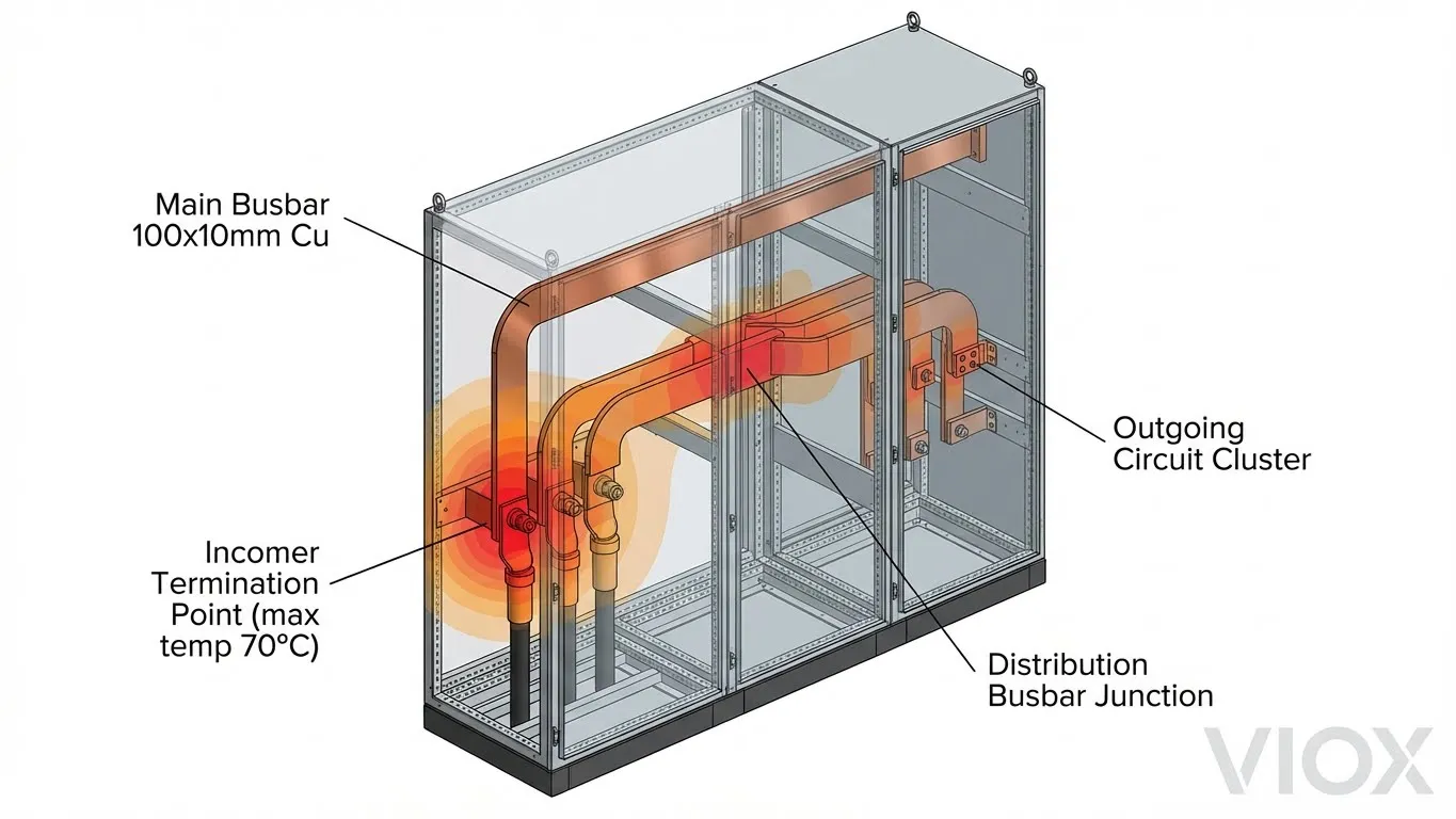
Busbar current capacity isn’t just about copper cross-section. IEC 61439-1 verifies temperature rise at the hottest point in the assembly—typically where:
- Busbars make 90° bends (creates localized eddy currents)
- Incoming cables terminate (resistance at compression lugs)
- Outgoing devices cluster tightly (cumulative heat radiation)
- Ventilation is restricted (internal air circulation patterns)
A 100×10mm copper busbar has a theoretical capacity of ~850A in free air. The same busbar in an IP54 enclosed switchgear with cable glands, surrounded by loaded circuit breakers, mounted vertically in 45°C ambient temperature, may only distribute 500A without violating temperature limits.
Critical Misconception: InA ≠ Main Circuit Breaker Rating. A 630A main breaker doesn’t guarantee InA = 630A. If the busbar layout limits distribution to 500A, then InA = 500A, and the assembly must be derated accordingly.
InA Calculation Example: Dual Incomer Scenario
Consider a typical industrial switchboard with two incoming feeders for supply redundancy:
| Parameter | Incomer 1 | Incomer 2 | Busbar Capacity |
|---|---|---|---|
| Circuit Breaker Rating (In) | 630A | 630A | Rated 1,000A conductor |
| Inc (Incoming Circuit Rating) | 600A | 600A | – |
| Sum of Inc (Parallel Operation) | – | – | 1,200A |
| Busbar Distribution Capacity (verified by temp rise test in this specific enclosure/layout) | – | – | 800A |
| InA (Assembly Rated Current) | – | – | 800A ✓ |
Result: Despite having two 600A incoming circuits (sum = 1,200A), the physical busbar arrangement in this assembly can only distribute 800A. Therefore, InA = 800A. The assembly nameplate must declare this limitation.
Temperature Rise Verification Requirements
IEC 61439-1, Table 8 specifies maximum temperature rise limits (above ambient) for different components:
- Bare busbars (copper): 70K rise (70°C above ambient)
- Bolted busbar connections: 65K rise
- MCB/MCCB terminals: 70K rise
- Cable termination lugs: 70K rise
- Accessible external surfaces (metal): 30K rise
- Handle/grips: 15K rise
These limits assume 35°C ambient. At 45°C ambient, a busbar reaching 115°C (70K rise) is at the absolute limit. Any additional load or compromised ventilation causes failure.
When InA Becomes Mission-Critical
- Solar PV Microgeneration: When rooftop solar feeds back into a distribution board, Regulation 551.7.2 (BS 7671) requires: InA ≥ In + Ig(s) where In = supply fuse rating, Ig(s) = generator rated output current. A 100A supply with 16A solar output needs InA ≥ 116A minimum.
- EV Charging Installations: Multiple 7kW-22kW EV chargers create sustained loads exceeding typical diversity assumptions, demanding verified InA capacity.
- Data Centers: Server loads run at 90-95% capacity 24/7, requiring switchgear with InA = actual connected load (no diversity credit).
VIOX Design Note: Always verify InA matches your load profile. Request manufacturer’s temperature rise test report showing the specific assembly configuration tested—not generic busbar tables.
Inc – Rated Current of a Circuit: Beyond Breaker Nameplates
Definition and Application (IEC 61439-1:2020, Clause 5.3.2)
Inc is the current rating of a specific circuit within the assembly, considering thermal interactions with adjacent circuits and the assembly’s physical arrangement. This is fundamentally different from the device’s nominal rating (In).
An MCB carries a nameplate rating (In)—for example, 63A. This rating is established by testing the breaker in isolation under standard conditions (see IEC 60898-1 specifications). But when that same 63A MCB is mounted in a densely packed switchboard, surrounded by other loaded devices, the circuit rating Inc may be significantly lower—perhaps only 50A continuous.
Device Rating (In) vs. Circuit Rating (Inc)
| Condition | Device Rating (In) | Circuit Rating (Inc) | Derating Factor |
|---|---|---|---|
| Single MCB in open air, 30°C ambient | 63A | 63A | 1.0 |
| Same MCB in enclosed panel, 35°C, with 3 adjacent loaded MCBs | 63A | ~55A | 0.87 |
| Same MCB in tightly packed IP54 enclosure, 40°C, 8 adjacent loaded MCBs | 63A | ~47A | 0.75 |
| Same MCB with cable termination adding 5W loss, poor ventilation | 63A | ~44A | 0.70 |
Key Insight: The device doesn’t change—the 63A MCB is still rated 63A on its own. But the circuit’s ability to dissipate heat in that specific installation determines Inc. This is what IEC 61439 verifies.
Factors Affecting Inc Determination
- Mounting Density: MCBs mounted side-by-side with no spacing conduct heat between adjacent devices. Manufacturers test specific configurations—for example, “10 MCBs in a row, alternating loaded/unloaded” to determine worst-case Inc.
- Cable Termination Losses: Every bolted or clamped connection adds resistance. A poorly torqued lug adds 2-3W of heat per pole at 50A. Multiply across 20 outgoing circuits, and you’ve added 100W+ heat load affecting Inc for all circuits.
- Enclosure Ventilation: IP21 open-bottom enclosures dissipate heat naturally. IP54 gasketed enclosures trap heat. IP65 polycarbonate boxes in direct sunlight create extreme internal temperatures. Inc must account for this.
- Busbar Proximity: Circuits mounted close to high-current busbars (incomer feeds) experience radiant heat from the busbars themselves, reducing their Inc below devices mounted remotely.
- Altitude and Ambient Conditions: See our guide on electrical derating for temperature, altitude, and grouping factors for detailed calculations.
Real-World Example: 63A MCB in a Packed Panel
An industrial control panel contains:
- 12× 63A MCBs for motor feeders
- Mounted in a single DIN rail row
- IP54 enclosure in 40°C ambient (machinery room)
- Poor natural ventilation (no fans)
Manufacturer’s verification: Temperature rise testing shows that with all 12 circuits loaded to 63A simultaneously, terminal temperatures exceed 110°C (40°C ambient + 70K rise limit). To comply with IEC 61439-1, the manufacturer declares:
- Device rating (In): 63A per MCB
- Circuit rating (Inc): 47A per circuit in this configuration
- Required RDF: 0.75 (explained in next section)
Practical Impact: Each motor circuit must be limited to 47A continuous load, or the panel must be reconfigured with spacing/ventilation to achieve higher Inc values.
For comparison with older standards, see our article on IEC 60947-3 utilization categories which governs the devices themselves, not the assembly.
RDF – Rated Diversity Factor: The Critical Thermal Multiplier
Definition and Purpose (IEC 61439-1:2020, Clause 5.3.3)
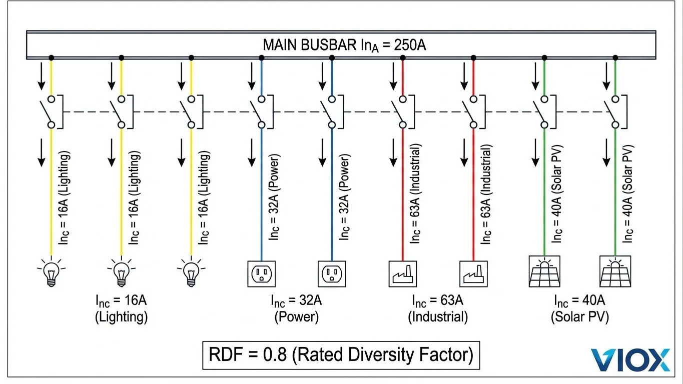
RDF (Rated Diversity Factor) is the per-unit value of Inc to which all outgoing circuits (or a group of circuits) can be continuously and simultaneously loaded, accounting for mutual thermal influences. It is assigned by the assembly manufacturer based on temperature rise verification.
Critical Distinction: RDF is NOT an electrical diversity factor (like those in BS 7671 or NEC Article 220). Those codes estimate actual load usage patterns (“not all loads run simultaneously”). RDF is a thermal derating factor that limits circuit loading to prevent overheating when all circuits do run simultaneously.
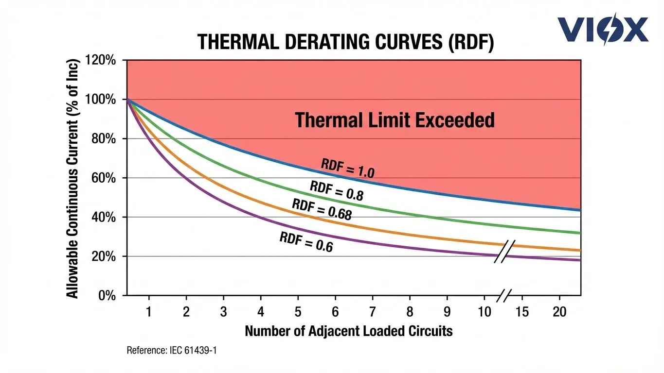
RDF Values and Their Meaning
| RDF Value | Interpretation | Typical Applications |
|---|---|---|
| 1.0 | All circuits can carry full Inc continuously at the same time | Solar PV systems, data centers, industrial process lines with continuous duty, critical infrastructure |
| 0.8 | Each circuit limited to 80% of Inc for continuous simultaneous loading | Commercial buildings with mixed loads, well-ventilated panels, moderate load density |
| 0.68 | Each circuit limited to 68% of Inc for continuous simultaneous loading | Residential distribution boards, tightly packed enclosures, high ambient temperatures |
| 0.6 | Each circuit limited to 60% of Inc for continuous simultaneous loading | Extremely dense panels, poor ventilation, elevated ambient conditions, retrofit scenarios |
Example: A distribution board has an outgoing circuit with Inc = 50A and RDF = 0.68. The maximum continuous simultaneous load allowed for that circuit is:
IB (operating current) = Inc × RDF = 50A × 0.68 = 34A
If you need to load that circuit to 45A continuously, you have two options:
- Specify a panel with higher RDF (e.g., 0.9 → 50A × 0.9 = 45A ✓)
- Request a configuration where that circuit has higher Inc rating (e.g., Inc = 63A → 63A × 0.68 = 43A, still insufficient; need Inc = 67A or RDF = 0.9)
How Manufacturers Determine RDF Through Testing
IEC 61439-1 Clause 10.10 requires temperature rise verification by:
Method 1 – Full Testing: Load the assembly to rated conditions (InA at incomers, outgoing circuits at Inc × RDF) for sufficient time to reach thermal equilibrium. Measure temperatures at critical points. If all stay below limits (Table 8), the RDF is validated.
Method 2 – Calculation (allowed up to InA ≤ 1,600A): Use thermal modeling per IEC 61439-1 Annex D, accounting for:
- Power dissipation of each component (from manufacturer data)
- Heat transfer coefficients (convection, radiation, conduction)
- Enclosure thermal properties (material, surface area, ventilation openings)
Method 3 – Proven Design: Demonstrate the assembly is derived from a previously tested similar design with documented modifications that don’t worsen thermal performance.
Most manufacturers use Method 1 for flagship product lines, then derive variants using Method 3. Custom panels often require Method 2 calculations.
RDF Application Example: 8-Circuit Distribution Board
A commercial building distribution board contains:
| Circuit | Device (In) | Inc Rating | RDF | Max Continuous Load (IB) | Actual Load |
|---|---|---|---|---|---|
| Incomer | 100A MCCB | 100A | – | – | Sum of outgoing |
| Circuit 1 | 32A MCB | 32A | 0.7 | 22.4A | 20A (Lighting) |
| Circuit 2 | 32A MCB | 32A | 0.7 | 22.4A | 18A (Lighting) |
| Circuit 3 | 40A RCBO | 40A | 0.7 | 28A | 25A (HVAC) |
| Circuit 4 | 40A RCBO | 40A | 0.7 | 28A | 27A (HVAC) |
| Circuit 5 | 20A MCB | 20A | 0.7 | 14A | 12A (Receptacles) |
| Circuit 6 | 20A MCB | 20A | 0.7 | 14A | 11A (Receptacles) |
| Circuit 7 | 63A MCB | 50A* | 0.7 | 35A | 32A (Kitchen) |
| Circuit 8 | 63A MCB | 50A* | 0.7 | 35A | 30A (Kitchen) |
*Circuit 7 & 8 have Inc < In due to mounting position near heat source
Verification: Total actual load = 175A. With RDF = 0.7, the board can handle sum of (Inc × RDF) = 199.2A maximum. The board is adequately rated, but if Circuit 7 or 8 need to run at full 63A, you’d exceed thermal limits (63A > 35A allowed).
Critical Applications Requiring RDF = 1.0
- Solar PV Combiner Boxes: PV arrays produce maximum power for 4-6 hours daily during peak sun. String currents flow at rated capacity simultaneously. Any RDF < 1.0 causes nuisance overcurrent trips or long-term busbar degradation. See our solar combiner box design guide.
- Data Centers and Server Rooms: IT loads operate 24/7 at 90-95% of rated capacity. Even brief thermal excursions risk equipment damage. RDF must equal 1.0, and thermal calculations should include worst-case scenarios.
- Industrial Continuous Processes: Chemical plants, water treatment, 24-hour manufacturing—any process where stopping = expensive downtime requires RDF = 1.0 rated switchgear.
- EV Charging Stations: Multiple Level 2 chargers running simultaneously for hours demand full thermal capacity. Typical RDF = 0.7 consumer boards fail rapidly in these applications.
Common Mistakes Engineers Make with RDF
Mistake 1: Confusing RDF with electrical diversity/demand factors from NEC or BS 7671. These are not the same. Electrical diversity reduces total connected load based on usage patterns (not all loads run simultaneously). RDF limits individual circuit loading even when all loads do run simultaneously due to thermal constraints.
Mistake 2: Applying RDF to short-duration loads. IEC 61439-1 defines “continuous” as loads operating >30 minutes. For short-duty cycles (e.g., motor starting, inrush currents), RDF typically doesn’t apply—thermal mass prevents temperature rise in brief events.
Mistake 3: Assuming RDF applies equally to all circuits. Manufacturers may assign different RDF values to different sections or groups within an assembly. Always check the specific circuit’s RDF value.
Mistake 4: Ignoring RDF during panel modifications. Adding circuits to an existing board changes thermal loading. If the original RDF was 0.8 based on “5 circuits loaded,” adding 3 more loaded circuits may reduce effective RDF to 0.65 unless ventilation is improved.
For related protective device sizing considerations, consult our guide on circuit breaker ratings: ICU, ICS, ICW, ICM.
The Interrelationship: How InA, Inc, and RDF Work Together
The Fundamental Verification Equation
A compliant IEC 61439 assembly must satisfy:
Σ (Inc × RDF) ≤ InA
Where:
- Σ (Inc × RDF) = sum of all outgoing circuit loadings (adjusted for simultaneous operation)
- InA = assembly rated current (busbar distribution capacity)
This equation ensures that the total thermal load on the assembly, accounting for continuous simultaneous operation of all circuits at their thermally derated capacity, doesn’t exceed what the busbar system can distribute without overheating.
Design Verification Sequence
- Determine Load Requirements: Calculate actual operating currents (IB) for all circuits
- Select Circuit Protection Devices: Choose MCBs/RCBOs with In ≥ IB (standard overcurrent protection sizing)
- Verify Assembly Configuration: Manufacturer determines Inc for each circuit based on physical layout
- Apply RDF: Manufacturer assigns RDF based on temperature rise verification
- Check Compliance: For each circuit, verify IB ≤ (Inc × RDF)
- Verify InA Capacity: Ensure Σ(Inc × RDF) ≤ InA
If Step 5 or 6 fails, options are:
- Increase panel size/ventilation to improve RDF
- Reduce circuit loading (IB)
- Reconfigure layout to increase Inc
- Upgrade busbars to increase InA
Case Study: Mixed-Load Facility Distribution Board
Scenario: Industrial facility with office area, production floor, and rooftop solar PV. Single main distribution board.
| Circuit | Load Type | IB (A) | Device In (A) | Inc (A) | RDF | Inc×RDF (A) | Compliant? |
|---|---|---|---|---|---|---|---|
| Incomer | Utility supply | – | 250A MCCB | 250A | – | – | – |
| C1 | Office HVAC | 32 | 40A MCB | 40A | 0.8 | 32A | ✓ (32A ≤ 32A) |
| C2 | Office lighting | 18 | 25A MCB | 25A | 0.8 | 20A | ✓ (18A ≤ 20A) |
| C3 | Office receptacles | 22 | 32A MCB | 32A | 0.8 | 25.6A | ✓ (22A ≤ 25.6A) |
| C4 | Production Line 1 | 48 | 63A MCB | 55A* | 0.8 | 44A | ❌ (48A > 44A) |
| C5 | Production Line 2 | 45 | 63A MCB | 55A* | 0.8 | 44A | ✓ (45A ≤ 44A) |
| C6 | Welding equipment | 38 | 50A MCB | 50A | 0.8 | 40A | ✓ (38A ≤ 40A) |
| C7 | Compressor | 52 | 63A MCB | 60A | 0.8 | 48A | ❌ (52A > 48A) |
| C8 | Solar PV backfeed | 20 | 25A MCB | 25A | 1.0 | 25A | ✓ (20A ≤ 25A) |
*Inc reduced due to mounting position in high-density section
Analysis:
- InA declared: 250A (limited by busbar distribution in this configuration)
- Σ(Inc × RDF): 32 + 20 + 25.6 + 44 + 44 + 40 + 48 + 25 = 278.6A → Exceeds InA!
Problems:
- Circuit C4 exceeds its thermal limit (48A load > 44A allowed)
- Circuit C7 exceeds its thermal limit (52A load > 48A allowed)
- Total thermal loading (278.6A) exceeds assembly capacity (250A InA)
Solutions:
- Reconfigure C4 & C7: Move these high-load circuits to a section with better ventilation, increasing their Inc to 63A and 65A respectively → Inc×RDF becomes 50.4A and 52A ✓
- Upgrade InA: Install larger busbar or improve cooling to achieve InA = 300A (requires new thermal calculation)
- Split Distribution: Use a sub-distribution board for production loads, reducing main board loading
- Verify Solar PV Requirement: Note C8 has RDF = 1.0 (cannot be thermally derated) because solar generates continuously during daylight. See BS 7671 Regulation 551.7.2 and our microgeneration installation guide for requirements.
Future Expansion Considerations
Warning: A board operating at 90% of InA today has no thermal margin for expansion. When specifying new installations:
- Specify InA at 125-150% of initial load for 10-year expansion capability
- Request manufacturer document spare circuit capacity (how many additional circuits before RDF degrades)
- For critical facilities, request thermal modeling report showing temperature margins
VIOX Best Practice: We design switchgear with InA rated for actual connected load plus 30% margin, and verify RDF for worst-case simultaneous loading. All thermal calculations and test reports are provided with delivery documentation, ensuring installers have complete information for future modifications.
Practical Application Guide for Specifying IEC 61439 Switchgear
Step-by-Step Specification Checklist
Phase 1: Load Analysis
- Calculate design current (IB) for each circuit using actual load data
- Identify continuous loads (operate >30 min) vs. short-duration loads
- Determine ambient temperature at installation site (critical for derating)
- Assess ventilation conditions (natural, forced, restricted)
- Document future expansion requirements
Phase 2: Initial Equipment Selection
- Select overcurrent protective devices with In ≥ IB
- Choose assembly type: PSC (IEC 61439-2) for industrial, or DBO (IEC 61439-3) for ordinary person operation
- Specify required InA based on: max(sum of incoming circuits, Σ(IB with diversity))
- Consider switchboard vs. switchgear distinctions
Phase 3: Verification Requirements
- Request manufacturer provide Inc ratings for each circuit in the proposed configuration
- Request declared RDF value(s) for the assembly or circuit groups
- Verify: IB ≤ (Inc × RDF) for all continuous-duty circuits
- Verify: Σ(Inc × RDF) ≤ InA for the complete assembly
- Request temperature rise test report or calculation (IEC 61439-1, Clause 10.10)
Phase 4: Documentation Review
- Confirm nameplate markings include InA, Inc schedule, and RDF
- Review design verification documents (test reports, calculations, or proven design references)
- Check compliance with applicable parts of IEC 61439 series (part 1, 2, or 3)
- Verify altitude/temperature correction factors applied if needed (see derating guide)
Reading Manufacturer Datasheets Correctly
What to Look For:
- InA Declaration: Must be clearly stated, not buried in fine print. Beware datasheets showing only “busbar rating” without assembly InA.
- Inc Schedule: Professional manufacturers provide a circuit-by-circuit Inc table, not just generic device ratings. If the datasheet only lists “10× 63A MCB,” demand actual Inc values for those specific positions.
- RDF Value and Applicability: Should state RDF and clarify if it applies to all circuits, specific groups, or sections. Statements like “RDF = 0.8 for standard loading” are vague—demand specifics.
- Temperature Rise Verification: Request reference to test report number or calculation file. Per IEC 61439-1, this documentation must exist.
- Ambient Temperature Rating: Standard is 35°C. If your site exceeds this, derating is required. Ask for 40°C or 45°C rated assemblies (reduces InA/Inc by ~10-15%).
Red Flags in Specifications
🚩 Datasheet shows InA = main breaker In: Suggests the assembly hasn’t been properly verified. InA should be determined by thermal analysis, not simply copied from the incomer breaker rating.
🚩 No RDF stated, or “RDF = 1.0” without justification: Either incomplete documentation, or the manufacturer hasn’t performed verification. Request test reports.
🚩 Generic Inc values without reference to assembly configuration: Inc depends on physical layout. A datasheet stating “63A MCB = Inc 63A” for all positions in all panel sizes is non-compliant.
🚩 “Based on IEC 60439” or “Meets legacy standards”: IEC 60439 has been superseded. Equipment must comply with IEC 61439 series (transition period ended 2014).
🚩 No temperature rise documentation available: Per Clause 10.10, verification is mandatory. If the manufacturer can’t provide this, the assembly is not compliant.
When to Request Thermal Calculations
Always request thermal calculations when:
- Custom panel layout deviates from manufacturer’s standard designs
- Ambient temperature exceeds 35°C
- Enclosure has restricted ventilation (IP54+, sealed environments)
- High-density circuit loading (>60% of available spaces populated)
- Continuous-duty applications (data centers, process industries, solar PV)
- Altitude >1,000m (reduced cooling efficiency)
IEC 61439 Documentation Requirements
Compliant assemblies must include:
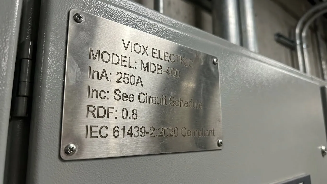
- Nameplate (IEC 61439-1, Clause 11.1):
- Manufacturer name/trademark
- Type designation or identification
- IEC 61439-X compliance (relevant part)
- InA (assembly rated current)
- Rated voltage (Ue)
- Rated frequency
- Degree of protection (IP rating)
- Conditional short-circuit current (if applicable)
- Technical Documentation (IEC 61439-1, Clause 11.2):
- Single-line diagram
- Circuit identification schedule with Inc ratings
- RDF declaration
- Temperature rise verification report or reference
- Short-circuit verification
- Maintenance and operation instructions
- Verification Records: For design verification by testing, calculations, or proven design, formal records must be retained and available for inspection.
Common Specification Errors and Fixes
| Error | Consequence | Correct Approach |
|---|---|---|
| Specifying “400A panel” without stating InA, Inc, or RDF | Manufacturer delivers cheapest compliant solution; may have InA = 320A with RDF = 0.7 | Specify: “InA ≥ 400A, RDF ≥ 0.8 for all outgoing circuits, Inc schedule per load list” |
| Using device ratings (In) for load calculations | Overloading—actual Inc may be lower | Request Inc schedule, verify IB ≤ (Inc × RDF) |
| Ignoring ambient conditions | Field overheating in summer or high-temp environments | Specify ambient temp, request derating factors |
| Adding circuits post-delivery without re-verification | Thermal overload, warranty void | Engage manufacturer for modification verification |
| Assuming RDF from one panel applies to another | Different layouts have different RDF values | Request RDF specific to your configuration |
VIOX Technical Support: Our engineering team provides pre-sale thermal analysis for custom projects. Submit load schedules and installation conditions, and we’ll deliver Inc/RDF verification before you commit to purchase. For standard products, comprehensive test reports are included with shipment.
Conclusion: Three Numbers That Define Real-World Capacity
The difference between a switchgear assembly that performs reliably for 20 years and one that fails within months often comes down to understanding InA, Inc, and RDF. These three interconnected parameters—mandated by IEC 61439 but still widely misunderstood—define the thermal reality of continuous-duty power distribution.
Key Takeaways:
- InA is the assembly’s total distribution capacity, limited by busbar thermal performance in that specific physical arrangement—not the main breaker rating
- Inc is the current rating of each circuit considering mounting position, adjacent heat sources, and thermal interactions—not the device nameplate rating
- RDF is the thermal derating factor for continuous simultaneous loading—not an electrical diversity factor from installation codes
When specifying or purchasing switchgear, demand these three values with supporting documentation. Verify the fundamental equation: Σ(Inc × RDF) ≤ InA. Request temperature rise test reports or calculations. Don’t accept vague datasheets or unverified claims.
Understanding InA, Inc, and RDF prevents:
- Field failures from thermal overload
- Costly retrofits when loads don’t match expectations
- Non-compliance with IEC 61439 during inspections
- Warranty disputes over “inadequate rating”
- Production downtime from nuisance trips
VIOX Commitment: Every VIOX switchgear assembly ships with complete IEC 61439 compliance documentation—InA nameplate markings, Inc circuit schedules, declared RDF values, and temperature rise verification records. Our engineers work with you during specification to ensure thermal margins match your application, not just meet minimum standards.
As power systems evolve toward higher utilization factors (solar PV, EV charging, always-on data infrastructure), thermal management becomes increasingly critical. The future includes smart monitoring—digital twins that predict thermal margins in real-time, alerting operators before problems occur. But the foundation remains these three fundamental ratings: InA, Inc, and RDF.
Specify them clearly. Verify them thoroughly. Your electrical infrastructure depends on it.
Frequently Asked Questions (FAQ)
What happens if I exceed the InA rating?
Exceeding InA causes the main busbars to operate above their temperature rise limits (typically 70K above ambient). In the short term, this accelerates insulation aging, loosens bolted connections due to thermal expansion cycles, and increases contact resistance. Long-term consequences include busbar oxidation, charred insulation, and eventual flashover or fire. Most critically, overcurrent protection devices may not trip—a 250A main breaker doesn’t protect against thermal overload at 260A continuous load. The assembly is designed as a system; exceeding InA compromises the entire thermal balance.
Can I use a circuit at full Inc if RDF < 1.0?
No. RDF specifically limits continuous simultaneous loading to Inc × RDF. If Inc = 50A and RDF = 0.7, the maximum continuous load allowed is 35A. Operating at 50A violates IEC 61439 temperature limits even though the circuit breaker hasn’t tripped. Short-duration loads (< 30 minutes on-time with adequate off-time cooling) may approach full Inc, but continuous duty must respect RDF. If your application requires full Inc continuous loading, specify an assembly with RDF = 1.0 or request a configuration with higher Inc for that specific circuit.
How do I determine RDF for my specific panel configuration?
RDF must be provided by the assembly manufacturer, not calculated by the installer or designer. It’s determined through:
- Temperature rise testing per IEC 61439-1, Clause 10.10
- Thermal calculation using validated models (Annex D)
- Derivation from a proven design with documented similarity
When requesting quotes, specify: “Provide declared RDF value with supporting test report or calculation reference.” If the manufacturer cannot provide RDF documentation, the assembly is not IEC 61439 compliant. For custom panels deviating from standard catalog designs, request formal thermal analysis—VIOX provides this service at the specification stage for projects above 100A InA.
Does RDF apply to short-term loads (< 30 minutes)?
Generally no. RDF addresses thermal equilibrium under continuous loading (>30 minutes where temperature stabilizes). Short-duration loads like motor starting, welding bursts, or brief overloads benefit from thermal mass—the assembly doesn’t reach steady-state temperature. However, if short-duration loads cycle rapidly (e.g., 20 min ON / 10 min OFF repeatedly), the assembly never fully cools, and RDF effectively applies. For duty-cycle applications, consult the manufacturer with your specific loading profile. IEC 61439-1 doesn’t prescribe exact duty cycle rules—thermal verification determines limits.
What’s the difference between RDF and diversity factors in electrical codes (BS 7671, NEC)?
Electrical diversity factors (BS 7671 Appendix A, NEC Article 220) estimate actual load usage: “Not all circuits operate simultaneously.” They reduce total connected load for sizing supply cables and transformers based on statistical usage patterns. Example: Five 30A residential kitchen circuits might have a diversity factor of 0.4, assuming only 40% average usage.
RDF (Rated Diversity Factor) is a thermal limit for continuous operation: “Even if all circuits do run simultaneously, heat buildup limits each circuit to Inc × RDF.” It’s a physical constraint, not a statistical estimate. You can apply electrical diversity to reduce supply sizing, but you cannot exceed thermal limits defined by RDF.
Example confusion: An engineer applies 0.7 diversity to reduce supply sizing (correct), then assumes each circuit can run at 100% Inc because “loads won’t all run together” (incorrect). Even if loads don’t statistically all run together, when they do, each must stay within Inc × RDF thermal limits.
Can InA be higher than the main circuit breaker rating?
Yes, InA can exceed the main breaker In rating. InA is determined by busbar thermal capacity in a specific layout, while the main breaker In is selected for overcurrent/short-circuit protection based on supply characteristics and coordination.
Example: A switchboard has InA = 800A (verified by busbar thermal testing). The supply transformer fault level and coordination requirements dictate a 630A main breaker (In = 630A). The assembly can distribute 800A thermally, but the overcurrent protection limits supply to 630A. This is compliant.
Conversely, InA can be lower than main breaker rating—more common scenario causing field confusion. A 400A main breaker doesn’t guarantee InA = 400A if busbar layout limits distribution to 320A.
How does ambient temperature affect these ratings?
IEC 61439-1 standard ratings assume 35°C ambient (per Table 8). Operation at higher temperatures reduces current capacity because components start closer to temperature limits. Typical derating:
- 40°C ambient: Reduce InA/Inc by ~10%
- 45°C ambient: Reduce by ~15-20%
- 50°C ambient: Reduce by ~25-30%
These are approximations—exact derating depends on assembly design. Always request manufacturer’s temperature correction curves. For installations above 40°C ambient (machinery rooms, tropical climates, outdoor enclosures in sun), specify this upfront. VIOX can provide assemblies rated for elevated ambient temperatures, or apply correction factors to standard designs.
Altitude also affects cooling (reduced air density). Above 1,000m, additional derating applies—see our comprehensive derating guide for detailed calculations.
