
Understanding Single-Phase vs. Three-Phase Power Systems
Single-Phase Systems (1P+N): 220-240V Applications
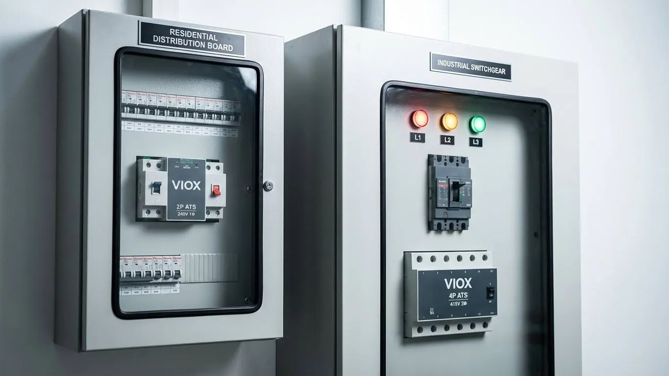
Single-phase power systems operate at 220-240V and consist of one hot conductor (L1) and one neutral conductor (N). These systems typically require a 2-pole (2P) automatic transfer switch that switches both the hot conductor and neutral simultaneously.
Primary Applications:
- Residential buildings and apartments
- Small commercial offices (under 100A service)
- Recreational vehicles (RVs) and mobile homes
- Light-duty equipment and appliances
- Backup power for home essential loads
Single-phase systems are limited in their power delivery capacity, typically maxing out at 100A service (24kW at 240V). For residential backup power applications, a 2P ATS provides adequate protection when switching between utility and generator sources.
Three-Phase Systems (3P+N): 380-415V Industrial Power
Three-phase power systems deliver 380-415V through three hot conductors (L1, L2, L3) plus a neutral conductor (N). These systems require either a 3-pole (3P) or 4-pole (4P) automatic transfer switch, depending on whether the neutral needs to be switched—a critical decision that affects system safety and reliability.
Primary Applications:
- Manufacturing facilities and industrial plants
- Commercial buildings with HVAC systems
- Data centers and telecommunications facilities
- Facilities operating three-phase motors (pumps, compressors, chillers)
- Large-scale solar PV installations with hybrid inverter systems
| System Type | Voltage | Conductors | Typical ATS | Max Load Capacity | Common Applications |
|---|---|---|---|---|---|
| Single-Phase | 220-240V | L1 + N | 2P | Up to 24kW | Residential, small commercial |
| Three-Phase | 380-415V | L1 + L2 + L3 + N | 3P or 4P | Up to 400kW+ | Industrial, large commercial |
| Split-Phase | 120/240V | L1 + L2 + N | 3P (special) | Up to 48kW | North American residential |
The “4th Pole” Dilemma: 3P vs. 4P ATS Selection
This is where most specification errors occur. The decision between a 3-pole and 4-pole ATS fundamentally changes how your system handles neutral grounding and fault protection.
3-Pole ATS: Switched Phases, Solid Neutral
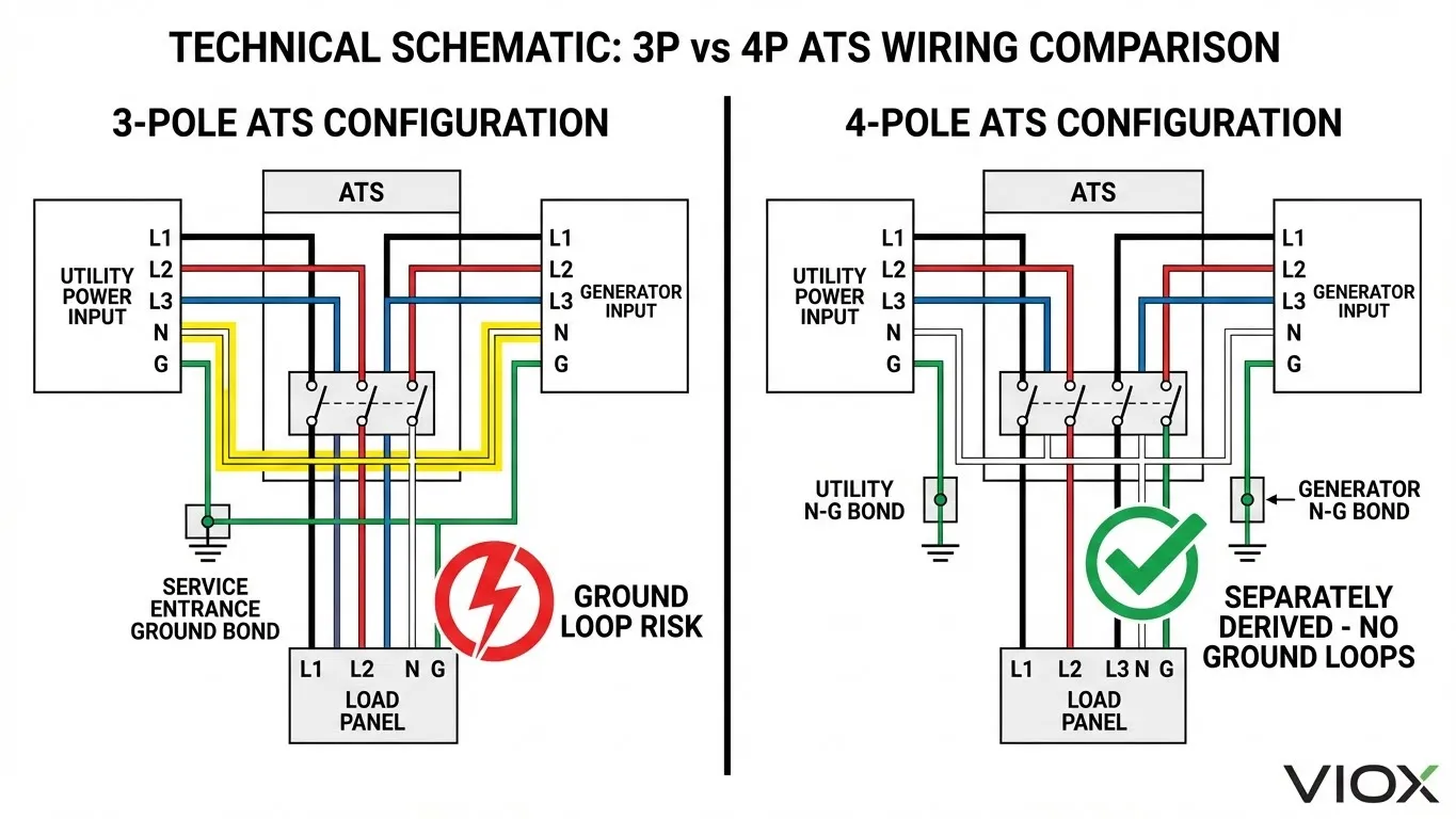
A 3P ATS switches only the three hot conductors (L1, L2, L3) while leaving the neutral conductor as a solid pass-through connection between both power sources.
Configuration:
- Switches: L1, L2, L3
- Pass-through: Neutral (N)
- Grounding: Single bonding point at service entrance
- Generator: Neutral NOT bonded to ground (floating neutral)
Critical Limitation:
When using a 3P ATS, the generator’s neutral must not be bonded to ground at the generator. All neutral-to-ground bonding occurs only at the utility service entrance. This creates a non-separately derived system where the generator shares the utility’s grounding reference.
Risks of 3P ATS with Solid Neutral:
- Ground Loop Formation: When both utility and generator neutrals connect through the solid neutral bus, any voltage potential difference between the two grounding systems creates circulating currents. This is especially problematic in hybrid solar-battery systems where the inverter may introduce DC offset currents.
- RCD/GFCI Incompatibility: Residual current circuit breakers (RCCBs) measure current imbalance between phase and neutral conductors. With a solid neutral, fault currents can return through alternate paths, causing nuisance tripping or—worse—failure to trip during actual ground faults.
- Neutral Potential Differences: If the generator and utility have different grounding impedances (common in mobile generators or temporary installations), the neutral can float to dangerous voltages when the de-energized source is still connected through the neutral bus.
- Ground Fault Relay Conflicts: Systems with ground fault protection on both sources will see false ground fault currents flowing through the de-energized source’s neutral path, potentially tripping protective devices unnecessarily.
4-Pole ATS: Complete Source Isolation
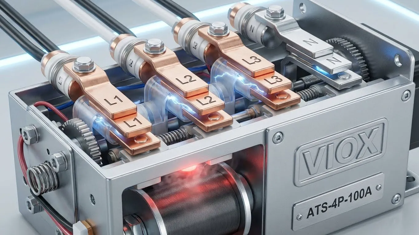
A 4P ATS switches all four conductors: L1, L2, L3, and neutral. This creates electrically isolated, separately derived systems.
Configuration:
- Switches: L1, L2, L3, N
- Pass-through: None (complete isolation)
- Grounding: Separate bonding at each source
- Generator: Neutral bonded to ground at generator
Advantages of 4-Pole Configuration:
- Separately Derived System Compliance: Each power source (utility, generator, solar inverter) becomes an independent separately derived system with its own neutral-ground bond. This meets NEC Article 250.30 requirements and eliminates parallel ground paths.
- Ground Loop Prevention: By completely disconnecting the inactive source, no circulating currents can flow between different grounding systems. This is critical in solar hybrid systems where inverter-based sources may introduce harmonics or DC components.
- RCD Protection Compatibility: Ground fault protection devices work correctly because each source’s protection sees only its own fault currents, with no interference from the alternate source’s ground path.
- Voltage Reference Stability: Each source establishes its own stable neutral reference, eliminating voltage fluctuations caused by neutral potential differences between sources.
VIOX Engineering Recommendation
For hybrid solar-battery systems, generator backup installations, and any application using multiple power sources, VIOX strongly recommends 4-pole automatic transfer switches.
The marginal cost increase (typically 15-25% over 3P units) is insignificant compared to the elimination of ground loop issues, nuisance RCD tripping, and potential equipment damage from neutral voltage imbalances. In our field testing with over 2,000 solar combiner box installations, systems using 4P ATS configurations showed 92% fewer grounding-related service calls compared to 3P configurations.
| Feature | 3-Pole ATS | 4-Pole ATS |
|---|---|---|
| Phases Switched | L1, L2, L3 | L1, L2, L3, N |
| Neutral Handling | Solid pass-through | Switched (isolated) |
| Generator N-G Bond | Must be removed | Required at generator |
| System Type | Non-separately derived | Separately derived |
| Ground Loops | High risk | Eliminated |
| RCD Compatibility | Limited | Full compatibility |
| Hybrid Solar | Not recommended | Recommended |
| Cost Premium | Base price | +15-25% |
| NEC Compliance | Requires careful design | Automatic compliance |
Split-Phase Systems: The North American Selection Trap
Split-phase power, common in the United States, Philippines, and Taiwan, presents a unique challenge that trips up many engineers specifying transfer switches.
What is Split-Phase Power?
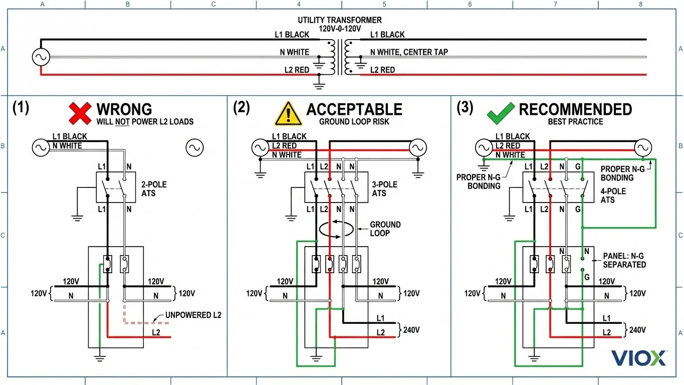
Split-phase delivers 120V/240V through a center-tapped transformer secondary winding:
- L1 to Neutral: 120V
- L2 to Neutral: 120V
- L1 to L2: 240V
Despite being called “single-phase,” split-phase systems have two hot conductors (L1, L2) that are 180° out of phase, plus a neutral conductor.
The ATS Selection Trap
Common Error: Specifying a standard 2-pole ATS for split-phase systems.
Problem: A standard 2P ATS designed for true single-phase systems (one hot + neutral) cannot properly handle split-phase systems with two hots. You need to switch both L1 and L2, not just one.
Correct Solutions:
- Three-Pole ATS Configuration: Use a 3P ATS to switch L1, L2, and neutral. This treats the split-phase system like a three-phase system with only two phases used.
- Special Split-Phase 2P ATS: Some manufacturers offer specialized 2P switches that switch both L1 and L2 simultaneously while leaving neutral as pass-through. However, these still suffer from the ground loop issues discussed above.
Split-Phase Application Requirements
For North American residential backup power systems (typical 200A service):
Recommended: 3-pole ATS with neutral switching or 4-pole ATS (if treating as L1+L2+N+spare)
This configuration:
- Switches both hot legs (L1, L2) independently
- Can optionally switch neutral (recommended for generator systems)
- Allows proper operation of both 120V (L1 or L2 to N) and 240V (L1 to L2) loads
- Prevents backfeed between utility and generator neutrals
Critical Wiring Note: When connecting split-phase to a 3P or 4P ATS:
- L1 → ATS Terminal 1
- L2 → ATS Terminal 2
- Terminal 3 → Leave empty or use for neutral switching
- N → Dedicated neutral terminal (if 4P) or solid bus (if 3P)
This is particularly important for EV charger installations which often require 240V split-phase power for Level 2 charging.
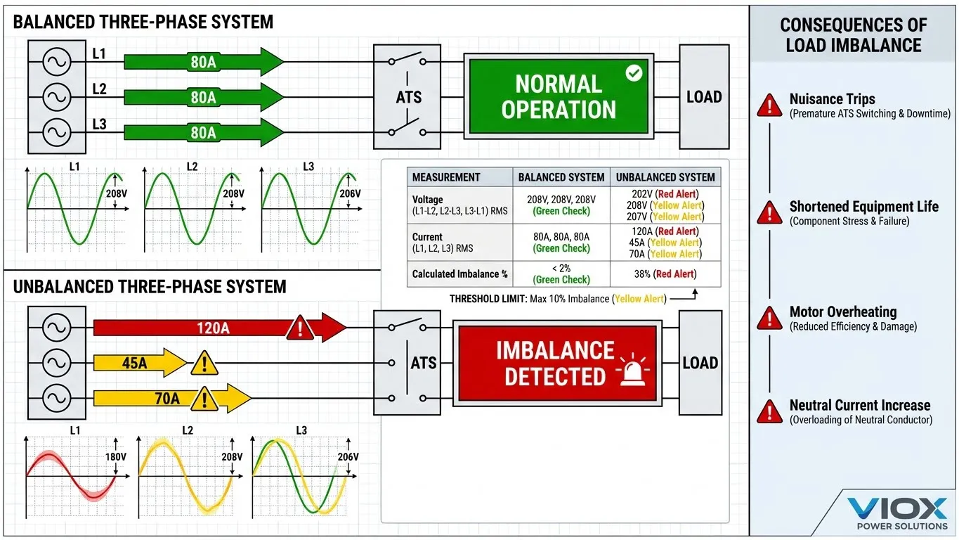
Load Balancing and Phase Voltage Stability
Unbalanced loading in three-phase systems creates operational problems that directly affect ATS performance and reliability.
The Physics of Three-Phase Imbalance
In a perfectly balanced three-phase system, each phase carries equal current (±10%) and the neutral carries minimal current (primarily harmonics). However, real-world installations rarely achieve this balance due to:
- Single-Phase Load Distribution: Most commercial and residential loads are single-phase (lighting, office equipment, computers). When these loads concentrate on one or two phases, significant imbalance occurs.
- Motor Inrush Currents: Three-phase motors and contactors draw high inrush currents during startup. If the system is already unbalanced, this transient event can trigger ATS phase loss or voltage imbalance protection.
- Solar Inverter Output: Hybrid inverters in three-phase systems may produce slightly unbalanced output, especially when battery charging and inverting simultaneously occur.
How Imbalance Affects ATS Operation
Modern automatic transfer switches monitor voltage magnitude and phase angle on all conductors. Typical ATS voltage imbalance trip settings:
- Phase-to-Phase Voltage Imbalance: ±10% from average
- Phase Loss Detection: Any phase drops below 85% nominal
- Neutral Shift Detection: Neutral voltage exceeds 10% phase voltage
Real-World Failure Scenario:
A 415V three-phase system with poor load balance:
- L1: 95A (near capacity)
- L2: 45A (light load)
- L3: 60A (moderate load)
When the facility starts a large three-phase motor (e.g., HVAC compressor), L1 voltage sags to 380V while L2 and L3 remain at 410V. The ATS controller interprets this 7.3% imbalance as a potential phase loss and may unnecessarily transfer to generator, disrupting operations.
Preventing Imbalance-Related ATS Trips
Engineering Solutions:
- Load Distribution Analysis: During initial installation, measure current on each phase during peak operations. Redistribute single-phase loads to achieve ±15% balance across L1, L2, L3.
- Motor Soft Starters: Install soft start controllers on large three-phase motors to reduce inrush current and voltage sag during startup.
- Increased Voltage Imbalance Tolerance: If your ATS allows field adjustment of trip settings, increase voltage imbalance tolerance from 10% to 15% (only if supply quality permits). Consult VIOX technical support before modifying factory settings.
- Phase Balancing Panels: For facilities with predominantly single-phase loads, install automatic phase balancing distribution panels that rotate loads across phases dynamically.
- Generator Sizing: Ensure backup generator capacity exceeds total load by at least 25% to maintain voltage stability during imbalanced loading. An undersized generator will amplify voltage imbalance problems.
If your ATS experiences frequent nuisance transfers due to voltage imbalance, refer to our comprehensive ATS troubleshooting guide which covers voltage monitoring, relay settings, and CT ratio verification procedures.
Additional System Design Considerations
When integrating an ATS into a new or existing electrical distribution system, consider these related components:
- Circuit Breaker Coordination: Ensure upstream and downstream protective devices coordinate properly during ATS transfer operations
- Surge Protection: Install Type 2 SPDs on both utility and generator sides of the ATS to protect against switching transients
- Proper Grounding: Verify grounding electrode systems meet code requirements for separately derived systems
- Distribution Panel Selection: Match panel specifications to ATS output ratings and pole configuration
Quick Reference: ATS Selection Matrix
| Application | Voltage System | Load Type | Recommended ATS | Critical Consideration |
|---|---|---|---|---|
| Residential backup | 240V single-phase | Mixed household | 2P (100-200A) | Standard 2-pole adequate |
| RV/Mobile systems | 120/240V split-phase | Mixed 120V+240V | 3P or 4P (30-50A) | Must switch both hot legs |
| Small commercial | 240V single-phase | Office + HVAC | 2P (200-400A) | Size for inrush current |
| Light industrial | 415V three-phase | Mostly motors | 3P (100-400A) | Check neutral bond location |
| Hybrid solar | 415V three-phase | Inverter + grid | 4P (63-250A) | Prevents ground loops |
| Generator backup | 400V three-phase | Critical loads | 4P (100-630A) | Required for separately derived |
| Data center | 400V three-phase | UPS systems | 4P (400-1000A) | Fast transfer, bypass capability |
| Manufacturing | 415V three-phase | Heavy machinery | 4P (250-800A) | Load balancing critical |
FAQ: Common ATS Pole Configuration Questions
Q: Can I use a 3-pole ATS with a 4-wire three-phase system?
Yes, but only if you maintain a solid neutral connection and ensure the generator neutral is NOT bonded to ground. The generator must operate as a non-separately derived system. However, for hybrid solar systems and installations with RCD protection, VIOX recommends 4-pole configurations to avoid ground loops and nuisance tripping.
Q: Why does my split-phase system need a 3-pole transfer switch?
Split-phase 120/240V systems have two hot conductors (L1, L2) that must both be switched to properly serve 240V loads and maintain balanced 120V circuits. A standard 2-pole switch only switches one hot leg, leaving half your 120V circuits and all 240V loads unpowered during transfer. Use a 3P ATS configured for split-phase, or preferably a 4P ATS with neutral switching.
Q: What happens if I bond the generator neutral in a 3-pole ATS system?
You create a dangerous parallel ground path. When both utility and generator neutrals are bonded to ground and connected through the solid neutral bus, ground fault currents can return through either path. This violates NEC 250.20 requirements, causes ground fault protective devices to malfunction, and creates circulating currents between different grounding electrodes. Always remove generator neutral-ground bonds when using a 3P ATS.
Q: How do I determine if my system is unbalanced enough to cause ATS problems?
Measure phase currents during normal operation with a clamp meter. Calculate the imbalance using this formula:
Imbalance % = (Max Deviation from Average / Average Current) × 100
If imbalance exceeds 20%, redistribute single-phase loads across phases or adjust ATS voltage imbalance trip settings (if allowed). Refer to our ATS troubleshooting guide for detailed measurement procedures.
Q: Can I retrofit a 3-pole ATS to 4-pole configuration?
No. The mechanical construction and contact arrangement are fundamentally different. A 3-pole ATS has three switching contacts plus a solid neutral bus bar. A 4-pole ATS has four independent switching contacts. Upgrading requires complete ATS replacement. VIOX offers retrofit services with minimal downtime for critical applications—contact technical support for site assessment.
Q: Do I need different circuit breakers for 3P vs. 4P ATS systems?
Upstream and downstream circuit breakers should match the ATS pole configuration. For 3P ATS systems, use 3-pole MCCBs or ACBs. For 4P ATS systems, use 4-pole breakers to maintain complete source isolation. This is especially critical in solar installations where DC and AC systems must remain isolated.
VIOX Electric has supplied over 15,000 automatic transfer switches to industrial and commercial customers worldwide since 2008. Our engineering team provides complimentary system design reviews for projects requiring specialized ATS configurations. Contact our technical support at [email protected] or visit our complete ATS product line for specifications and drawings.
