Introduction: Understanding the ATS Transfer Chain
When your facility loses power and the backup generator roars to life but nothing happens, the problem lies somewhere in the automatic transfer switch (ATS) sequence. Understanding this chain is critical for rapid troubleshooting.
Every ATS follows a predictable four-stage process:
- Detect – The controller monitors utility voltage and recognizes a power failure
- Signal – The ATS sends a start command to the generator
- Sense – The controller verifies generator voltage and frequency are stable
- Transfer – The mechanical switch physically connects the load to generator power
When your ATS won’t switch to generator power, the breakdown occurs at one of these stages. This guide walks you through systematic troubleshooting to identify exactly where the chain breaks—and how to fix it.

Phase 1: The “User Error” Checks
Before dismantling equipment or calling for service, eliminate the most common—and most embarrassing—issues that account for nearly 40% of all “ATS failures.”
Auto vs. Manual Mode
The single most frequent cause of transfer switch “failure” is the selector switch being in the wrong position. Check your ATS control panel:
- AUTO Mode – Required for automatic operation
- MANUAL Mode – Generator must be manually started and transferred
- OFF Mode – System completely disabled
- Lockout Tag – Physical lock preventing switch operation
If someone performed maintenance or testing, the switch may have been left in MANUAL or OFF. This is not a malfunction—it’s operator error.
Error Codes and Indicator Lights
Modern ATS controllers display fault codes that pinpoint the exact problem. Common VIOX ATS error indicators include:
| Indicator Light | Meaning | Action Required |
|---|---|---|
| Over-voltage (Red) | Generator voltage >110% nominal | Check AVR settings |
| Under-voltage (Red) | Utility or generator <70% nominal | Verify incoming power |
| Phase Loss (Red) | Missing phase on 3-phase system | Check wiring/breakers |
| Frequency Fault (Amber) | Generator frequency out of range | Adjust governor |
| Controller Fault (Red) | Internal control failure | Replace control board |
| Normal Power (Green) | Utility power available | System operating normally |
Consult your ATS selection guide for model-specific error code interpretations.
Quick Visual Inspection
Before proceeding to technical diagnostics:
- Check all circuit breakers – Both in the ATS and at the generator
- Verify battery voltage – Generator cranking battery should read 12.5-13.8V DC
- Look for obvious damage – Burnt components, water intrusion, loose wires
- Test the battery charger circuit – Many generators have a dedicated 120V charger input
Phase 2: Generator Won’t Start (The 2-Wire Start Signal)
Understanding the 2-Wire Start System
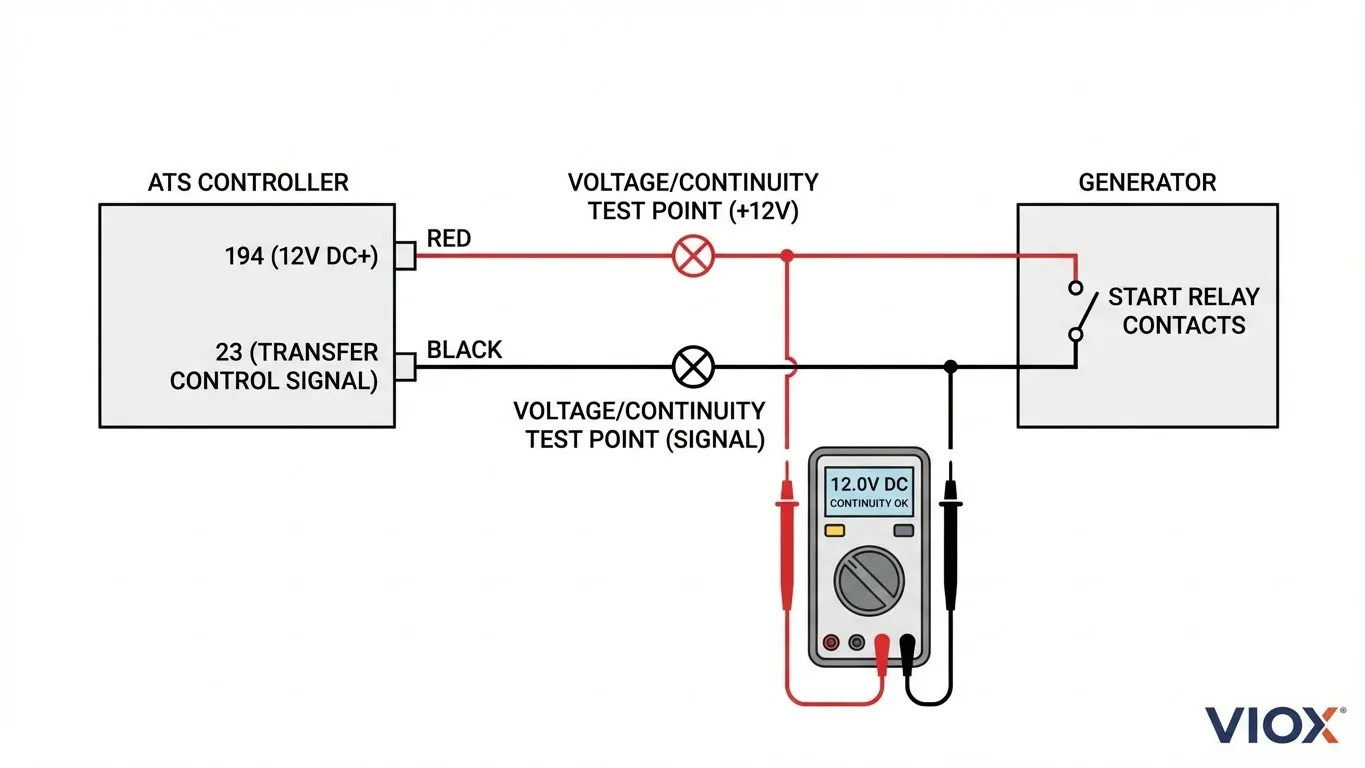
Most standby generators use a simple dry contact closure to initiate starting. The ATS controller provides two wires:
- Wire 194 – 12V DC positive (constant when in AUTO mode)
- Wire 23 – Control signal (grounded to initiate transfer)
When utility power fails, the ATS grounds wire 23 to the generator’s common ground. This completes the start circuit and signals the generator to crank.
For detailed wiring specifications, see our Hybrid Inverter ATS Wiring Guide.
Diagnostic Procedure
Tools needed: Digital multimeter, insulated screwdrivers
Step 1: Verify Control Power
- Set multimeter to DC voltage
- Measure between terminal 194 (at ATS) and ground
- Expected reading: 12-14V DC
- If 0V: Check 7.5A controller fuse, verify battery connections
Step 2: Test Start Signal
- Simulate power outage (turn off utility breaker)
- Wait for Time Delay Engine Start (TDES) to expire
- Measure between terminal 23 and ground
- Expected reading: 0V (grounded signal) or 12V (depending on system type)
Step 3: Manual Start Test
- At the generator terminal board, temporarily jumper the two start wires together
- Generator should crank immediately
- If it starts: Problem is in ATS control signal
- If it doesn’t start: Problem is in generator control or engine
Common 2-Wire Start Failures
| Symptom | Probable Cause | Solution |
|---|---|---|
| No voltage on 194 | Blown fuse, dead battery, bad wiring | Check F1 fuse (7.5A), test battery |
| 194 has voltage but no start | Wire 23 not grounding | Replace ATS control board |
| Intermittent starting | Loose terminal connections | Re-torque all connections to spec |
| Generator starts then stops | Incorrect wiring polarity | Verify 2-wire start configuration |
Understanding dry vs. wet contacts is essential for proper ATS installation and troubleshooting.
Phase 3: Generator Starts But ATS Won’t Switch
This is the most frustrating scenario: the generator is running perfectly, producing power—but the ATS refuses to transfer the load. The culprit is almost always voltage or frequency sensing.
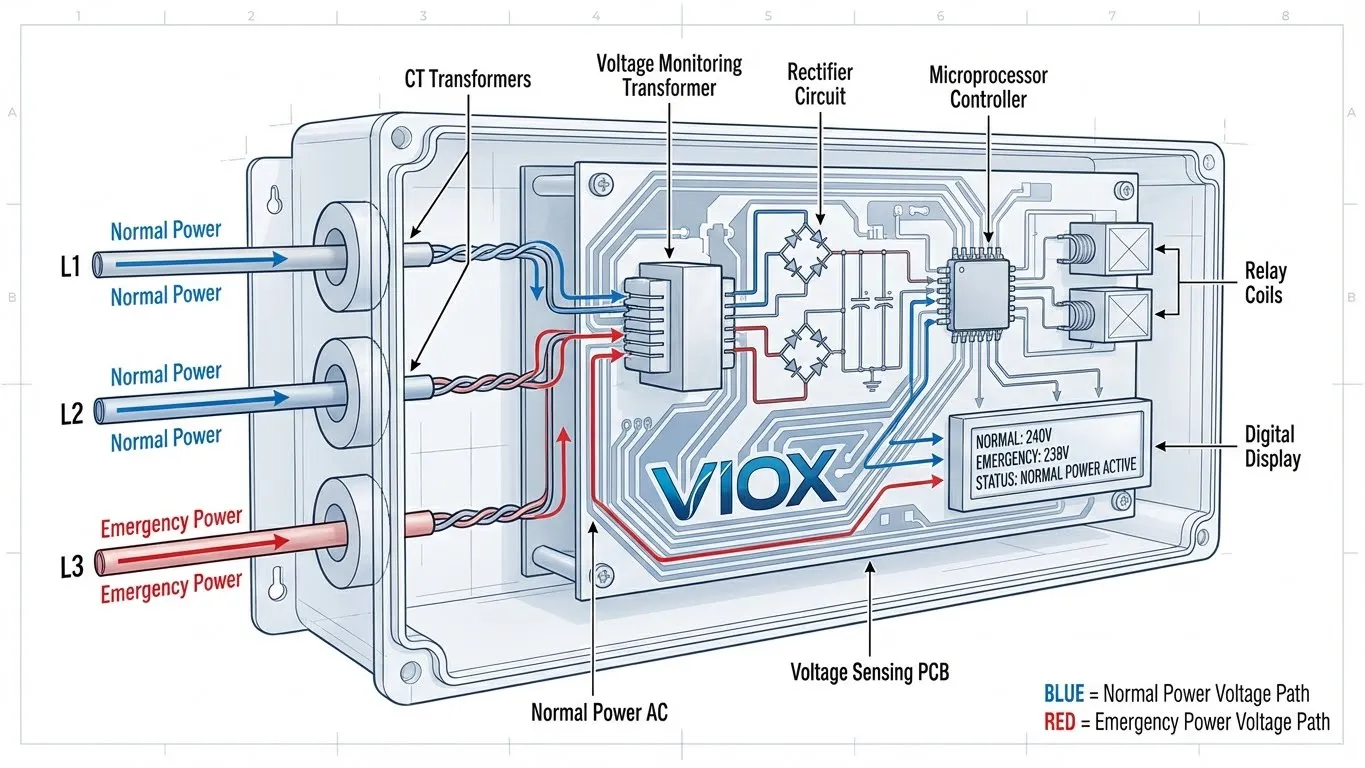
The Voltage/Frequency Protection Mechanism
ATS controllers include protective logic to prevent transferring to unstable generator power. The controller continuously monitors:
Voltage Acceptance Windows:
| Voltage Parameter | Typical Range | Notes |
|---|---|---|
| Minimum pickup | 85-90% nominal | Too low = won’t transfer |
| Maximum pickup | 110-115% nominal | Too high = won’t transfer |
| Transfer threshold | 90-95% nominal | Stable power required |
| Phase balance | Within 10V (3-phase) | Prevents single-phase operation |
Frequency Acceptance Windows:
| System | Acceptable Range | Notes |
|---|---|---|
| 60 Hz systems | 58-62 Hz | Governor adjustment required |
| 50 Hz systems | 48-52 Hz | Common outside North America |
Example scenario: Your generator nameplate says 240V, but the output at the ATS terminals measures only 190V during no-load running. The ATS controller sees this as unstable power and refuses to transfer, even though the generator “sounds fine.”
Diagnostic Procedure
Step 1: Measure Generator Output
- Start generator manually
- Allow 30-second warm-up
- Measure voltage at ATS emergency terminals (E1, E2)
- Check all phases (L1-N, L2-N, L1-L2 for single-phase; all six combinations for 3-phase)
Step 2: Check Frequency
- Use multimeter with frequency function
- Measure at generator output
- Expected: 59.5-60.5 Hz (North America) or 49.5-50.5 Hz (international)
- If out of range: Adjust engine governor
Step 3: Voltage Adjustment
- Locate generator AVR (Automatic Voltage Regulator)
- Adjust potentiometer while monitoring output
- Target 240V ±5% (or nameplate voltage)
Voltage Sensing Wire Issues
Many installers overlook the utility sensing wires (typically labeled N1/N2). These small-gauge wires carry 240V signals from the utility panel to the generator controller, allowing it to detect power failures.
Common problems:
- Wires disconnected during maintenance
- Incorrect voltage (208V fed to 240V sensing input)
- Loose connections causing intermittent sensing
- Damaged wires from rodents or physical damage
Phase 4: Understanding Timers & Delays
“It’s not broken—it’s just counting down.”
ATS systems incorporate multiple time delays to protect equipment and ensure stable operation. Premature troubleshooting often occurs because technicians don’t wait for these programmed delays.
Standard ATS Time Delays
| Timer Function | Typical Setting | Purpose |
|---|---|---|
| Time Delay Engine Start (TDES) | 1-5 seconds | Prevents nuisance starts from momentary outages |
| Engine Warm-up | 15-30 seconds | Allows oil pressure and temperature to stabilize |
| Time Delay Switching (TDS) | 0-5 seconds | Ensures generator voltage/frequency are stable |
| Retransfer Delay | 30-300 seconds | Confirms utility power is truly restored |
| Engine Cooldown | 5-30 minutes | Allows gradual unloaded shutdown |
The Complete Transfer Sequence Timeline
Understanding the full sequence prevents premature diagnosis:
- T+0 seconds: Utility power failure detected
- T+1-5 sec: TDES expires, ATS sends start signal
- T+5-10 sec: Generator cranks and starts
- T+10-40 sec: Engine warm-up, building oil pressure
- T+40-45 sec: Voltage and frequency reach acceptable range
- T+45 sec: ATS transfers load to generator
Total elapsed time: 45-60 seconds from utility failure to restored power
If you’re testing the system and getting impatient at 30 seconds, you may incorrectly conclude the system has failed when it’s simply following its programmed sequence.
Adjusting Time Delays
Most modern ATS controllers allow adjustment of these parameters:
- Access controller menu (consult manual for key sequence)
- Navigate to “Settings” or “Time Delays”
- Adjust values within acceptable ranges
- CAUTION: NEC 700.12 limits total transfer time to 10 seconds for life safety loads
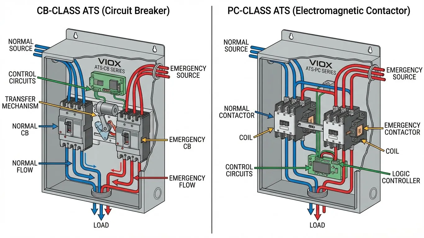
Phase 5: CB Class vs. PC Class Failure Modes
The type of ATS you have determines both the failure modes and troubleshooting approach.
Circuit Breaker Class (CB) ATS
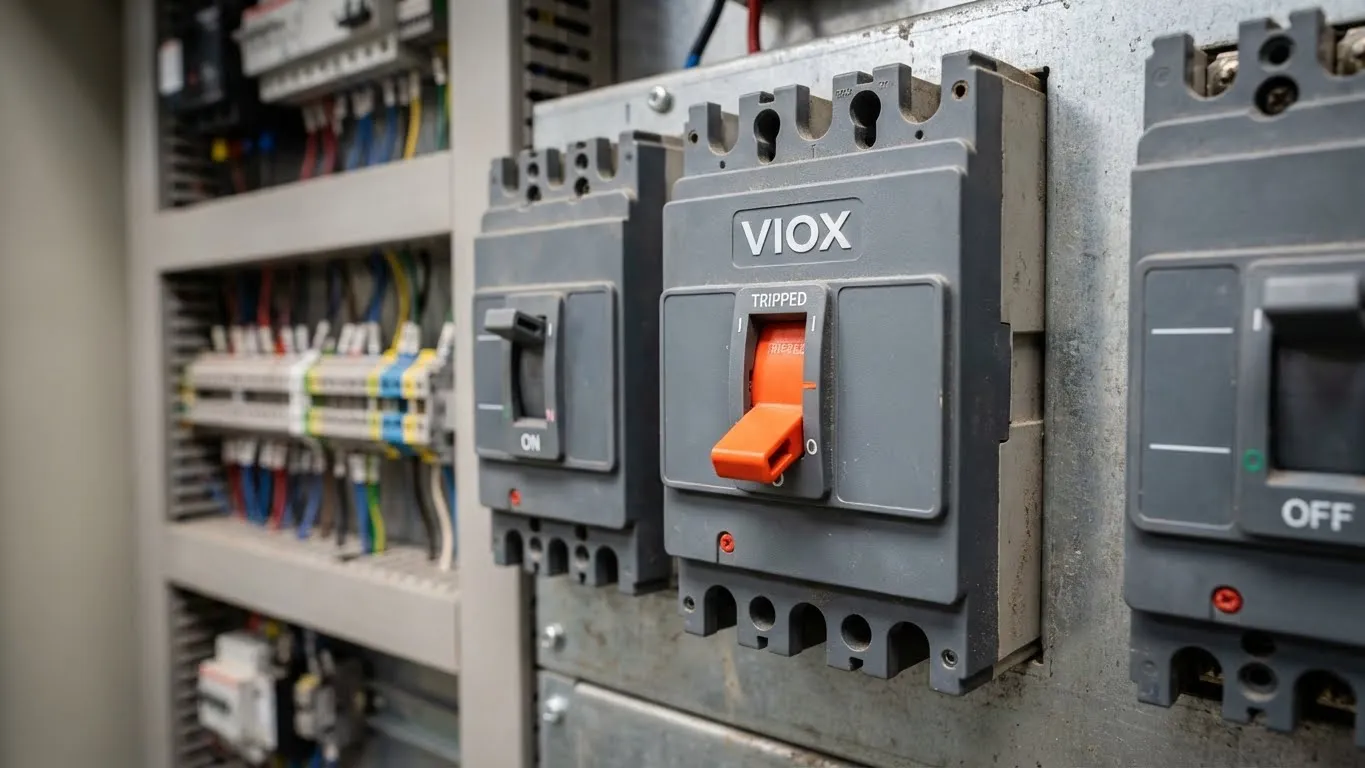
How it works: Uses standard molded-case circuit breakers (MCCBs) as the switching mechanism. Breakers physically open and close to transfer power.
Common CB-Class Failures:
| Problem | Cause | Solution |
|---|---|---|
| Won’t transfer to generator | Emergency breaker tripped | Reset breaker manually |
| Transfers but no power | Breaker contacts worn | Replace breaker |
| Won’t retransfer to utility | Normal breaker tripped | Reset breaker |
| Frequent nuisance trips | Overload or short circuit | Check load calculation |
Troubleshooting tip: CB-class breakers can trip from overload, short circuit, or mechanical wear. The breaker handle will be in the middle “tripped” position—not fully ON or OFF. You must manually reset it even after the fault clears.
Power Contactor Class (PC) ATS
How it works: Uses electromagnetic contactors (heavy-duty relays) to make and break the power connection. No manual reset required.
Common PC-Class Failures:
| Problem | Cause | Solution |
|---|---|---|
| Loud buzzing sound | Low control voltage | Check 12V supply to coils |
| Won’t transfer | Coil burned out | Replace contactor |
| Chattering | Loose wire connections | Re-torque terminal screws |
| Contacts welded closed | Sustained overload/short | Replace entire contactor assembly |
For detailed comparison, review the PC Class vs. CB Class selection guide.
Which Class is Right for Your Application?
| Requirement | Recommended Class |
|---|---|
| Life safety loads (hospitals, fire pumps) | PC Class |
| Budget-conscious installations | CB Class |
| Frequent transfers (>10/month) | PC Class |
| Heavy inrush loads (motors >50HP) | PC Class |
| Simple maintenance by non-specialists | CB Class |
Advanced Troubleshooting: When Standard Methods Fail
Controller Board Failures
Modern ATS systems rely on microprocessor-based controllers. When these fail, symptoms include:
- Erratic transfers (switching back and forth)
- No response to utility power loss
- Error codes that don’t match actual conditions
- Display showing incorrect voltage/frequency readings
Test procedure:
- Measure incoming voltages directly at terminals (bypass controller)
- If voltages are correct but display shows errors, controller is faulty
- Check for water damage, corrosion, or physical damage to PCB
- Replacement cost: $200-$800 depending on model
Mechanical Linkage Problems
In mechanically-operated switches, the control signal energizes a motor or solenoid that physically moves the transfer mechanism. Failures include:
- Jammed mechanism (requires inspection with power OFF)
- Worn mechanical stops or cams
- Broken return springs
- Seized bearings or pivot points
These require visual inspection by a qualified technician with all power sources de-energized.
Communication Failures (Smart ATS Systems)
Advanced ATS units communicate with building management systems via Modbus, BACnet, or proprietary protocols. Communication failures can prevent remote monitoring but typically don’t affect automatic operation unless configured for remote control.
Safety Critical: What NOT to Do
⚠️ DANGER: Automatic transfer switches contain lethal voltages from two sources simultaneously. Only qualified electricians should perform internal inspections.
Never attempt:
- Opening enclosure with utility power connected
- Bypassing safety interlocks
- “Hot-swapping” control boards or components
- Testing with loads connected unless properly trained
- Adjusting internal mechanisms without lockout/tagout procedures
Always:
- Use appropriate PPE (arc-rated clothing, insulated gloves, face shield)
- Follow NFPA 70E guidelines for electrical safety
- Implement lockout/tagout on both normal and emergency sources
- Use a qualified electrician for all service work
Preventive Maintenance: Stopping Problems Before They Start
The best troubleshooting is prevention. Implement these practices:
Monthly:
- Visual inspection for signs of overheating, discoloration
- Check indicator lights and display for error codes
- Verify automatic exercise cycle completed successfully
Quarterly:
- Inspect all wire terminations for tightness
- Clean dust and debris from enclosure
- Test manual operation (with proper safety procedures)
Annually:
- Full load transfer test under actual outage conditions
- Measure voltage drop across main contacts
- Calibrate voltage and frequency sensing if adjustable
- Verify all time delay settings match specifications
- Professional inspection by licensed electrician
Product Recommendation: VIOX ATS Series
For reliable backup power transfer, VIOX offers commercial-grade automatic transfer switches designed for industrial and commercial applications. Our ATS units feature:
- Microprocessor-based controllers with self-diagnostics
- Wide voltage and frequency acceptance windows
- Programmable time delays for optimized performance
- Available in both CB and PC class configurations
- UL 1008 listed and NFPA 110 compliant
Explore the full VIOX ATS product line for specifications and technical data.
Troubleshooting Flowchart Summary
Utility Power Fails
         ↓
Generator Starts? → NO → Check 2-wire start circuit (Phase 2)
         ↓ YES
         ↓
ATS Transfers? → NO → Check voltage/frequency (Phase 3)
         ↓ YES
         ↓
Stable Operation? → NO → Check time delays (Phase 4)
         ↓ YES
         ↓
System Operating Normally
FAQ: Common ATS Questions
Q: How long should I wait before troubleshooting an ATS that hasn’t transferred?
A: Allow at least 60 seconds for the complete transfer sequence. Time Delay Engine Start (TDES) plus engine warm-up can total 30-45 seconds alone. Premature troubleshooting wastes time and can lead to incorrect diagnosis.
Q: My generator runs during weekly tests but won’t transfer during real outages. Why?
A: Exercise mode often bypasses the actual transfer operation. The issue is likely in the transfer mechanism itself (CB-class breaker tripped, PC-class contactor failure) or in the voltage/frequency sensing circuit. The generator is fine—the ATS switching is the problem.
Q: Can I test an ATS without shutting off power to my building?
A: Yes, most ATS units have a TEST mode that simulates utility failure without disconnecting actual power. Consult your specific model’s manual. However, a full load transfer test under actual outage conditions is the only way to verify complete system operation.
Q: What’s the difference between “time delay engine start” and “time delay switching”?
A: TDES delays the start signal to the generator (typically 1-5 seconds) to prevent nuisance starts from momentary power blips. TDS delays the actual load transfer after the generator reaches acceptable voltage/frequency (typically 0-5 seconds) to ensure stable power before switching. Both protect equipment but serve different purposes.
Q: My ATS transfers to generator but won’t transfer back to utility. What’s wrong?
A: Check the retransfer delay timer—it may be set for several minutes to ensure utility power has truly stabilized. Also verify all three phases of utility power are present (for 3-phase systems). If utility voltage is fluctuating, the ATS will refuse to retransfer until it detects stable power.
Q: Should I choose CB-class or PC-class for my facility?
A: PC-class is recommended for critical loads (hospitals, data centers) and applications with frequent transfers. CB-class is cost-effective for less critical applications with infrequent transfers. Review our comprehensive comparison guide to determine which class fits your requirements.
Professional installation and maintenance of automatic transfer switches requires qualified electrical contractors. VIOX Electric provides technical support for all ATS installations—contact our engineering team for application-specific guidance.
