
Understanding Temperature Rise in Circuit Breakers: Why It Matters
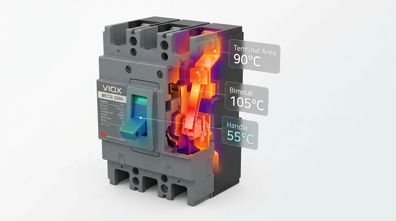
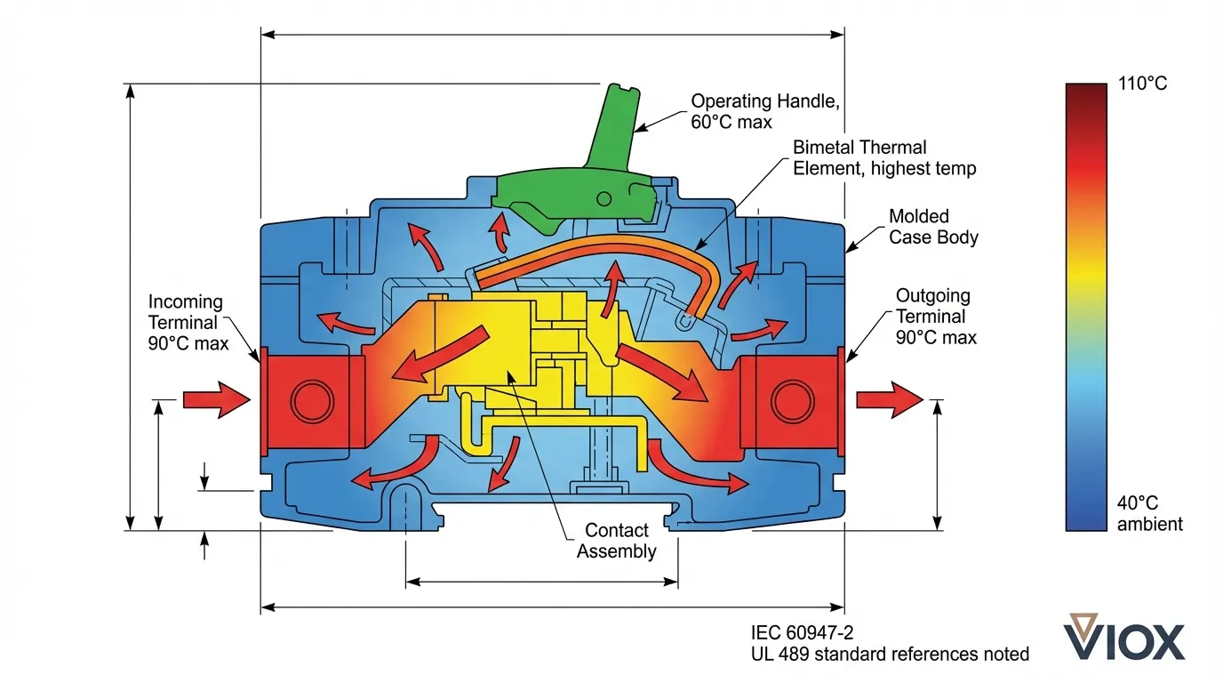
Every circuit breaker generates heat during normal operation. When electrical current flows through the internal components—contacts, bimetal strips, and terminals—resistance creates thermal energy. While some heating is inevitable, excessive temperature rise can degrade insulation, accelerate contact wear, cause nuisance tripping, and ultimately lead to catastrophic failure.
For electrical engineers and panel builders specifying MCBs and MCCBs, understanding temperature rise limits isn’t just about compliance—it’s about ensuring long-term reliability and safety. Both IEC 60947-2 (for MCCBs) and UL 489 (North American standard) establish precise thermal performance requirements that manufacturers like VIOX must meet through rigorous type testing.
Temperature Rise vs. Absolute Temperature: Critical Distinction
Before diving into specific limits, it’s essential to understand the difference between temperature rise (ΔT) and absolute temperature:
- Temperature Rise (ΔT): The increase in temperature above ambient conditions, measured in degrees Celsius or Fahrenheit
- Absolute Temperature: The actual measured temperature of a component, combining ambient temperature plus temperature rise
Most standards specify temperature rise limits assuming a standard calibration temperature of 40°C (104°F). This means:
Absolute Temperature = Ambient Temperature + Temperature Rise
For example, a terminal with a 50°C rise limit operating in a 40°C ambient would reach an absolute temperature of 90°C—the maximum safe operating point for many conductor insulation types.
UL 489 Temperature Rise Requirements
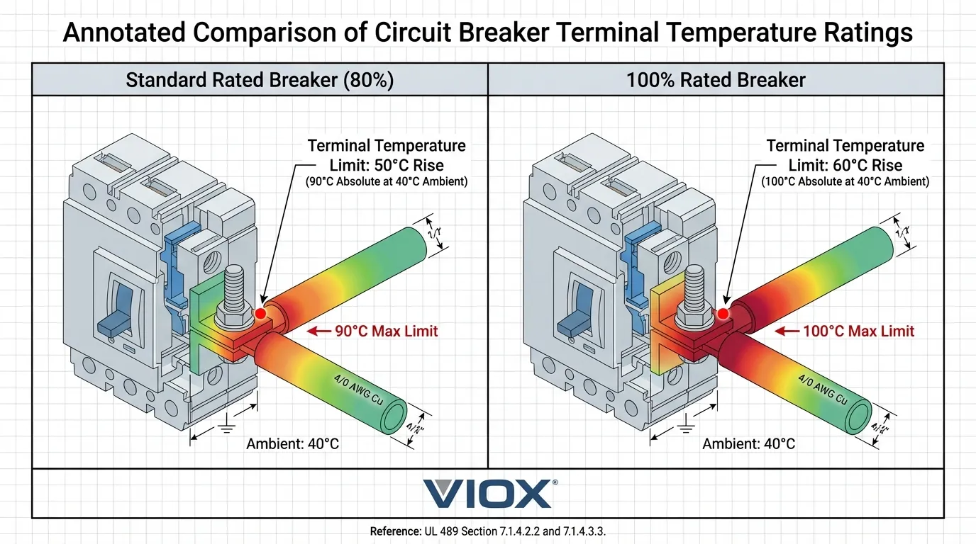
UL 489 establishes comprehensive thermal testing requirements for molded case circuit breakers used in North American installations. The standard differentiates between standard-rated (80% continuous) and 100%-rated breakers.
Table 1: UL 489 Temperature Rise Limits Summary
| Component/Location | Standard Rated Breaker (80%) | 100% Rated Breaker | Reference Clause |
|---|---|---|---|
| Wiring Terminals | 50°C rise (90°C absolute at 40°C ambient) | 60°C rise (100°C absolute at 40°C ambient) | UL 489 §7.1.4.2.2 / §7.1.4.3.3 |
| Metallic Handles/Knobs | 60°C maximum absolute | 60°C maximum absolute | UL 489 §7.1.4.1.6 |
| Non-metallic Handles/Knobs | 85°C maximum absolute | 85°C maximum absolute | UL 489 §7.1.4.1.6 |
| Internal Contacts | No specific limit (tested for endurance) | No specific limit (tested for endurance) | UL 489 §8.7 |
| Enclosure Surface | Varies by material and location | Varies by material and location | UL 489 §7.1.4 |
Key Insight: The 10°C difference in terminal temperature rise between standard and 100% rated breakers (50°C vs. 60°C) reflects the additional thermal stress when operating continuously at full rated current. This is why 100% rated breakers require enhanced terminal design and heat dissipation.
IEC 60947-2 and IEC 60898-1 Temperature Requirements
International standards take a similar but slightly different approach to thermal performance:
Table 2: IEC 60947-2 vs IEC 60898-1 Temperature Requirements Comparison
| Parameter | IEC 60947-2 (MCCBs – Industrial) | IEC 60898-1 (MCBs – Residential) | Key Difference |
|---|---|---|---|
| Reference Ambient | 40°C (can be 30°C for some applications) | 30°C standard reference | Industrial vs. residential calibration |
| Terminal Temperature Rise | 50-70°C depending on terminal type | 60°C for screw terminals | Material-specific limits |
| Operating Handle | 55°C rise (metallic), 70°C rise (insulating) | Similar requirements | User contact safety |
| Enclosure Surface | 60-80°C rise depending on material | 60°C rise typical | Varies by pollution degree |
| Thermal Trip Calibration | At rated current, 40°C ambient | At rated current, 30°C ambient | Affects derating factors |
Critical Note: IEC 60947-2 applies to molded case circuit breakers (MCCBs) designed for industrial applications with higher fault levels and more demanding environmental conditions, while IEC 60898-1 governs miniature circuit breakers for residential and light commercial use.
Absolute Maximum Temperatures at Different Ambient Conditions
Real-world installations rarely operate at the standard 40°C calibration temperature. Understanding absolute temperature limits across various ambient conditions is crucial for proper application.
Table 3: Absolute Maximum Temperatures at Different Ambient Conditions
| Ambient Temperature | Standard Rated Terminal (50°C rise) | 100% Rated Terminal (60°C rise) | Metallic Handle (60°C max) | Non-metallic Handle (85°C max) |
|---|---|---|---|---|
| 25°C (77°F) | 75°C (167°F) | 85°C (185°F) | 60°C (140°F) | 85°C (185°F) |
| 30°C (86°F) | 80°C (176°F) | 90°C (194°F) | 60°C (140°F) | 85°C (185°F) |
| 40°C (104°F) | 90°C (194°F) | 100°C (212°F) | 60°C (140°F) | 85°C (185°F) |
| 50°C (122°F) | 100°C (212°F) ⚠️ | 110°C (230°F) ⚠️ | 60°C (140°F) | 85°C (185°F) |
| 60°C (140°F) | 110°C (230°F) ❌ | 120°C (248°F) ❌ | 60°C (140°F) | 85°C (185°F) |
⚠️ = Requires derating or enhanced cooling
❌ = Exceeds typical conductor insulation ratings (90°C THHN/XHHW)
Important: At elevated ambient temperatures, terminals can exceed the temperature rating of standard 75°C or 90°C conductor insulation. This is why electrical derating for temperature becomes critical in hot environments.
Thermal Testing Procedures and Calibration
Both UL 489 and IEC 60947-2 require manufacturers to conduct extensive thermal testing:
- Test Setup: Breakers are mounted in their intended configuration (enclosed or open) and loaded to rated current
- Stabilization Period: Minimum 3 hours of continuous operation until thermal equilibrium is reached
- Measurement Points: Thermocouples placed at terminals, handles, and enclosure surfaces
- Ambient Control: Testing conducted at 40°C ambient (UL 489) or per manufacturer’s declared reference temperature (IEC)
- Pass/Fail Criteria: All measurement points must remain below specified temperature rise limits
VIOX conducts thermal testing on every circuit breaker design in our accredited laboratories, ensuring compliance with both IEC and UL requirements. This dual certification allows our products to serve global markets with confidence.
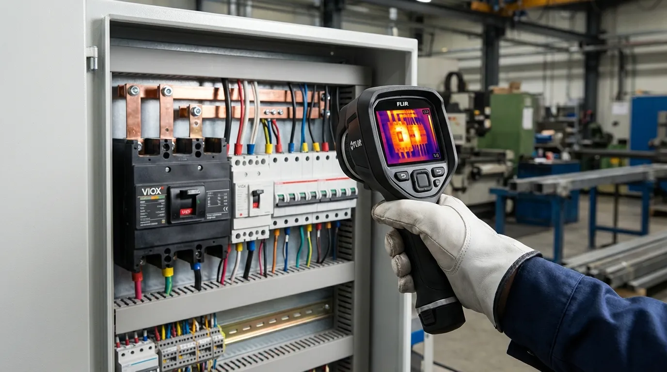
Infrared Thermography: Practical Temperature Monitoring
Infrared (IR) thermography has become the industry standard for non-invasive circuit breaker temperature monitoring. However, proper interpretation requires understanding both the technology and the standards.
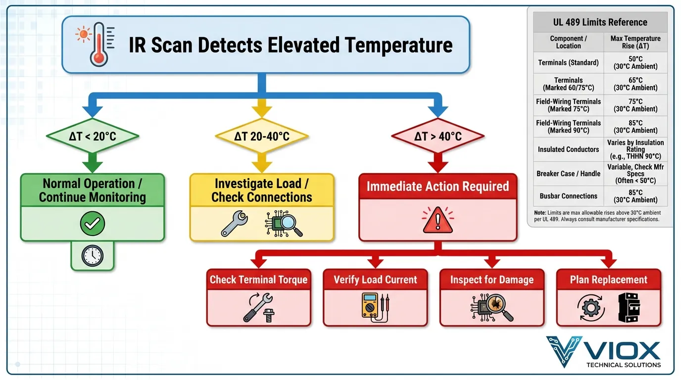
Table 4: IR Thermography Interpretation Guide
| Temperature Rise (ΔT) | Thermal Signature | Recommended Action | Urgency Level |
|---|---|---|---|
| 0-10°C above ambient | Green/Blue on thermal image | Normal operation; document baseline | Routine |
| 10-20°C above ambient | Yellow on thermal image | Monitor trend; verify load is within rating | Low Priority |
| 20-30°C above ambient | Orange on thermal image | Investigate connections; check terminal torque; verify conductor sizing | Medium Priority |
| 30-40°C above ambient | Red on thermal image | Schedule immediate inspection; check for loose connections, corrosion, or overloading | High Priority |
| >40°C above ambient | Dark red/white on thermal image | Immediate action required; potential safety hazard; plan replacement | Critical |
Best Practices for IR Scanning:
- Allow minimum 3 hours of steady-state operation before scanning
- Measure ambient temperature separately for accurate ΔT calculation
- Compare similar breakers under similar loads to identify outliers
- Document readings over time to identify degradation trends
- Consider emissivity settings (typically 0.95 for painted surfaces, 0.3-0.5 for bare copper)
Troubleshooting Hot Circuit Breakers
When thermal imaging or physical inspection reveals elevated temperatures, systematic troubleshooting is essential.
Table 5: Troubleshooting Guide – Temperature vs Problem Diagnosis
| Symptom | Likely Cause | Diagnostic Steps | Solution |
|---|---|---|---|
| Hot terminals only | Loose connection, undersized conductor, high resistance joint | Check torque specs; inspect for corrosion; verify conductor ampacity | Re-torque terminals; clean contacts; upsize conductor if needed |
| Hot breaker body | Overload condition, degraded bimetal, internal contact wear | Measure actual load current; compare to breaker rating; check trip curve | Reduce load; replace breaker if near end of life |
| Hot handle | Internal heat transfer from contacts/bimetal (normal to some degree) | Verify handle temperature is <60°C (metallic) or <85°C (non-metallic) | If within limits, no action; if exceeded, replace breaker |
| Entire panel hot | Inadequate ventilation, excessive grouping, high ambient | Check enclosure ventilation; measure ambient inside panel; review derating factors | Improve ventilation; add cooling; derate breakers per NEC/IEC |
| One breaker significantly hotter than identical neighbors | Internal defect, contact degradation, calibration drift | Compare temperatures of similar breakers under similar loads | Replace suspect breaker; investigate root cause |
When to Replace: If a breaker consistently operates above its temperature rise limits even under proper loading conditions, replacement is mandatory. Continuing to operate overheated breakers risks insulation failure, fire, or loss of overcurrent protection. Learn more about identifying bad circuit breakers.
Conductor Insulation Compatibility
A critical but often overlooked aspect of temperature rise limits is their relationship to conductor insulation ratings. The NEC and IEC standards require that conductor insulation temperature ratings match or exceed the terminal temperature.
Common Conductor Insulation Types:
- 60°C (140°F): TW, UF (older installations)
- 75°C (167°F): THW, THWN, RHW, USE
- 90°C (194°F): THHN, THWN-2, XHHW-2, RHH, RHW-2
For standard-rated breakers with 50°C rise (90°C absolute at 40°C ambient), 90°C insulation provides adequate margin. However, 60°C insulation would be inadequate and could fail prematurely.
Key Rule: Always verify that conductor insulation temperature rating ≥ terminal absolute temperature under maximum expected ambient conditions. This is particularly important in hot environments or when using 100% rated breakers.
IEC vs UL Standards: Key Differences
While IEC 60947-2 and UL 489 share similar objectives, several important differences affect product selection:
| Aspect | IEC 60947-2 | UL 489 | Impact |
|---|---|---|---|
| Reference Ambient | 40°C (can vary) | 40°C (fixed) | IEC allows manufacturer-declared reference |
| Terminal Rise Limits | Material-dependent (50-70°C) | Fixed (50°C standard, 60°C for 100%) | IEC more flexible based on terminal construction |
| Enclosure Testing | Tested in representative enclosure | Tested in smallest likely enclosure | UL potentially more conservative |
| Continuous Rating | 100% continuous by default | 80% continuous unless marked 100% | IEC breakers generally more robust for continuous duty |
| Derating Guidance | Manufacturer-provided curves | NEC provides application guidance | Different approaches to high-temperature environments |
For panel builders serving global markets, VIOX offers circuit breakers certified to both standards, ensuring compliance regardless of installation location. Our quality assurance processes verify thermal performance to the most stringent requirements.
Practical Application Guidelines
For Panel Builders:
- Always verify breaker temperature ratings match your application environment
- Account for enclosure heating effects—interior ambient can be 10-20°C above room temperature
- Use thermal imaging during commissioning to establish baseline temperatures
- Implement periodic IR scanning as part of preventive maintenance programs
- Document all temperature readings for trend analysis
For Facility Managers:
- Schedule annual thermal surveys of critical electrical distribution equipment
- Train maintenance personnel to recognize abnormal thermal patterns
- Establish temperature thresholds that trigger investigation (typically ΔT > 20°C)
- Maintain records of IR scans to identify degradation trends
- Budget for proactive replacement of breakers showing thermal degradation
For Electrical Contractors:
- Verify terminal torque specifications during installation—loose connections are the #1 cause of hot terminals
- Use anti-oxidant compound on aluminum conductors to prevent high-resistance joints
- Allow adequate spacing between breakers in panels to promote heat dissipation
- Consider ambient temperature derating in hot environments
- Document installation conditions for future reference
FAQ: Circuit Breaker Temperature Rise
Q: What is the maximum safe temperature for a circuit breaker terminal?
A: For standard-rated breakers per UL 489, terminals should not exceed 90°C absolute temperature (50°C rise above 40°C ambient). For 100%-rated breakers, the limit is 100°C absolute (60°C rise). IEC 60947-2 has similar limits but may vary based on terminal material and construction. Always verify the specific breaker’s datasheet.
Q: How do I know if my circuit breaker is running too hot?
A: Use infrared thermography to measure the temperature rise above ambient. If ΔT exceeds 30°C, investigate immediately. Physical signs include discolored insulation near terminals, a burning smell, or buzzing/humming sounds. If the breaker handle is uncomfortably hot to touch (>60°C for metal, >85°C for plastic), it may be operating outside normal parameters.
Q: What’s the difference between temperature rise and absolute temperature?
A: Temperature rise (ΔT) is the increase above ambient temperature, while absolute temperature is the actual measured temperature. For example, a terminal at 85°C in a 40°C ambient has a 45°C temperature rise. Standards specify rise limits because ambient conditions vary, but absolute temperature determines insulation compatibility.
Q: Can I use a 60°C rated wire on a circuit breaker terminal?
A: Generally no, unless the breaker is specifically rated for 60°C terminations and operates in a controlled environment. Most modern breakers assume 75°C minimum conductor insulation. With a 50°C terminal rise at 40°C ambient, you’d reach 90°C absolute—well above 60°C insulation limits. Always match or exceed the terminal temperature rating.
Q: How long should I wait before taking IR readings on a breaker?
A: Allow minimum 3 hours of continuous operation at steady load for the breaker to reach thermal equilibrium. Thermal mass in the breaker and surrounding enclosure takes time to stabilize. For critical measurements, 4-6 hours is preferable. Taking readings too early will underestimate actual operating temperatures.
Q: What does UL 489 say about 100% rated breakers?
A: UL 489 Paragraph 7.1.4.3.3 allows 100%-rated breakers to have terminal temperature rise up to 60°C (vs. 50°C for standard breakers), resulting in 100°C absolute temperature at 40°C ambient. These breakers must be specifically marked “Suitable for Continuous Operation at 100% of Rating” and typically feature enhanced terminal designs and heat dissipation.
Key Takeaways
- Temperature rise limits are safety-critical: UL 489 and IEC 60947-2 establish maximum temperature rise values to prevent insulation failure, contact degradation, and fire hazards in circuit breakers.
- Standard vs. 100% rated breakers differ by 10°C: Standard breakers allow 50°C terminal rise (90°C absolute at 40°C ambient), while 100% rated breakers permit 60°C rise (100°C absolute)—a crucial difference for continuous-duty applications.
- Absolute temperature = Ambient + Rise: Always calculate absolute terminal temperature based on actual ambient conditions, not just the standard 40°C calibration temperature, especially in hot environments.
- Conductor insulation must match terminal temperature: Use 90°C rated conductors (THHN, XHHW-2) for modern breakers; 60°C insulation is inadequate for most applications and violates code requirements.
- IR thermography requires 3+ hours stabilization: Thermal imaging is only accurate after circuit breakers reach thermal equilibrium—premature readings underestimate actual operating temperatures.
- ΔT > 30°C demands immediate investigation: Temperature rise exceeding 30°C above ambient indicates loose connections, overloading, or internal degradation requiring prompt corrective action.
- IEC and UL standards align on fundamentals: While test procedures differ slightly, both IEC 60947-2 and UL 489 target similar terminal temperature limits, ensuring global safety standards.
- Preventive maintenance prevents failures: Regular thermal surveys, proper terminal torque, and trend analysis identify problems before they cause downtime or safety incidents—invest in IR equipment and training.
For reliable circuit protection that meets the most stringent thermal performance requirements, explore VIOX’s complete line of MCBs and MCCBs engineered to IEC and UL standards. Our technical team can assist with product selection, thermal analysis, and application-specific guidance to ensure your installations operate safely within temperature limits.
