
Selecting the right molded case circuit breaker (MCCB) starts with understanding standard breaker sizes. Unlike miniature circuit breakers (MCBs) that protect final circuits, MCCBs cover a much wider current range—from 16A branch feeders to 1600A main incomers—and choosing the correct rating directly impacts system safety, coordination, and project costs.
This guide maps the complete IEC 60947-2 standard current ratings, explains frame size categories, and shows you how to match breaker specifications to your application. Whether you’re sizing a motor feeder, a building sub-main, or a switchgear incomer, you’ll find the technical details and selection logic you need.
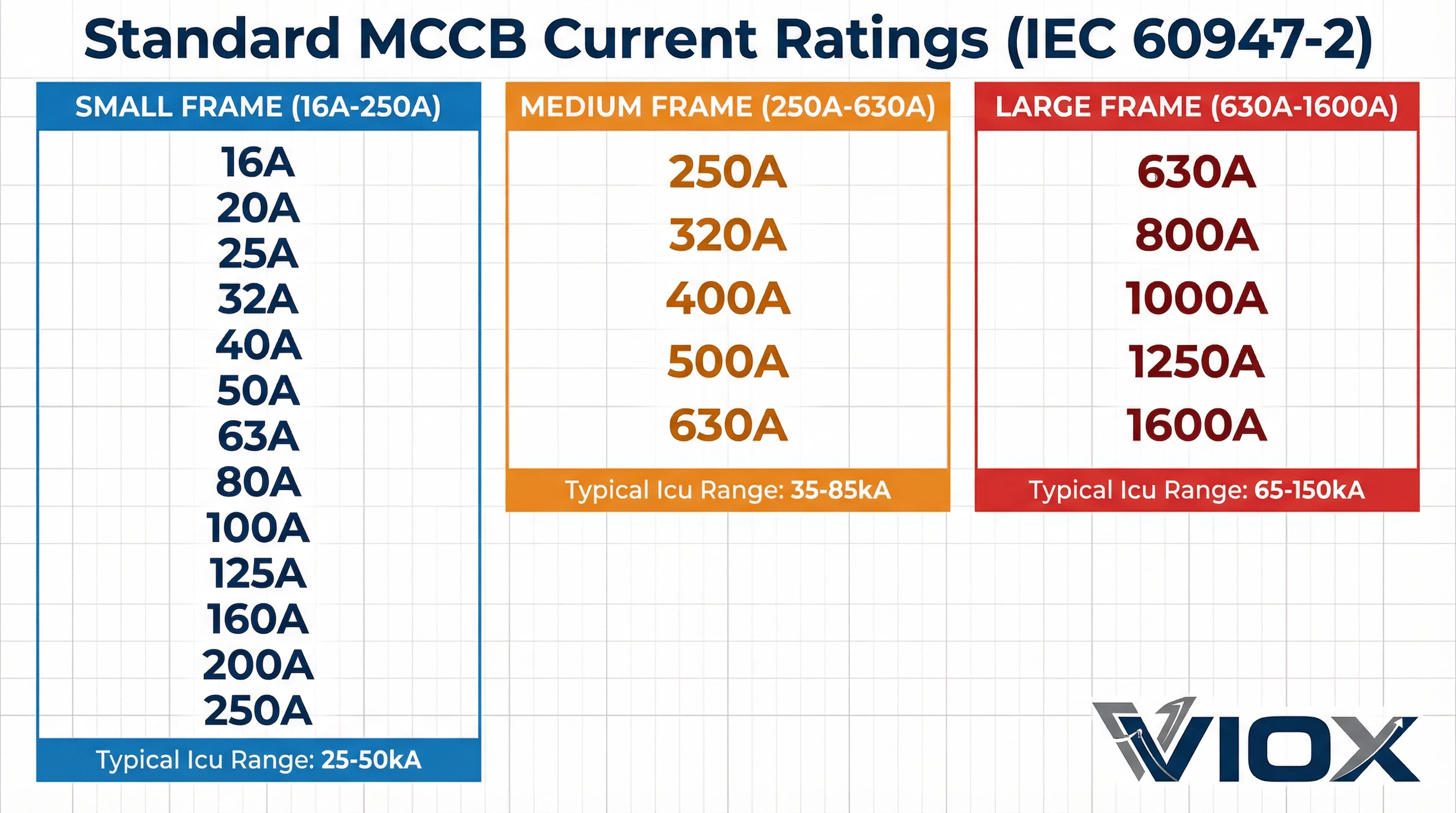
Quick Reference: Standard MCCB Current Ratings
IEC-compliant MCCBs are available in these standard ratings:
16A | 20A | 25A | 32A | 40A | 50A | 63A | 80A | 100A | 125A | 160A | 200A | 250A | 320A | 400A | 500A | 630A | 800A | 1000A | 1250A | 1600A
Not every manufacturer offers every rating in every frame. The frame size (small, medium, or large) determines which current ratings are available and what breaking capacities (Icu/Ics) the breaker can achieve.
Understanding IEC 60947-2 Standard Ratings
IEC 60947-2 is the international standard that defines performance requirements for low-voltage circuit breakers, including all MCCBs. When you see “IEC 60947-2” marked on a breaker nameplate, it confirms the device has been tested and certified to meet specific electrical, mechanical, and safety criteria.
Key Rating Parameters
Every MCCB datasheet includes these essential ratings:
In (Rated Current): The maximum continuous current the breaker can carry at a reference ambient temperature (typically 40°C) without tripping. This is the “size” of the breaker—for example, a 250A MCCB has In = 250A.
Ue (Rated Operational Voltage): The voltage at which the breaker is designed to operate. Common ratings include 230V, 400V, 690V AC for three-phase systems, or 250V DC for battery and solar applications.
Icu (Rated Ultimate Short-Circuit Breaking Capacity): The maximum fault current (in kA) the breaker can safely interrupt once. After an Icu-level fault, the breaker may not be fit for continued service. Typical values range from 25kA to 100kA depending on frame size.
Ics (Rated Service Short-Circuit Breaking Capacity): The fault current level at which the breaker can interrupt and remain serviceable for continued operation. IEC defines Ics as a percentage of Icu—usually 25%, 50%, 75%, or 100%. For critical facilities, specify Ics = 100%; for commercial buildings, 75% is standard practice.
Utilization Categories
IEC 60947-2 defines two categories:
- Category A: Breakers designed for instantaneous tripping with no intentional time delay. Most MCCBs fall into this category for general distribution and motor protection.
- Category B: Breakers with intentional time delay (withstand capability) for selective coordination with downstream devices. Used in upstream positions where you need selectivity.
Why These Ratings Matter
When sizing an MCCB, you must ensure:
- In matches or exceeds load current (with margin for inrush and future growth)
- Icu meets or exceeds prospective fault current at the installation point
- Ics is appropriate for the application criticality (75-100%)
- Frame size accommodates the required In and Icu combination
A 250A load does not automatically require a 250A breaker—you also need to verify the fault level, coordination requirements, and whether derating applies (high ambient temperature, grouping, or harmonic content).
MCCB Frame Size Categories
Frame Size Classification
While manufacturers use different naming conventions, the industry recognizes three broad categories:
| Frame Category | Typical Current Range | Typical Icu Range | Common Applications |
| Small Frame | 16A – 250A | 25kA – 50kA | Branch circuits, small feeders, motor protection |
| Medium Frame | 250A – 630A | 35kA – 70kA | Sub-mains, building feeders, distribution boards |
| Large Frame | 630A – 1600A | 50kA – 100kA | Main incomers, switchgear, industrial mains |
Why Frame Size Matters
Breaking Capacity Limits: Larger frames can interrupt higher fault currents. If your installation point has 65kA prospective fault current, you’ll need a medium or large frame—small frames typically max out at 50kA.
Physical Space: A 1600A large-frame MCCB can be 300mm wide or more, while a 63A small-frame breaker might be 70mm. Panel design must account for these dimensions, especially in retrofit projects.
Cost Optimization: Don’t over-specify. A 200A application with 30kA fault level doesn’t need a large-frame breaker. Use a small-frame 250A unit to save panel space and cost.
Adjustment Range: Electronic trip units in larger frames often allow field adjustment of In, Ir (thermal), and Im (magnetic) settings. Small frames with thermal-magnetic trips are typically fixed.
Frame vs. Rating: A Practical Example
Consider a 400A feeder in a commercial building with 40kA fault level:
- Option 1: Select a medium-frame MCCB rated 400A / 50kA (In=400A, Icu=50kA)
- Option 2: Select a large-frame MCCB rated 400A / 65kA (In=400A, Icu=65kA)
Both meet the 400A load requirement, but Option 1 uses a smaller, less expensive frame adequate for the 40kA fault level. Option 2 provides margin but wastes panel space and budget. The key is to choose the smallest frame that meets both your In and Icu requirements.
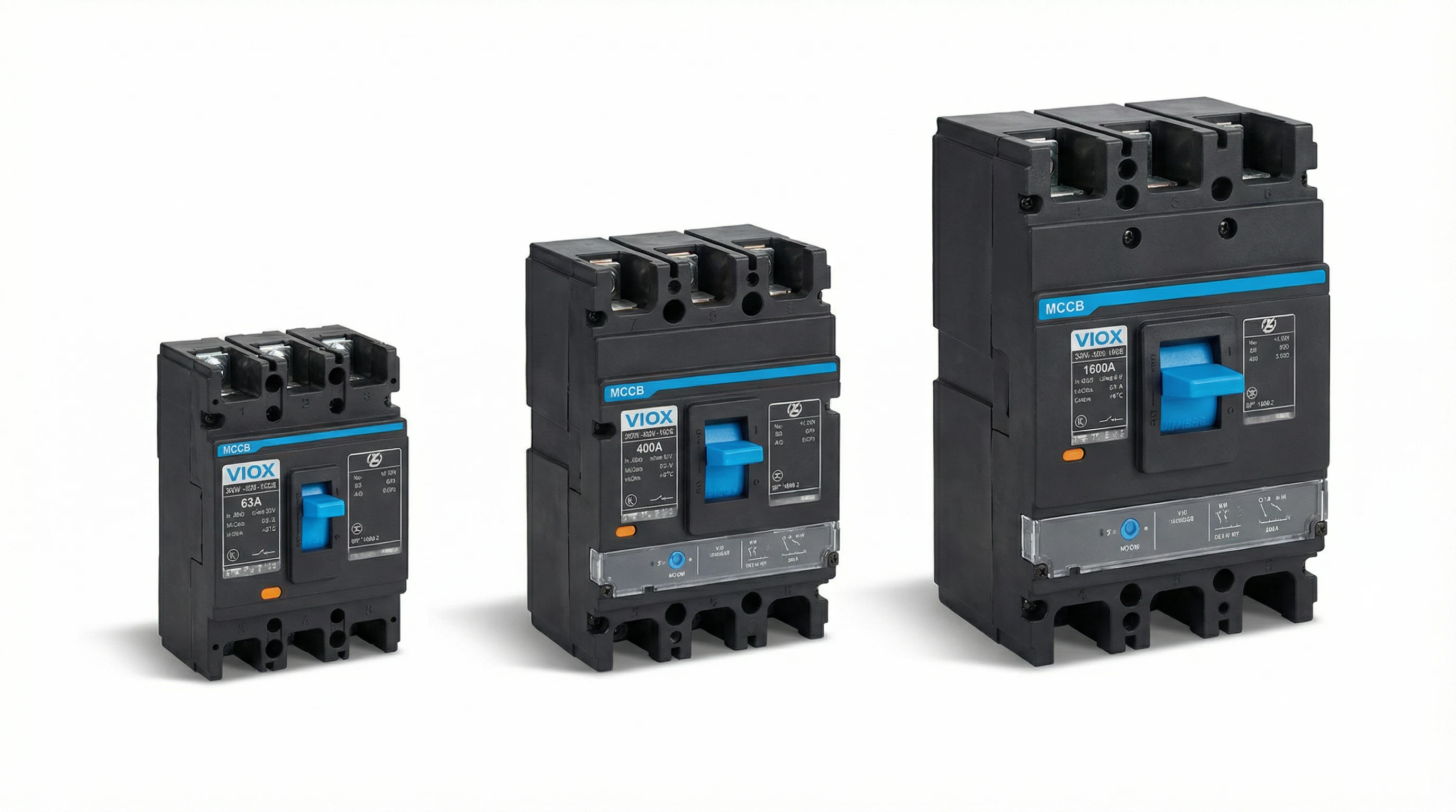
Small Frame MCCBs (16A – 250A)
Small-frame MCCBs handle the majority of branch circuit, sub-feeder, and motor protection applications in commercial and light industrial settings. They bridge the gap between MCBs (up to 125A) and larger distribution breakers.
Standard Current Ratings
| Rating (A) | Typical Applications | Common Trip Type |
| 16A | Small motor feeders, lighting panels | Thermal-Magnetic |
| 20A | Equipment circuits, small pumps | Thermal-Magnetic |
| 25A | HVAC units, small machinery | Thermal-Magnetic |
| 32A | Motor feeders (up to 15kW at 400V) | Thermal-Magnetic |
| 40A | Commercial kitchen equipment, chillers | Thermal-Magnetic |
| 50A | Medium motors (22kW), UPS feeders | Thermal-Magnetic |
| 63A | Distribution sub-feeders, large motors (30kW) | Thermal-Magnetic / Electronic |
| 80A | Building sub-distribution, motor control centers | Thermal-Magnetic / Electronic |
| 100A | Floor distribution boards, lift circuits | Thermal-Magnetic / Electronic |
| 125A | Building risers, small commercial service entrance | Electronic |
| 160A | Sub-mains, generator transfer switches | Electronic |
| 200A | Commercial sub-mains, small industrial feeders | Electronic |
| 250A | Building main feeders, industrial distribution | Electronic |
Technical Characteristics
Breaking Capacity: Small-frame MCCBs typically offer Icu ratings from 25kA to 50kA. For most commercial buildings (fault levels 20-35kA), a 36kA or 50kA frame provides adequate protection.
Trip Technology:
- 16A-63A: Usually fixed thermal-magnetic (bimetallic + electromagnetic trip)
- 63A-250A: Available in both fixed thermal-magnetic and adjustable electronic versions
- Electronic trip units offer adjustable Ir (overload) and Im (short-circuit) settings, useful for motor coordination
Poles Available: 1P, 2P, 3P, 4P configurations. Note that 1P MCCBs are less common than MCBs for single-phase circuits—most small-frame MCCBs start at 2P or 3P.
Motor Protection Example
For a 30kW / 400V three-phase motor (In ≈ 57A full-load):
- Select breaker rating: Choose 63A MCCB (next standard size above 57A)
- Verify breaking capacity: If fault level is 28kA, specify 36kA or 50kA Icu
- Trip setting: Use electronic trip with adjustable Ir set at 0.95 x In (54A thermal protection)
- Coordination: Ensure magnetic threshold Im > motor starting current (typically 6-8 x In)
When to Choose Small Frame
- Load current ≤ 250A
- Fault level ≤ 50kA
- Application involves motors, machinery, or building sub-distribution
- Space is limited (typically 70-140mm wide depending on poles)
For lower ratings (16-32A) protecting simple resistive loads, an MCB may be more cost-effective. Choose an MCCB when you need adjustable trip settings, higher breaking capacity, or better selectivity coordination.
Medium Frame MCCBs (250A – 630A)
Medium-frame MCCBs serve as the backbone of commercial and industrial distribution systems. They protect building feeders, sub-mains, and medium-voltage transformer secondaries. This range covers the majority of main distribution board applications in office buildings, shopping centers, and manufacturing facilities.
Standard Current Ratings
| Rating (A) | Typical Applications | Typical Icu Range |
| 250A | Building main feeders, industrial sub-distribution | 35kA – 65kA |
| 320A | Commercial main feeders, medium industrial loads | 35kA – 65kA |
| 400A | Building service entrance (small-medium), process equipment | 35kA – 70kA |
| 500A | Large building feeders, industrial mains | 50kA – 70kA |
| 630A | Main distribution boards, transformer secondary protection | 50kA – 85kA |
Technical Characteristics
Breaking Capacity: Medium frames offer higher Icu ratings (35-85kA) to handle the elevated fault currents typical at main distribution points. Industrial sites with on-site generation or close transformer coupling often see fault levels in the 40-65kA range.
Electronic Trip Units: Nearly all medium-frame MCCBs use electronic trip technology with:
- Ir (Overload): Adjustable from 0.4 to 1.0 x In, time-delayed thermal protection
- Isd (Short-Delay): Adjustable instantaneous short-circuit threshold, typically 1.5-10 x In
- Ii (Instantaneous): Magnetic trip for high-level faults (optional on some units)
- Ground Fault: Optional ground-fault protection module for enhanced safety
Frame Width: Expect 140-180mm width for 3-pole units, 190-240mm for 4-pole. Plan panel cutout dimensions carefully—these breakers occupy significantly more space than small frames.
Communication: Many medium-frame MCCBs offer communication modules (Modbus RTU, Profibus, Ethernet) for integration into building management systems (BMS) or SCADA.
Coordination and Selectivity
At this current level, selective coordination becomes critical. You need time-current curve analysis to ensure upstream 630A and downstream 250A breakers discriminate properly:
- Use different trip technologies: Upstream electronic (adjustable time delay) + downstream thermal-magnetic (fast)
- Verify time-current curves: Ensure at least 100-200ms discrimination time at all fault levels
- Consider S-series or ZSI: Some manufacturers offer “selective” or zone-selective interlocking for guaranteed coordination
Transformer Secondary Protection Example
For a 1000kVA / 400V transformer (In ≈ 1443A secondary):
- Calculate fault level: If transformer impedance Zk = 6%, secondary fault ≈ 24 x In = 34.6kA
- Select breaker rating: Choose 630A MCCB as main breaker (allows for future load growth to ~440kW)
- Specify breaking capacity: Icu ≥ 35kA; select 50kA or 65kA frame for margin
- Trip settings: Ir = 0.8 x 630A = 504A (allows 1443A feeder without overload trip)
- Coordination: Set Isd = 3000A with 0.2s delay for selectivity with downstream 250A breakers
When to Choose Medium Frame
- Load current 250-630A
- Fault level 30-85kA
- Application involves main distribution boards, building service entrance, or industrial feeders
- Selectivity coordination with downstream breakers is required
- Communication integration with BMS/SCADA is needed
Large Frame MCCBs (630A – 1600A)
Large-frame MCCBs protect main incomers, switchgear bus sections, and heavy industrial loads. These breakers serve as the primary protection device between the utility supply (or on-site generation) and the facility’s distribution system. At this scale, a single breaker failure can shut down an entire building or production line—reliability and coordination are non-negotiable.
Standard Current Ratings
| Rating (A) | Typical Applications | Typical Icu Range |
| 630A | Small industrial main incomer, large building service | 50kA – 100kA |
| 800A | Medium industrial main, multi-building campus distribution | 65kA – 100kA |
| 1000A | Industrial main switchboard, data center UPS incomer | 65kA – 100kA |
| 1250A | Heavy industrial mains, large commercial complexes | 85kA – 100kA |
| 1600A | Maximum MCCB rating; main switchgear, primary incomers | 85kA – 150kA |
Technical Characteristics
Breaking Capacity: Large frames offer the highest Icu ratings available in MCCB technology—65-150kA. Above this level, you typically move to Air Circuit Breakers (ACBs) with draw-out construction.
Advanced Electronic Trip Units: Large-frame MCCBs feature sophisticated microprocessor-controlled trip units with:
- Programmable time-current curves: ANSI curves, IEC curves, or custom settings
- Ground-fault protection: Adjustable sensitivity and time delay (30mA to 1200A)
- Neutral protection: 4-pole units with neutral current monitoring
- Arc-fault detection: Optional AFCI modules for fire prevention
- Metering and data logging: Real-time current, voltage, power, energy, harmonics
- Communication protocols: Modbus TCP/IP, Profinet, BACnet for integration
Physical Dimensions: A 1600A 4-pole MCCB can measure 300mm (W) x 380mm (H) x 140mm (D). Weight exceeds 15kg. Installation requires secure mounting to rated busbar or cable lugs with proper torque specifications (often 40-60 Nm terminal torque).
Testing and Maintenance: IEC 60947-2 requires large-frame MCCBs to withstand specific test sequences. After major faults (near Icu), inspect for contact erosion, arc chute condition, and mechanism wear. Many sites perform annual trip testing and 3-5 year contact resistance checks.
Switchgear Main Incomer Example
For a 2500kVA / 400V industrial facility (estimated load 3608A, demand factor 0.6 = 2165A):
- Calculate fault level: Utility fault contribution = 80kA at service point
- Select breaker rating: Choose 1600A MCCB (next standard size above 2165A demand, allows growth)
- Specify breaking capacity: Icu ≥ 80kA; select 100kA frame for safety margin
- Trip settings: Ir = 0.9 x 1600A = 1440A, Isd = 6400A / 0.4s, Ii = 15000A
- Coordination: Verify selectivity with downstream 630A feeders using time-current curves
- Communication: Connect to SCADA for load monitoring and remote trip capability
ACB vs. Large-Frame MCCB
Stick with MCCB if:
- Current ≤ 1600A
- Fault level ≤ 100kA (or 150kA with high-performance models)
- Fixed installation (no requirement for draw-out servicing)
- Budget constraints favor compact MCCB over ACB
Switch to ACB if:
- Current > 1600A (ACBs extend to 6300A+)
- Draw-out construction needed for maintenance without downtime
- Extremely high fault levels (>100kA) require ACB interrupting technology
- Application demands visible contact separation or extensive auxiliary contacts
When to Choose Large Frame
- Load current 630-1600A
- Fault level 50-150kA
- Application involves main incomers, switchgear, or critical distribution points
- Advanced protection (metering, communication, ground-fault) is required
- Budget and space favor MCCB over ACB technology
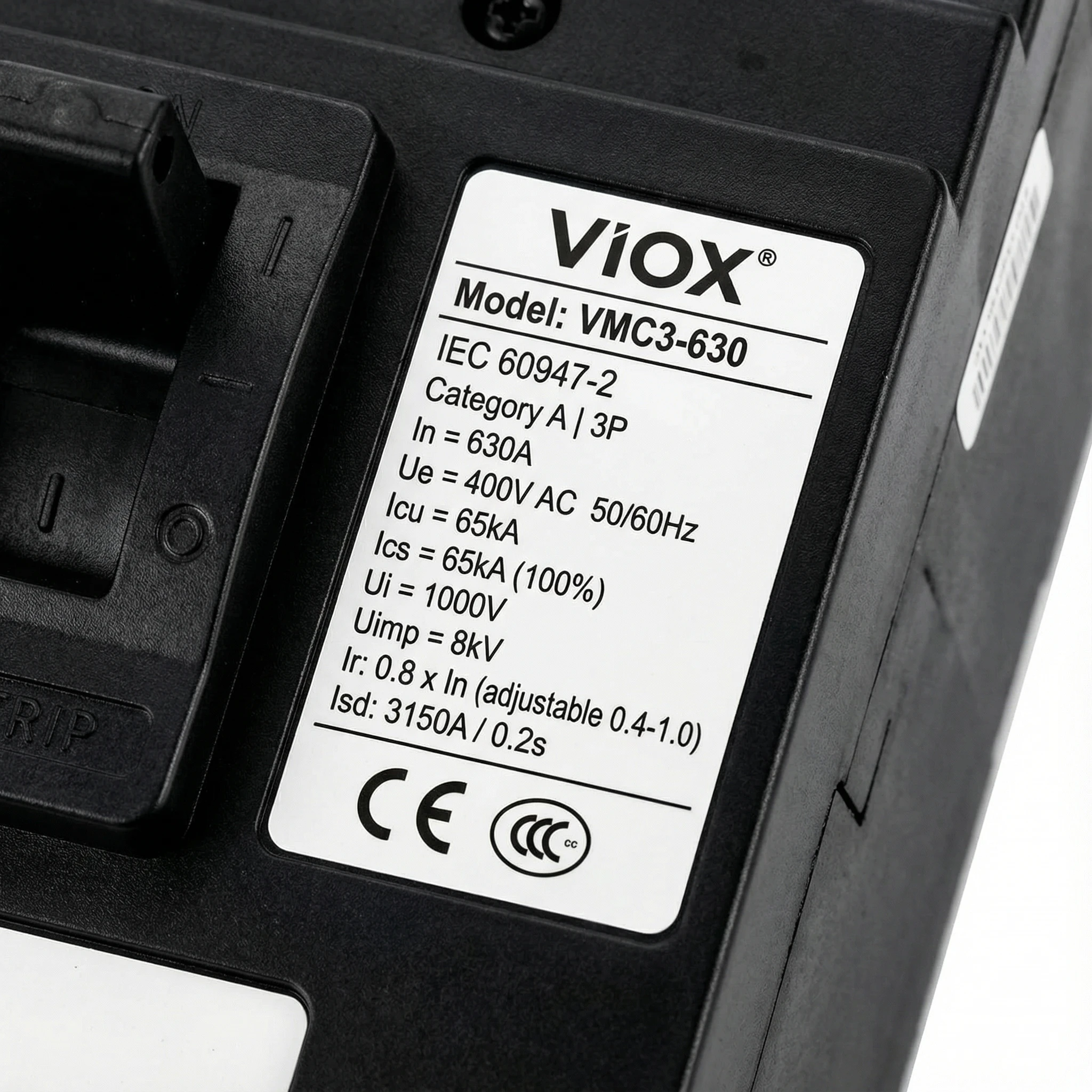
How to Read MCCB Rating Plates
Every IEC-compliant MCCB carries a rating plate (nameplate) that displays critical specification data. Understanding how to decode this information ensures you select, install, and maintain breakers correctly.
Essential Nameplate Information
A typical MCCB rating plate includes:
- 1. Manufacturer and Model: Brand name and product series (e.g., “VIOX VMC3-630”)
- 2. IEC Standard Marking: “IEC 60947-2” or “EN 60947-2” confirms compliance
- 3. Rated Current (In): The breaker’s nominal current rating at reference ambient (40°C)
- 4. Rated Voltage (Ue): Operational voltage rating (e.g., 690V AC, 250V DC)
- 5. Breaking Capacity (Icu / Ics): Icu (Ultimate) and Ics (Service) limits in kA
- 6. Utilization Category: Category A (instantaneous) or Category B (time-delayed)
- 7. Rated Insulation Voltage (Ui): Maximum system voltage withstand
- 8. Rated Impulse Withstand Voltage (Uimp): Surge immunity (e.g., 8kV)
- 9. Poles and Configuration: 3P or 4P
- 10. Trip Settings: Ranges for Ir, Isd, Ii (if adjustable)
- 11. Certifications: CE, CCC, UL marks
What to Verify Before Installation
- In ≥ calculated load current (with derating for temperature/grouping if applicable)
- Ue = system voltage (must match; 400V breaker cannot protect 690V system)
- Icu ≥ prospective fault current at installation point
- Ics appropriate for application (75-100% for most critical applications)
- Poles match system: 3P for three-phase, 4P if neutral protection required
- Trip settings (if adjustable) configured per coordination study
- Certifications valid for installation region
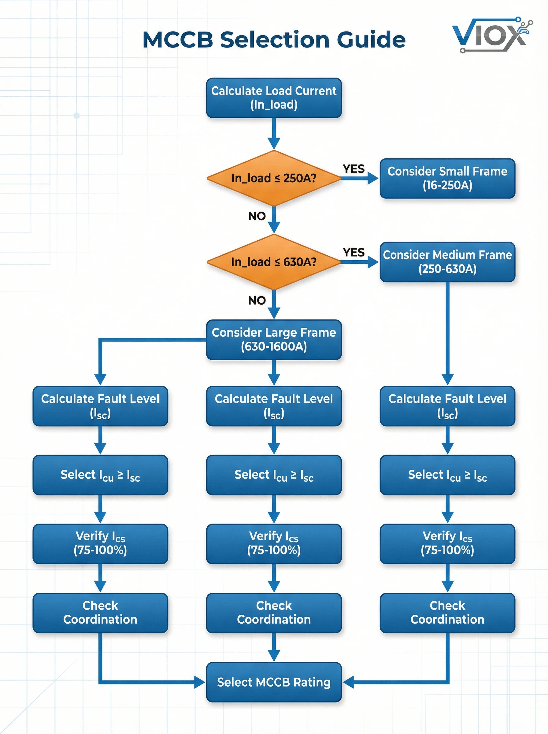
Selection Guide by Application
Choosing the right MCCB current rating depends on your specific application, load type, fault level, and coordination requirements.
Quick Selection Table
| Application | Load Current | Recommended MCCB Rating | Typical Icu |
| Small motor (7.5kW) | 15A | 20A or 25A | 25-36kA |
| Medium motor (30kW) | 57A | 63A or 80A | 36-50kA |
| Large motor (110kW) | 200A | 250A | 50-65kA |
| Office floor feeder | 180A | 200A or 250A | 36-50kA |
| Building sub-main | 450A | 500A or 630A | 50-65kA |
| Small service entrance | 650A | 800A | 65-85kA |
| Industrial main | 1200A | 1250A or 1600A | 85-100kA |
Critical Selection Reminders
- Never undersize In: A breaker carrying 90% of its rating continuously will overheat and degrade
- Always verify Icu: Undersized breaking capacity can cause catastrophic breaker failure during faults
- Check ambient temperature: Standard ratings assume 40°C; derate for higher temperatures (0.9x at 50°C, 0.8x at 60°C)
- Coordinate time-current curves: Use manufacturer software to verify selectivity across the entire distribution system
- Consider future growth: Specify 10-25% margin in In for facility expansion
Conclusion
Standard MCCB current ratings from 16A to 1600A form the foundation of modern electrical distribution systems. Understanding the relationship between frame sizes, current ratings, and breaking capacities allows you to specify breakers that protect equipment, ensure system coordination, and meet IEC 60947-2 safety standards.
Key takeaways:
- Match In to load requirements with 10-25% margin for growth and derating
- Verify Icu against fault studies—never install a breaker with insufficient breaking capacity
- Choose frame size wisely—small frames for ≤50kA / ≤250A, medium for 30-85kA / 250-630A, large for 50-150kA / 630-1600A
- Read rating plates carefully—confirm In, Ue, Icu, Ics, poles, and certifications before installation
- Coordinate with system studies—use time-current curves to ensure selectivity across distribution hierarchy
Whether you’re protecting a 30kW motor with a 63A breaker or specifying a 1600A main incomer for an industrial facility, the principles remain the same: accurate load calculation, proper breaking capacity, and verified coordination.
Need assistance selecting the right MCCB for your project? VIOX Electric manufactures IEC 60947-2 compliant MCCBs across all standard ratings from 16A to 1600A. Our engineering team provides technical support for breaker selection, coordination studies, and system design. Contact us for specifications and technical consultation.
