
According to the Electrical Safety Foundation International (ESFI), electrical malfunctions cause approximately 51,000 structure fires annually in the U.S. alone, resulting in over $1.3 billion in property damage. At the heart of every electrical system’s defense strategy is the circuit breaker—a device designed to interrupt current flow during faults. However, when a circuit breaker fails to operate correctly, it transforms from a safety device into a silent hazard.
Identifying a bad circuit breaker before catastrophic failure occurs is a critical skill for facility managers and electrical professionals. Unlike a blown fuse which clearly indicates interruption, a malfunctioning breaker may appear normal while secretly allowing dangerous overcurrents to persist. This guide details the engineering principles behind breaker failure, systematic testing protocols, and the professional diagnostics required to ensure your electrical infrastructure remains secure.
⚡ Key Signs Your Circuit Breaker Is Going Bad
- Physical Heat: The breaker is hot to the touch (not just warm).
- Smell: A fishy or burning plastic odor near the panel.
- Visuals: Scorch marks, melted plastic, or frayed wires.
- Performance: It trips immediately after resetting (even with no load), or will not stay in the ON position.
- Sound: Buzzing or hissing noises coming from the box.
Need a reliable replacement? Check out VIOX’s Industrial Circuit Breaker Catalog.
Understanding Circuit Breaker Failure Modes
While a standard circuit breaker is engineered for longevity—typically lasting 30 to 40 years—its internal components are subject to mechanical wear, contact erosion, and environmental degradation. Understanding the specific failure modes of different breaker types is essential for accurate diagnosis.
Environmental factors significantly accelerate aging. High humidity can lower insulation resistance, while frequent tripping under load causes arc pitting on contacts. Furthermore, modern loads with high harmonic content can cause thermal stress on bimetallic strips within thermal-magnetic breakers.
For a deeper understanding of breaker classifications, refer to our guide on What Is the Difference Between MCB, MCCB, RCB, RCD, RCCB, and RCBO?, or explore heavy-duty options in our MCCB vs ICCB Comprehensive Guide.
Common Failure Modes by Breaker Type
| Breaker Type | Primary Mechanism | Common Failure Mode | Root Cause |
|---|---|---|---|
| MCB (Miniature Circuit Breaker) | Thermal-Magnetic | Failure to Trip or Nuisance Tripping | Weakened bimetallic strip or stuck spring mechanism. |
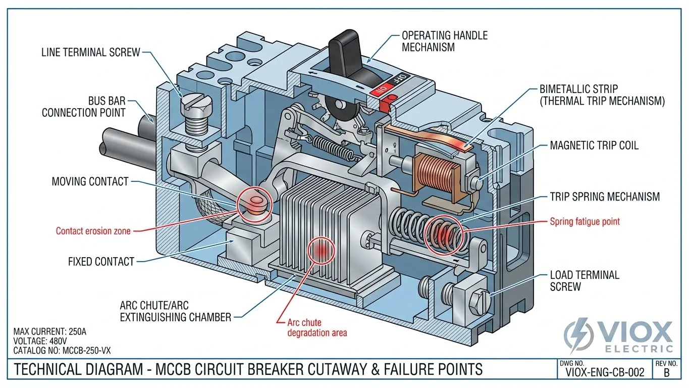
| MCCB (Molded Case Circuit Breaker) | Electronic/Thermal-Magnetic | Contact Welding | High fault current clearing without replacement; contacts fuse together. |
| RCCB/RCD (Residual Current Device) | Core Balance Transformer | Test Button Failure | Internal resistor burnout or sensing coil deterioration. |
| RCBO (Residual Current Breaker with Overcurrent) | Combined | Electronic Component Failure | Surge damage to the PCB controlling earth leakage detection. |
Visual and Physical Warning Signs
Before employing diagnostic tools, a thorough sensory inspection often reveals the status of a bad circuit breaker. The physical condition of the breaker and the distribution panel provides immediate data points regarding thermal stress and mechanical integrity.
For specific signs related to larger air systems, see our article on 7 Critical Warning Signs Your Air Circuit Breaker Is Failing.
Key Indicators of Failure
- Burning Smell and Overheating: A distinct acrid odor (often smelling like burning fish or plastic) indicates insulation breakdown. If a breaker is hot to the touch—not just warm—it suggests internal resistance is generating dangerous heat levels, potentially due to loose terminal connections or contact degradation.
- Visible Damage: Look for scorch marks on the terminal screws, melted casing around the handle, or corrosion on the busbar connection. These are signs that How MCBs Prevent Damage During Electrical Overloads or Short Circuits has been compromised.
- Refusal to Reset: If a breaker trips, the handle often moves to a middle position. Pro Tip: Many users mistakenly believe a breaker is broken because it won’t push back to ON immediately. You must firmly push the handle to the OFF position until you hear a distinct “click” to reset the internal spring mechanism before pushing it back to ON. If the handle still feels “mushy” or won’t latch after this procedure, the internal mechanical latch has failed.
- Audible Noise: A healthy breaker is silent. Buzzing, crackling, or sizzling sounds indicate arcing—electricity jumping across a gap due to loose connections or internal component failure.
Troubleshooting: Circuit Overload vs. Bad Breaker
Before assuming the breaker itself is defective, it is crucial to rule out external causes. A breaker’s primary job is to trip during overloads; if it does so, it is functioning correctly, and the issue lies with the circuit load.
“Ghost Tripping” refers to breakers that trip for no apparent reason. This often stems from a degraded trip curve where the breaker becomes hypersensitive, tripping well below its rated limit.
Step-by-Step Isolation Test
- Disconnect Everything: Unplug every appliance and turn off every light switch on the affected circuit.
- Reset the Breaker: Push the handle firmly to OFF, then to ON.
- Observation:
- Scenario A (Immediate Trip): If it trips instantly with nothing connected, the breaker is likely faulty (internal short) or there is a dead short in the wall wiring.
- Scenario B (Holds Power): If it stays ON, the breaker is likely mechanically sound.
- Reintroduce Load: Plug devices back in one by one. If it trips only when a specific high-wattage appliance (like a space heater) is turned on, the circuit is overloaded, not broken.
Quick Diagnostic Decision Tree
- Does the breaker reset?
- No (Trips instantly with no load) → Check for short circuit in wiring. If wiring is clear → Replace Breaker.
- Yes (Stays ON) → Proceed to Load Test.
- Does it trip later?
- Yes → Check Amp Draw with Clamp Meter.
- High Amps (>80% of rating) → Circuit Overloaded → Reduce Load.
- Normal Amps (<80% of rating) → Breaker Trip Curve Degraded → Replace Breaker.
- Yes → Check Amp Draw with Clamp Meter.
Symptom Analysis: Overload vs. Breaker Failure
| Symptom | Circuit Overload (Normal Operation) | Bad Circuit Breaker (Failure) |
|---|---|---|
| Timing | Trips after a few minutes/hours of use | Trips instantly or randomly (Ghost Trip) |
| Resetting | Resets after cooling down | Handle feels loose/mushy; won’t latch |
| Physical Signs | Panel cover is warm | Burning smell; Breaker is hot to touch |
| Cause | Too many amps for rating | Weak internal springs/contacts |
DIY Testing Methods: Multimeter and Mechanical Checks
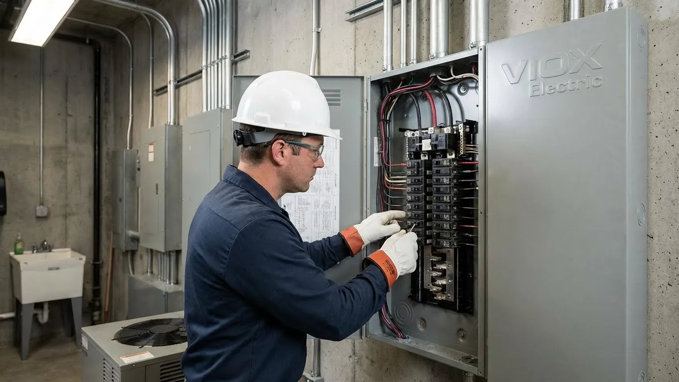
For facility technicians and qualified personnel, verifying a bad circuit breaker involves testing its electrical continuity and voltage output. Safety Warning: Working inside an electrical panel carries the risk of arc flash and electrocution. Always wear appropriate PPE (Personal Protective Equipment) and adhere to NFPA 70E guidelines.
3.1 Visual Inspection Steps
Begin by removing the panel cover (dead front). Inspect the breaker in question for physical alignment. A breaker that is loose on the DIN rail or busbar allows for micro-arcing, which creates heat and destroys the connection point.
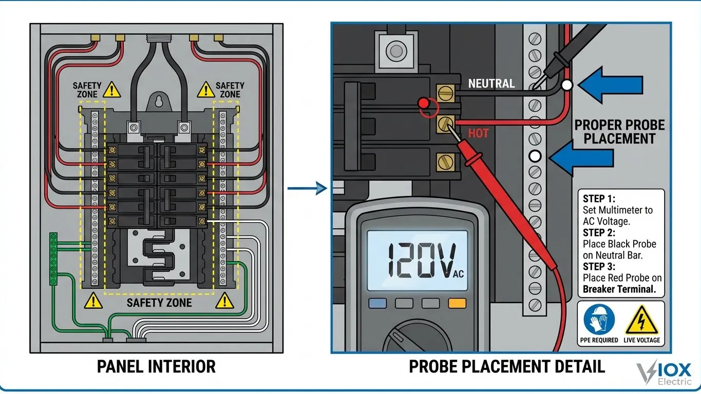
3.2 Multimeter Voltage Testing
This is the definitive test for a breaker under load.
- Setup: Set your digital multimeter to Volts AC (typically the 600V or 750V setting).
- Ground Reference: Place the Black (Common) probe on the neutral bus bar (usually a silver strip with white wires) or the ground bar (green wires/bare copper).
- Live Measurement: With the breaker in the ON position, carefully touch the Red probe to the terminal screw of the breaker.
- Interpretation:
- 120V / 240V (Single/Double Pole): The breaker is passing voltage correctly. If the circuit is still dead, the issue is likely in the wiring downstream.
- 0V or Fluctuating Low Voltage: The breaker is faulty. The internal contacts are not closing, or the bus connection is severed.
3.3 Continuity Testing (Power Off)
This method is safer as it is performed on a de-energized breaker. For a detailed guide, read How to Test a Circuit Breaker Without Power.
- Isolate: Turn off the Main Breaker. Disconnect the wire from the breaker terminal to isolate it from the circuit load.
- Setup: Set multimeter to Continuity (audible beep mode) or Ohms (Ω).
- Test ON State: Flip the breaker ON. Touch one probe to the bus clip (back of breaker) and the other to the screw terminal.
- Result: Multimeter should beep or read near 0 Ω.
- Test OFF State: Flip the breaker OFF. Repeat the probe contact.
- Result: Multimeter should be silent or read “OL” (Open Line/Infinite Resistance).
- Failure: If it beeps while OFF, the contacts are welded shut—a dangerous condition.
3.4 Mechanical Operation Testing
Toggle the handle ON and OFF multiple times. It should snap decisively. If the handle stops in the middle (trip position) without being forced, or slides without resistance, the spring mechanism is broken. For RCDs/GFCIs, press the “TEST” button. If the breaker does not trip instantly, the sensing coil or electronic trigger is dead.
Testing Method Comparison
| Method | Tools Required | Safety Level | Accuracy | When to Use |
|---|---|---|---|---|
| Voltage Test | Multimeter (CAT III/IV) | Low (Live Work) | High | To confirm power output under load. |
| Continuity | Multimeter | High (Power Off) | Medium | Safest method; checks internal contact state. |
| Mechanical | Hand / Screwdriver | High | Low | Initial check for jammed mechanisms. |
| Load Test | Clamp Meter | Medium | High | Verifying if tripping is caused by true overload vs. breaker fault. |
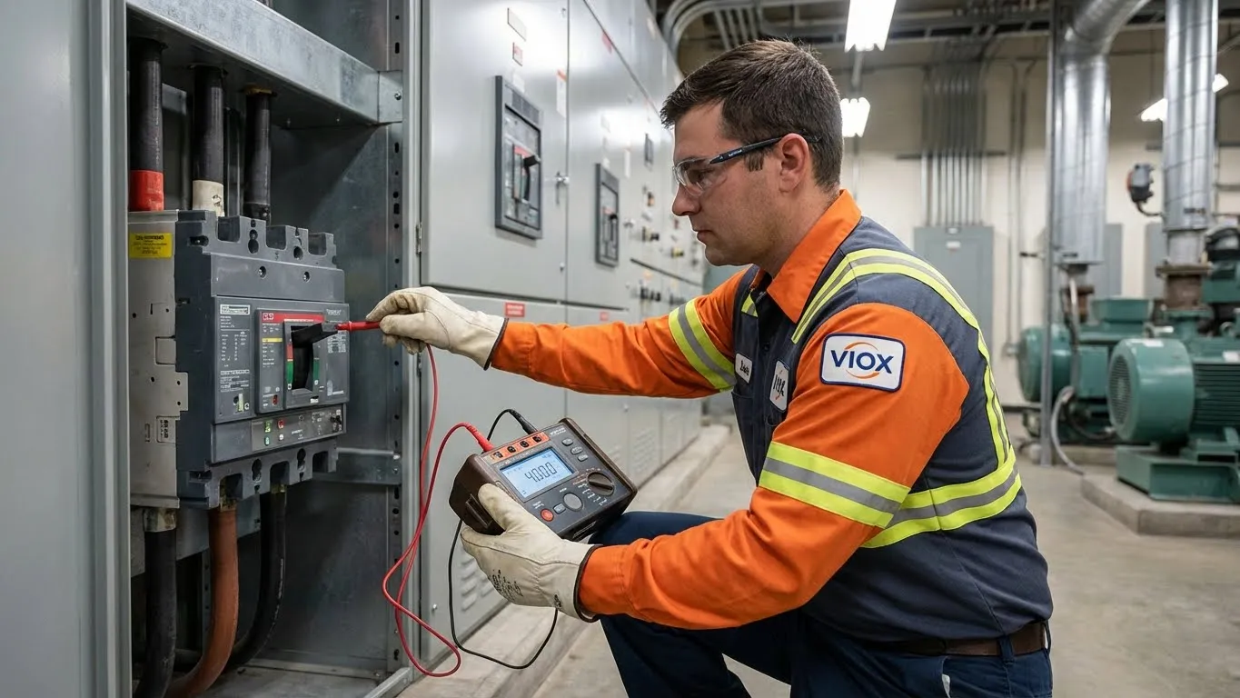
Professional Diagnostic Methods
For industrial environments or critical infrastructure utilizing sophisticated protection like those described in our Current Limiting Circuit Breaker Guide, simple multimeter tests are insufficient. Professional testing analyzes the insulation integrity and trip curve characteristics.
Insulation Resistance Testing (Megger)
This test uses a megohmmeter to apply 500-1000 Vdc to the breaker contacts. It measures leakage current through the insulation.
- Procedure: Measure Phase-to-Ground, Phase-to-Phase, and Line-to-Load (breaker Open).
- Benchmark: Readings should typically exceed 1 Megohm for used breakers (higher for new ones). A drop in resistance indicates moisture ingress or carbon tracking.
Thermal Imaging (Thermography)
Thermography is a standard preventive maintenance tool in industrial settings. Technicians use infrared cameras to scan the breaker panel under load.
- Hot Spots: High-resistance connections appear as bright hot spots on the thermal image.
- Thresholds: A temperature difference (ΔT) of >15°C to 20°C above ambient or compared to adjacent phases indicates a critical connection failure or internal contact degradation requiring immediate replacement.
Timing Measurement Tests
Using a circuit breaker analyzer, engineers measure the Opening Time (trip initiation to contact separation) and Clearing Time (arc extinction). Slow operation indicates hardened grease or worn mechanical linkages, which compromises the Circuit Breaker Ratings: ICU, ICS, ICW, ICM.
Static Resistance Measurement (Ducter Test)
This involves injecting high current (100-200A DC) through the closed contacts and measuring the voltage drop (micro-ohm resistance).
- Purpose: Detects contact erosion or loose internal connections that standard multimeters cannot see due to low test current.
Load Testing with a Clamp Meter
This is the only definitive way to distinguish a “weak” breaker from a true overload without taking the breaker offline.
- Procedure: Clamp the meter around the load wire (live wire) exiting the breaker.
- Analysis: Measure the current draw while the circuit is active. If a 20A breaker trips while the meter reads only 10A, the breaker’s thermal element has weakened (degraded trip curve) and must be replaced.
Professional Diagnostic Table
| Test Type | Equipment Used | What It Measures | Acceptable Range | Frequency |
|---|---|---|---|---|
| Insulation Resistance | Megohmmeter | Dielectric strength of insulation | > 50 MΩ (Low Voltage) | Every 3-5 Years |
| Contact Resistance | Micro-ohmmeter | Resistance of main contacts | < 100-200 μΩ (varies by rating) | Every 1-3 Years |
| Primary Injection | Current Injector | Thermal/Magnetic trip characteristics | Within trip curve tolerance | Commissioning / Post-repair |
| Timing Test | Analyzer | Mechanism speed | Milliseconds (ms) per spec | Critical Maintenance |
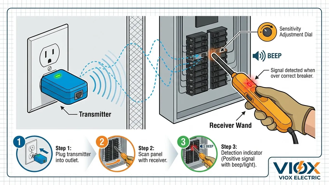
Circuit Breaker Identification Tools
Before testing can begin, correctly identifying the specific circuit breaker feeding a faulty outlet is mandatory. In commercial settings with unorganized labeling, this is a challenge.
Circuit Breaker Finders utilize a transmitter plugged into the outlet and a receiver wand scanned over the panel. As the receiver passes the correct breaker, it detects the signal injected by the transmitter. Professional models, such as the Extech CB10 or equivalent industrial tracers, allow for sensitivity adjustment to eliminate “ghost” signals from adjacent breakers. Using these tools prevents the dangerous error of turning off the wrong breaker before commencing work.
When to Call Professional Electricians
While DIY testing is valuable for initial troubleshooting, electrical systems possess lethal potential. You must contact a licensed professional immediately if you observe emergency warning signs:
- Visible Arcing or Sparks: Indicates a major containment failure.
- Hot Panel Front: If the metal cover of your panel is hot, the busbars may be overheating.
- Frayed Main Feeder Wires: Do not attempt to touch or repair service entrance cables.
CRITICAL WARNING: If your electrical panel is Federal Pacific Electric (FPE), Zinsco, or Challenger brand manufactured before 1990, do not attempt testing. These panels have documented failure rates exceeding 25% and should be replaced immediately by a licensed electrician. The testing procedures in this article do not apply to these hazardous legacy systems.
When replacing a breaker, ensuring compatibility with your panel manufacturer and bus bar system is crucial. VIOX breakers are designed with strict compliance to IEC 60947 and UL 489 standards, making them a reliable upgrade for aging infrastructure across industrial and commercial applications.
Furthermore, if your breakers are over 40 years old, professional replacement is non-negotiable. Ensuring compliance with local codes is vital for insurance and safety. For those looking to source reliable replacements, VIOX is a leader in global standards; you can review our standing among the Top 10 Circuit Breaker Manufacturers in China.
FAQ
Q: How long do circuit breakers typically last?
A: Standard molded case circuit breakers (MCCBs) and MCBs typically last between 30 to 40 years under normal operating conditions, though high humidity or frequent tripping can shorten this lifespan significantly.
Q: Can a circuit breaker fail without tripping?
A: Yes. This is known as a “fail-closed” condition. The internal mechanism may jam, or contacts may weld together, preventing the breaker from opening even during an overload. This is the most dangerous type of failure.
Q: What voltage reading indicates a bad breaker?
A: If the breaker is switched ON and you measure 0V (or significantly less than the rated voltage, e.g., 60V on a 120V circuit) between the terminal and neutral bus, the breaker is likely bad.
Q: What is the difference between AC and DC breaker failure?
A: DC arcs are harder to extinguish than AC arcs because there is no zero-crossing point. A DC breaker often fails due to arc chute degradation. For more details, read What is a DC Circuit Breaker.
Q: Is it safe to test a circuit breaker myself?
A: Basic visual checks and continuity tests (on a dead breaker) are safe for competent individuals. However, voltage testing on a live panel requires appropriate PPE and training. If unsure, always hire a professional.
Q: What’s the difference between MCB and MCCB failure modes?
A: MCBs tend to fail mechanically (springs/latch), while MCCBs, which handle higher currents, are more prone to contact erosion and electronic trip unit failures.
